
Automated Draping of Wide Textiles on Double Curved Surfaces
Patrick Kaufmann
a
, Georg Braun
b
, Andreas Buchheim
c
and Marcin Malecha
d
German Aerospace Center, Institute of Structures and Design, Center for Lightweight Production Technology (ZLP),
86159 Augsburg, Germany
Keywords: Automation, Layup, Draping, Textile, Double Curved Surface, Automated Preforming.
Abstract: In many different industries like aviation, shipbuilding or the production of wind turbines, the draping of
textiles is a common issue. Especially large components in long- and medium-haul aircraft have a high po-
tential of weight reduction by using composites. In many cases increasing material and manufacturing costs
are caused compared to metal design. Therefore automation is one approach to achieve profitability. A robot
end effector for the automated deposition of 50 inch wide fibre fabrics was tested. The experiments were
performed in full scale, with plies of an aircraft pressure bulkhead. When depositing these fabrics on curved
surfaces, defects such as waves or wrinkles appear. In order to solve this issue, the end effector was extended
by adding an adaptable material buffer. The development regarding mechanical design, calculation for deter-
mining the axis movement as well as the axes control is presented. Compared to previous attempts without an
adaptable material buffer, an improved deposition quality was achieved. The results of the experimental in-
vestigation are shown.
1 INTRODUCTION
In the field of aviation, wind turbines and ships, large
components made of fibre composites are used, as
these have a very good strength to weight ratio. Dur-
ing the production of these components in the process
step referred to as preforming large textiles have to be
deposited on shape-giving moulds. This can be done
via precut plies or by direct deposition from the sup-
ply roll in a rolling motion. In order to reduce produc-
tion costs, a high deposition rate (kg/h) is targeted. In
this context, the influencing factors for a specific au-
tomated process are the process speed and the type of
fabric used. One approach to increase the deposition
rate is the use of wide textiles with a material width
of up to approximately 1270 mm (50 inch).
During preforming, the textiles have to be manip-
ulated to conform to the mould surface. In case of
double curved geometries draping is necessary.
(Elkington et al., 2017) In this process the textile is
distorted in a defined way, meaning that the angle be-
tween weft and warp roving (shear angle) is modified
a
https://orcid.org/0000-0003-1181-7211
b
https://orcid.org/0000-0002-8181-5513
c
https://orcid.org/0000-0003-3333-7227
d
https://orcid.org/0000-0003-2824-0914
locally. The maximum achievable change of the shear
angle (locking angle) depends on the geometry of the
mould and the type of textile. (Manson et al., 2000)
The use of wide textiles in terms of preforming poses
special challenges, as larger areas have to be manipu-
lated at the same time. If draping is insufficient, fabric
imperfections will appear. Thus, out-of-plane defor-
mation in form of wrinkles can occur at the inner ra-
dius of curved plies (Olsen and Craig, 1993). Since
the components mechanical properties depend to a
large extent on the quality of the preforming,
measures must be taken to prevent fabric imperfec-
tions. Therefore the main challenge is the develop-
ment of a process that allows the draping of textiles
to be controlled in a defined way. In this respect, the
main influencing factors in the automated rolling dep-
osition of textiles must be considered, such as syn-
chronization of the rotary movement of the supply
roll and end effector movement, contact pressure on
the mould surface and length differences between in-
ner and outer radius of curved plies. The compensa-
tion of these length differences was investigated in
the present work by developing an adaptable material
50
Kaufmann, P., Braun, G., Buchheim, A. and Malecha, M.
Automated Draping of Wide Textiles on Double Curved Surfaces.
DOI: 10.5220/0007833200500058
In Proceedings of the 16th International Conference on Informatics in Control, Automation and Robotics (ICINCO 2019), pages 50-58
ISBN: 978-989-758-380-3
Copyright
c
2019 by SCITEPRESS – Science and Technology Publications, Lda. All rights reserved

buffer for a robot end effector used for the rolling dep-
osition of carbon fibre fabrics.
2 STATE OF THE ART
In the manufacturing process of fibre composite
structures, the layup and draping of textiles is often
still carried out manually, such as for the rear pressure
bulkhead of particular aircraft types (Schnitzer,
2013), wind turbine blades (Zhu, 2015) or shipbuild-
ing. For this purpose, precut textiles are used. The fi-
nal draping is done by manually applying pressure on
the fabric. The worker's level of skill and experience
is decisive here in order to avoid inducing fabric im-
perfections and achieve the desired positioning toler-
ance.
The most well-established automated processes in
the industrial production of composite components
are the rolling deposition of textiles with Automated
Tape Laying (ATL) and Automated Fibre Placement
(AFP). These processes can be carried out completely
automated with systems from various manufacturers,
such as Fives (France) or MTorres (Spain). (Sloan,
2008, Marsh, 2011) Here a respective placement head
end effector is guided by an industrial robot or a gan-
try system. In most cases an active system to prevent
wrinkles during depositing is not integrated. These
are avoided by adhering to the process constraints en-
suring that the process-specific minimum depositing
radii are not exceeded.
The ATL process consists of applying one or more
tapes from supply rolls to the mould surface simulta-
neously. The tapes have a width of approximately 75
- 300 mm (3 - 12 inch). A maximum material width
of approximately 600 mm (24 inch) can be achieved
in a multitape configuration. Since steering is only
possible to a limited extent due to the material width,
the process is mainly used for large flat or simply
curved components, such as wing skins, fuselage pan-
els (Gardiner, 2011) or wind turbine blades (Black,
2009).
One approach for applying tapes to more complex
geometries is the advanced ply placement process
(APP). (Szcesny et al., 2017) Here, precut plies are
gripped and guided by two robots to the correct posi-
tion. Simultaneously, a third robot drapes the textiles
onto the mould surface with a roll end effector.
The AFP process is comparable to ATL. Here, up
to 32 narrow textile strips (tows) with a width be-
tween 3.175 and 12.7 mm (1/8 - 1/2 inch) are deposi-
tioned at once. An overview of the process can be
found in (Kozaczuk, 2016). Compared to ATL,
smaller steering radii can be achieved due to the use
of smaller textiles. Depending on the degree of cur-
vature, gaps or overlaps between the tows can occur,
which can only be tolerated to a certain degree, since
they have a negative influence on the mechanical per-
formance (Croft et al., 2011). A summary of the ca-
pabilities and limitations of the ATL and AFP process
is given in (Lukaszewicz et al., 2012).
Another approach of depositing textiles on double
curved surfaces shows (Zhu et al., 2017). The auto-
mated layup of 280 mm wide dry glass-fibre non-
crimp fabric (NCF) was tested with a method called
shifting. Hereby the fabric is manipulated in such way
that no out-of-plane waviness occurs.
Few publications regarding rolling deposition of
textiles with widths over 600 mm can be found. As
part of the research project "mapretec" (Ohlendorf et
al., 2014) an end effector was developed which can
be used to wind up precutted plies with a maximum
width of approximately up to 1270 mm (50 inches)
and apply them to the layup position by rolling. How-
ever, only deposition on flat surfaces without contact
to the mould surface is possible, since the rigid struc-
ture of the end effector does not allow adaptation to
the mould geometry. Draping is carried out separately
by means of a form variable tooling. Likewise, end
effectors with comparable properties were developed
in the research projects "preblade" (Weigel and
Müller, 2007) (material width: 300 - 1300 mm, max.
ply length: 10 m) and "PRO-CFK" (Müller, 2007)
(max. material width: 1400 mm). In the latter, the di-
rect deposition of the textiles from the supply roll into
the contoured mould was additionally tested. Here no
precutted textiles are used. The ply length is only lim-
ited by the material quantity on the supply roll. The
draping takes place without active control via the de-
positing movement of the textile.
The layup process of the Precision Feed End Ef-
fector (PFE) developed by Automated Dynamics
(Groppe, 2007, Black, 2003) is comparable to the pro-
cess of the end effector used in this study. The PFE
features a flexible compaction roller design and can
accommodate curved panels with a 40-ft minimum
radius. It is possible to process textiles with an ap-
proximately width of 150 - 1500 mm (6 - 60 inch).
The end effector developed in the context of the re-
search project "BladeMaker" (Richrath et al., 2017) is
also capable for layup on double curved moulds. The
precut plies can have a material width of up to 1270
mm (50 inch).
A general overview of existing roller gripping and
draping systems is given in (Ehinger, 2013).
Automated Draping of Wide Textiles on Double Curved Surfaces
51
3 RESEARCH ISSUE
One big issue according the automated handling of
textiles is: how to apply a two-dimensional fabric
onto a three-dimensional mould without creating
waves, wrinkles or other critical defects. In this con-
text waves are out of plane defects characterized
through their width and height while wrinkles are de-
fects in which the fabric doubles over itself (Wade,
2012). The compensation of different lengths be-
tween the two textile edges is one approach to an au-
tomated draping of textiles.
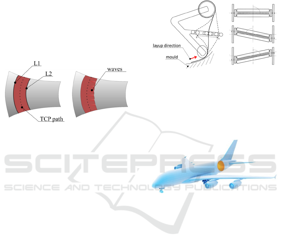
Figure 1: Generic sketch of a textile ply on an aircraft fuse-
lage with the path of Tool Centre Point (TCP).
Looking at the geometry of a generic aircraft fu-
selage and the ply placed on it, one can see that L2 in
Figure 1 is shorter than L1. Depositing the ply with-
out further measure would cause waves due to the sur-
plus material on L2. A compensation of the difference
in lengths of L1 and L2 is necessary.
Dependent on the process conditions one solution
could be to perform an optimized path generation to
overcome this issue (Schmidt-Eisenlohr et al., 2019).
In the considered scenario, the fibre angles are critical
to the mechanical properties of the component.
Therefore it is not possible to modify the ply orienta-
tion. A different approach for a defect free draping
process had to be found.
4 APPROACH
One approach to buffer the different length of the ply
in the robot end effector is a mechanical solution.
Therefore an adaptable material buffer was devel-
oped.
The concept was to create a mechanical buffer that
could independently add or absorb material from both
sides of the fabric as needed. Assuming that the cur-
vatures on large aircraft components are not subject
to strong fluctuations, a system was conceived that
contains an additional deflection roller between two
independently movable and electrically driven linear
guides. With this setup it should be possible to influ-
ence the lengths of the two edges of the fabric without
affecting the layup position. Figure 2 shows a sketch
of this concept.
Figure 2: Material buffer concept.
4.1 Process Description
The use case considered in the work for draping tex-
tiles is the automated preforming of a rear pressure
bulkhead of an airplane. This component is located at
the end of the aircraft cabin. It is highlighted in Figure
3.
Figure 3: Rear pressure bulkhead in an aircraft.
In Figure 4 the used end effector guided by an in-
dustrial robot together with the mould and one ply is
shown. There are three curves highlighted: L1 as the
length of the left edge and L2 as the length of the right
edge of the ply and the path of the Tool Centre Point
(TCP). The TCP is located in the middle of the drap-
ing roll (see Figure 5 and Figure 6) and has contact to
the mould during the deposition process. The draping
roll can be adapted by five linear units to ensure a
compliant contact over the whole width of the draping
roll. Further it is driven by five stepper motors at the
bearing points of the linear units. The stepper motors
are synchronised to the robot movement.
The deposition process starts with a robot move-
ment into the start positon. Then the contour of the
draping unit is adapted to the mould surface by mov-
ing the linear units. After that the robot moves per-
pendicularly into the mould and presses the draping
roller onto the surface. The torque control of the lin-
ear units is switched on and the deposition process
starts.
ICINCO 2019 - 16th International Conference on Informatics in Control, Automation and Robotics
52
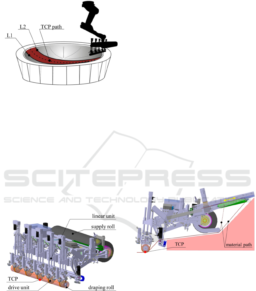
Figure 4: Experimental setup.
The trajectories for the depostion process have to
be perpendicular to the mould surface. Thus the paths
generation is quite complex and would be to impre-
cise and time consuming by hand. Therefore the robot
movement is generated by Offline Programming
(OLP). The OLP is based on a CAD model of the ro-
botic cell, the mould and the end effector. It can gen-
erate the programs for the robot motion.
4.2 Mechanical Design
As mentioned, the motivation for adding a material
buffer was the occurrence of waves during previous
layup test. The end effector used was designed by
Premium Aerotec as part of the project AZIMUT
(Niefenecker, 2014) and is shown in Figure 5
Figure 5: End effector without material buffer.
With the scope of the design of the material buffer
various requirements had to be observed. The main
technical requirements are:
The added weight to the end effector must not lead
to an overload of the robot.
The maximum moment of inertia of the entire end
effector, including the buffer, is decisive for the
movement processes of the robot. It has to be
taken into account when designing the storage ca-
pacity.
The end effector together with the material buffer
must not collide with outer or inner interfering
contours during the deposition process. Therefore
an OLP path planning should be carried out be-
forehand by means of a simulation tool.
An accessibility analysis was carried out to deter-
mine the installation space for the material buffer and
to prevent collisions with the mould. According to
this offline simulation there is no interfering end ef-
fector contour allowed in between the red-marked
area shown in Figure 6. Therefore the arrangement of
the material buffer took place as an extension in the
longitudinal direction of the end effector. The solid
line in Figure 6 represents the edge length of the ma-
terial at the maximum deflection of the material
buffer. The dotted line represents the edge length of
the material at its minimum deflection. A yellow dou-
ble arrow indicates the direction of movement. Since
both sides of the material buffer work according to
the same principle, only one side is described in the
further example. The buffer system consists of the
parts shown in Figure 7.
Figure 6: Side view of the end effector with material buffer.
The fabric coming from the supply roll is guided
over the angle adjustable roll to the fixed guiding rolls
where it is passes through. After that the fabric is
guided to the draping roll and is finally applied on the
mould surface. For controlling the length of the ma-
terial edges the angle adjustable roll has a linear guid-
ing system. During the deposition process the car-
riage of the guiding system is moved by a gear screw
jack which is driven by a servo motor. The control of
the buffer system is described in chapter 4.4.
Automated Draping of Wide Textiles on Double Curved Surfaces
53
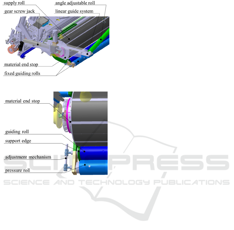
Figure 7: Material buffer in detail.
Figure 8: Material guiding.
In previous test there were two additional issues
according to the material guiding and buffering. De-
pending on the robot position, single textile layers on
the supply roll can lose position by sliding to one side.
By shifting the material layers the occurring offset
also effects the fabric position on the mould. There-
fore a mechanical end stop was added to the supply
roll. Further it has to be considered, that as a result of
moving the angle adjustable roll differently on both
sides, a material guiding is created were one axis is
not parallel to all the other guiding rolls. This can
cause a material drift whose strength and direction de-
pends on the inclination of the angel adjustable roll.
Therefore fixed guiding rolls were added to the end
effector. Design details are shown in Figure 8. One
guiding roll was designed with support edges which
should prevent the material from drifting. The other
roll can press onto the material to prevent wrinkling.
The pressure can be adjusted by a mechanical mech-
anism.
For the control of the material buffer it is im-
portant to know the exact geometrical conditions
within the buffer system. By moving the linear guide
of the material buffer the length of the material edge
changes nonlinear in relation to the axis movement.
Therefore the target position of the two linear guides
of the angle adjustable roll must constantly be calcu-
lated during the applying processes. The exact geo-
metrical calculation is shown in chapter 4.3.
4.3 Capacity Calculation
For simplifying the calculation of the storage capac-
ity, only the two material edge lengths are calculated.
The difference between the edge lengths is the theo-
retical storage capacity. The maximum deflected end
of the roll is, decisive for the maximum length of the
unrolled material. The edge length of the minimally
deflected roll end provides a base value for the calcu-
lation of the edge length change.
Regarding the formulas shown in chapter 4.3, it
was assumed that the minimal radius of the supply
roll r
ma
is greater than the radius of the angle-adjusta-
ble roll r
1
(see Figure 10). The planes of the material
edges intersect the longitudinal axis of the deflected
angle-adjustable roll (see Figure 9). In the following
formulas, a simple circle contour is assumed as a sim-
plification. With the construction, the maximum error
is less than 1 mm.
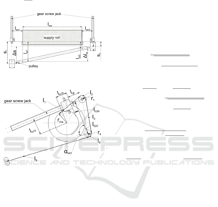
4.3.1 Track Calculation of the Carriage
The length l
gr
is defined as the length between the gear
screw jack and the center of the first roll (see Figure
10). For this purpose, the gear screw jack was pro-
jected into the material edge plane. The length differ-
ence ∆l
gr
of the lengths l
gr2
of the right side and l
gr1
of
the left side (see Figure 9) can be calculated according
to formula (1).
∆l
l
1
l
2
(1)
The calculation of the material edge length is de-
scribed in chapter 4.3.2. All geometrical quantities on
the opposite sides are indicated with the indices 1 or
2 (see Figure 9).
The roll width l
ma
as well as the lengths between
the axis of the gear screw jack and the rolls of material
l
am1
and l
am2
are known. The difference ∆l
gr
must be
calculated beforehand (see chapter 4.3.2). Thus the
stroke change ∆s of the carriage can now be calcu-
lated with formula (2).
ICINCO 2019 - 16th International Conference on Informatics in Control, Automation and Robotics
54
∆
Δl
∙
l
(2)
Figure 9: Geometric quantities for calculating the differ-
ence ∆l
gr
of the lengths l
gr1
and l
gr2
.
Figure 10: Geometric quantities for calculating the lengths
l
1
to l
4
.
With the stroke change ∆s the new stroke s
1
can
be calculated.
∆
(3)
4.3.2 Edge Length Calculation
The illustrated geometric quantities are differentiated
into the types of constructively determined quantities,
measurable quantities and variables. These quantities
are described below.
All geometrical quantities with the index “h” are
auxiliary quantities. These are determined construc-
tively, as well as the radii r
1
and r
4
. The radius of the
supply roll r
ma
can be measured by a sensor or calcu-
lated based on historical values. The length l
gr
is the
length in the material edge plane between an edge of
the projection of the gear screw jack and the centre of
the angle-adjustable roll. The total material edge
length L is calculated with formula (4).
(4)
The equations (5) to (8) describe the calculation of the
lengths shown on Figure 10.
1
cos
arcsin
∙
(5)
2
2∙
1
∙
360
∙ arctan
14
15
arcsin
1
15
14
90arctan
34
31
(6)
3
31
cosarctan
34
31
(7)
4
2∙
4
∙
360
∙180
41
arctan
34
31
(8)
The length l
5
is also a constructive determined
length. All rolls in contact are stationary with respect
to the end effector. According to the geometry of the
mould, the length difference ∆l
gr
per time unit or dis-
tance unit is determined. Due to this length differ-
ence, it is possible to calculate the stroke change ∆s,
necessary in this unit, according to equation (2).
With the given quantity L of the length of the ma-
terial edge of the roll, the implicitly contained quan-
tity l
gr
can be calculated with equation (9).
0
(9)
This can be done, for example, with the help of
the zero approximation method named “false position
method” or “Regular Falsi”. This method is described
in (Bronstein et al., 2008) and (Kiusalaas, 2013).
These calculations can be done by the robot control-
ler.
Automated Draping of Wide Textiles on Double Curved Surfaces
55
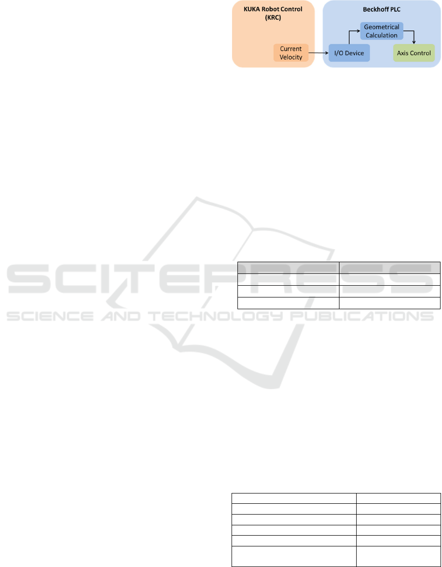
4.4 Control Architecture
The control architecture for the experimental investi-
gation is as follows. The industrial robot with its lin-
ear axis is controlled by the KUKA Robot Control
(KRC). All other actors and axis of the end effector
as well as the axis for the material buffer are con-
trolled by a PLC. The communication between the
KRC and the PLC goes via EtherCAT. Since both
systems act as masters, there is a master/master bridge
between them. For controlling the material buffer
there are three points that need to be considered:
Robot Speed. For buffering the correct amount of
material it is important that the axis movement of the
material buffer is synchronised to the velocity of the
TCP. The synchronisation is done via the submit in-
terpreter of the KUKA robot by transmitting the cur-
rent robot speed (speed of the TCP).
Geometric Characteristics of the Mould. Further, it
is important to consider the geometric characteristics
of the mould for the deflection of the material buffer.
For calculating the axis movement in context of the
length difference between the material edges one has
to consider the ratio of the side lengths and the length
of the TCP path for calculating the axes speeds.
Therefore a CAD based plybook contains the target
positions of all plies. Out of this plybook a CSV file
was created with the 3D length information of the two
material edges and the TCP path. With this infor-
mation it is possible to calculate the target position of
each material buffer axis. In order to achieve an exact
material buffering not only the target position but also
the buffering speed is decisive. For this purpose the
three paths were divided into equal pieces with a de-
fined length and imported into the CSV. During the
deposition process a position counter detects the cur-
rent sequence and transfers the length information
into the geometrical calculation part of the software.
There a geometrical induced offset is calculated for
controlling the two axes speeds of the material buffer.
This approach provides some inaccuracies related to
the number of pieces in which the path is divided, but
it is a good approximation of reality. The calculations
become more accurate by an increasing number of de-
nominations.
Geometric Characteristics of the Material Buffer.
Locking at the mechanical design of the material
buffer (chapter 4.2) it is clear, that the axis movement
of the buffer is neither equal nor linear to the buffered
material length. Therefore it is necessary to calculate
the axis movement in consideration of the geomet-
rical behaviour of the material buffer. A more detailed
description of the calculations is described in (chapter
4.3). Figure 11 shows the control architecture for the
material buffer.
Figure 11: Schematic sketch of the control structure for the
adaptable material buffer.
5 VA L I D AT I O N
The adaptable material buffer was validated in an ex-
perimental investigation
5.1 Setup and Implementation
For validating the material buffer an exemplary ply
(P0011) was chosen. Table 1 shows the basic geomet-
rical characteristics of ply P0011.
Table 1: Geometrical characteristics of the ply P0011.
Pl
y
No. P0011
L1 3599 m
m
L2 4060 m
m
Len
g
th difference 461 m
m
For increasing the adhesion, a thin film of epoxy
resin was sprayed onto the mould surface. The ply
was at first laid up without using the buffer system.
After that the mould was cleaned and the resin film
was renewed. Then the same ply was laid up by using
the material buffer. The process parameters are
shown in Table 2. Apart from the buffering, all other
settings remained the same, including the Parameters
of the geometrical velocity offset for the draping rolls
as well as the robot speed and the amount of resin.
The general setup for the experimental investigation
is shown in Figure 4.
Table 2: Process parameters of the experimental investiga-
tion.
Fabric type Satin wave
Material width 50 inch
Wei
g
ht
p
er unit area 370
g
/m²
Process spee
d
0,1 m/s
Layer fixation Yes (epoxy resin)
Velocity offset for the drives of
the dra
p
in
g
roll
Yes
ICINCO 2019 - 16th International Conference on Informatics in Control, Automation and Robotics
56
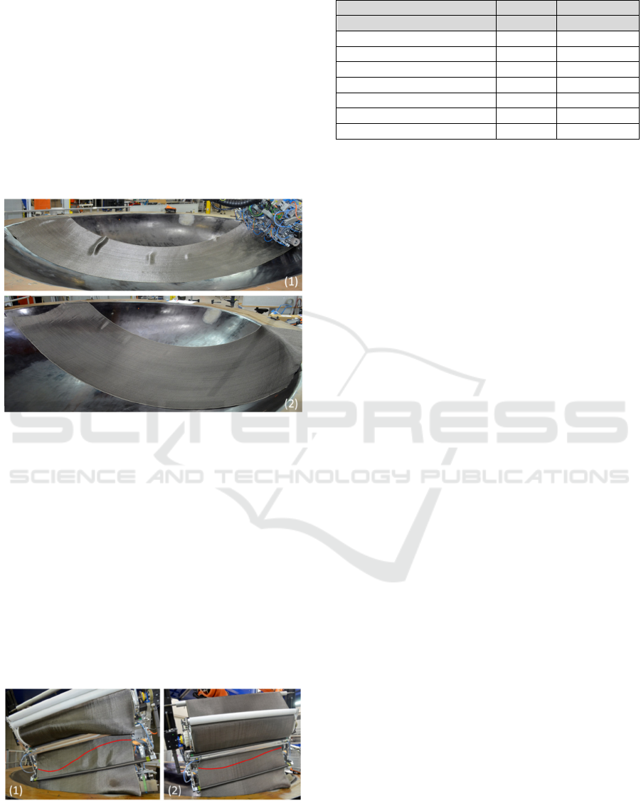
5.2 Results
The results of the experimental investigation are
shown in Figure 12. Picture (1) shows the ply deposi-
tioned without using the material buffer. There are
four out of plane defects (waves). The first wave is a
large one on the left side in picture (1). The second
one is a midrange wave in the middle of the ply and
the last two waves located in the rear section are quite
small. Picture (2) shows the ply depositioned by using
the material buffer. One can see a small wave at the
beginning of the ply. The rest of the ply is without any
defects.
Figure 12: Results without buffer (1), with buffer (2).
Figure 13 shows the condition of the material in
the end effector after finishing the layup. Picture (1)
shows the end effector after applying the fabric with-
out using the material buffer. One can see the loosley
material tension in between the guiding rolls by the
accumulation of the surplus material on the right. Fur-
ther one can see the strongly distorted fibre angel
roughly indicated by the red line. Picture (2) shows
the end effector after applying the fabric by using the
material buffer. One can see the material with more
tension and less surplus material. Also the distortion
of the fibre angle is less, indicated by the red line. A
summary of the experimental results is shown in Ta-
ble 3.
Figure 13: Material tension and fibre angle without buffer
(1) and with buffer (2).
Table 3: Results of the experimental investigation.
Pl
y
No. P0011 P0011
Material Buffe
r
y
es no
Material tension ti
g
ht loosel
y
Fibre distortion small high
Out of plane defects:
Numbe
r
1 4
T
yp
e / Classification wave wave
Size small
b
i
g
- small
Location start continuous
6 DISCUSSION
The implementation of the adaptable material buffer
improved the results of depositioning wide textiles
onto double curved surfaces. It could be shown, that
the material guiding in between the end effector im-
proved. The material tension was higher and less sur-
plus material was left in the end effector Figure 13.
Also undesired shearing of fibre angles within the end
effector has been reduced.
But there are also disadvantages that have to be
mentioned. As described in chapter 4.2, inserting an
inclined axis causes a material drift. The strength and
direction of this drift strongly depends on the angle
between the buffer axis and the other guiding rolls.
Also the implemented support edge could not com-
pletely prevent the material drift. By using the buffer
system in its rear workspace this undesired material
movement can be reduced, but not completely
avoided. This would require an online position cor-
rection of the robot movement.
Additionally there are still small waves on the ply
were at least the bigger one would be critical in the
industrial production. One reason that could be deter-
mined was an influence of the buffer system on the
supply roll. For providing a constant tension the sup-
ply roll is controlled by a torque limitation. By mov-
ing the angle adjustable guiding roll of the buffer sys-
tem an additional force acts on the supply roll. This
force can lead to an increasing output of material
which causes waviness. Therefore an improvement of
the control settings for both systems (material buffer
and supply roll) is necessary.
Further it has to be mentioned that the experi-
mental results shown in Figure 12 were both reached
with the use of a geometrical velocity offset on the
drives of the draping roll. It has to be pointed out, that
the use of just one of these two methods would not be
enough to reach proper results. The geometrical ve-
locity offset for the draping roll will be presented in a
further work.
Automated Draping of Wide Textiles on Double Curved Surfaces
57

7 CONCLUSION
In this paper a buffer system is introduced that acts as
an assisting system for the automated draping of tex-
tiles. The issue of length differences when deposition-
ing textiles on double curved surfaces is addressed.
As a solution, an adaptable material buffer which can
independently control the two edge lengths of the fab-
ric during the application process is proposed. For this
solution the mechanical design, the control architec-
ture and the mathematical background for controlling
the buffer system are presented. The suggested ap-
proach was implemented and evaluated by an experi-
mental investigation. The results were emphasized
and improvements like layup quality, material guid-
ance as well as the occurring disadvantages are dis-
cussed. Future works have as goal the improvement
of the interaction between the supply roll and the
buffer system, as well as the correction of the material
drift by deflecting the adjustable roll of the material
buffer. The geometrical velocity offset, passed onto
the drives of the draping roll, must also be fully inte-
grated. Nevertheless the present approach is a prom-
ising solution which can contribute to the automated
draping of textiles.
REFERENCES
Black, S. 2003. Precision Feed End-Effektor composites
fabric tape-laying apparatus and method. High
Performance Composites Magazine.
Black, S. 2009. Automating wind blade manu-facture.
Composites World.
Bronstein, I. N., Semendjajew, K. A., Musiol, G. & Mühlig,
H. 2008. Taschenbuch der Mathematik. 7., vollstän-dig
überarbeitete und ergänzte Auflage. Frankfurt am
Main: Verlag Harri Deutsch.
Croft, K., Lessard, L., Pasini, D., Hojjati, M., Chen, J. H. &
Yousefpour, A. 2011. Experimental study of the effect
of automated fiber placement induced defects on
performance of composite laminates. Composites Part
a-Applied Science and Manufacturing, 42, 484-491.
Ehinger, C. A. 2013. Automatisierte Montage von Faser-
verbund-Vorformlingen. Dissertation, Technischen
Universität München.
Elkington, M., Ward, C. & Sarkytbayev, A. 2017.
Automated composite draping - A review. SAMPE
2017. SAMPE North America.
Gardiner, G. 2011. A350 XWB update: Smart manufacturing.
High-performance compos-tes, 19(5), 54-60.
Groppe, D. 2007. Precision Feed End-Effektor composites
fabric tape-laying apparatus and method. United States
patent applica-tion 10/661,383.
kiusalaas, J. 2013. Numerical methods in engineering with
Python 3, Cambridge university press.
Kozaczuk, K. 2016. Automated Fiber Placement Systems
Overview. Transactions of the Institute of Aviation,
245, 52-59.
Lukaszewicz, D. H. J. A., Ward, C. & Potter, K. D. 2012.
The engineering as-pects of automated prepreg layup:
History, present and future. Composites Part B:
Engineering, 43, 997-1009.
Manson, J.-A. E., Rozant, O. & Bourban, P.-E. 2000.
Drapability of dry textile fa-brics for stampable
thermoplastic preforms. Composites Part A: Applied
Science and Manufacturing(UK), 31, 1167-1177.
Marsh, G. 2011. Automating aerospace composi-tes
production with fibre placement. Rein forced Plastics,
55, 32-37.
Müller, D. H. 2007. Projekt PRO-CFK, Techni-scher
Abschlussbericht.
Niefenecker, D. 2014. Azimut - Automatisie-rung
zukunftsweisender industrieller Me-thoden und
Technologien für CFK-Rümpfe. Abschlussbericht.
Ohlendorf, J.-H., Rolbiecki, M., Schmohl, T., Franke, J. &
Ischtschuk, L. 2014. mapretec - ein Verfahren zur
preform-Herstellung durch ebene Ablage für ein
räumliches Bauteil als Basis einer automatisierten
Prozesskette zur Rotorblattfertigung.
Olsen, H. B. & Craig, J. J. Automated composi-te tape lay-
up using robotic devices. [1993] Proceedings IEEE
International Conference on Robotics and Automation,
1993. IEEE, 291-297.
Richrath, M., Franke, J., Ohlendorf, J.-H. & Thoben, K.-D.
2017. Effektor für die automatisierte Direktablage von
Textili-en in der Rotorblattfertigung. Lightweight
Design, 10, 48-53.
Schmidt-Eisenlohr, C., Kaufmann, P., Sonnenberg, M. &
Malecha, M. 2019. Optimised trajectory calculation for
the automated layup of wide lightning protection tapes
on double-curved fuselage sections. Composite
Structures, 210, 906-913.
Schnitzer, M. 2013. Anforderungen und Lösungsansätze
für einen höheren Automa-tisierungsgrad in der CFK-
Fertigung. 2. Augsburger Produktionstechnik-
Kolloqui-um. Augsburg.
Sloan, J. 2008. ATL and AFP: Defining the megatrends in
composite aerostructures. Composites World.
Szcesny, M., Heieck, F., Carosella, S., Middendorf, P.,
Sehrschön, H. & Schneiderbauer, M. 2017. The
advanced ply placement process – an inno-vative direct
3D placement technology for plies and tapes. Advanced
Manufacturing: Polymer & Composites Science, 3, 2-
9.
Wade, J. 2012. The effect of tow grouping resolu-tion on
shearing deformation of unidirec-tional non-crimp
fabric. Master of Science.
Weigel, L. & Müller, D. H. 2007. PREBLADE -
Gemeinsamer Technischer Abschlussbe-richt.
Zhu, S. 2015. An automated method for the layup of
fiberglass fabric. Dissertation, Iowa State University.
Zhu, S., Magnussen, C. J., Judd, E. L., Frank, M. C. &
Peters, F. E. 2017. Automated Composite Fabric Layup
for Wind Turbine Blades. Journal of Manufac-turing
Science and Engineering, 139.
ICINCO 2019 - 16th International Conference on Informatics in Control, Automation and Robotics
58
