
Modeling and Simulation of Attacks on Cyber-physical Systems
Cinzia Bernardeschi
1 a
, Andrea Domenici
1 b
and Maurizio Palmieri
2 c
1
Department of Information Engineering, University of Pisa, Pisa, Italy
2
Department of Information Engineering, University of Florence, Florence, Italy
Keywords:
Security, Cyber-physical attacks, Co-simulation.
Abstract:
This paper presents a methodology for the formal modeling of security attacks on cyber-physical systems,
and the analysis of their effects on the system using logic theories. We consider attacks only on sensors and
actuators. A simulated attack can be triggered internally by the simulation algorithm or interactively by the
user, and the effect of the attack is a set of assignments to the variables. The effects of the attacks are studied
by injecting attacks in the system model and simulating them. The overall system, including the attacks,
the system dynamics and the control part, is co-simulated. The INTO-CPS framework has been used for
co-simulation, and the methodology is applied to the Line follower robot case study of the INTO-CPS project.
1 INTRODUCTION
Model-based design of cyber-physical systems (CPS)
allows to analyze the system behavior before a phy-
sical prototype of the system is built. Simulation is
one of the techniques that are usually applied together
with testing in the analysis of systems behaviors. In
the case of cyber-physical systems, simulation often
takes place in the form of co-simulation, which allows
sub-systems, each modeled with its most appropriate
languages and tools, to be composed together. The
main advantage of co-simulation is modeling flexibi-
lity, because it does not require a single modeling lan-
guage for all system parts (e.g., discrete and continu-
ous parts). The Functional Mockup Interface (FMI)
(Blochwitz et al., 2012) is an emerging standard for
co-simulation of cyber-physical systems.
Moreover, model-based design based on for-
mal methods reduces development costs and enables
proofs of correctness for the system. Formal methods
have been used intensively in the past in the develop-
ment of safety-critical systems, and they are also as-
suming a fundamental role in the security field. The
main advantage of formal methods in the field of se-
curity is that they are the only technique that can be
used to formally prove resilience to attacks. For ex-
ample, (Meadows, 2003) reports on the history of ap-
a
https://orcid.org/0000-0003-1604-4465
b
https://orcid.org/0000-0003-0685-2864
c
https://orcid.org/0000-0002-6177-0928
plication of formal methods to cryptographic protocol
analysis, and in (Avvenuti et al., 2012) abstract inter-
pretation was applied to certify programs for secure
information flow.
A recent survey by Humayed et al. (Humayed
et al., 2017) reports on a large number of publicati-
ons from the literature on CPS security and proposes
a classification framework based on three orthogonal
criteria: security, with the categories of threats, vul-
nerabilities, attacks, and controls; components, with
the categories of cyber, physical, and cyber-physical
components; and systems, with categories related to
general system characteristics, such as architecture or
application field.
Burmester et al. (Burmester et al., 2012) describe
a formal model for CPS security based on hybrid ti-
med automata and the Byzantine fault model, using
an international natural gas distribution grid as an ex-
ample.
The notion of impact metric for cyber-physical at-
tacks is introduced by Lanotte et al. (Lanotte et al.,
2018), who establish a theoretical framework built on
weak bisimulation metrics.
Ferrante et al. (Ferrante et al., 2014) approach the
issue of security requirements specification for em-
bedded systems by defining a UML profile and deve-
loping an automatic process to generate system requi-
rements from user requirements.
Formal method have already been applied for fault
injection and simulation of the system after the occur-
rence of faults (Butler et al., 2009; Bernardeschi et al.,
700
Bernardeschi, C., Domenici, A. and Palmieri, M.
Modeling and Simulation of Attacks on Cyber-physical Systems.
DOI: 10.5220/0007705307000708
In Proceedings of the 5th International Conference on Information Systems Security and Privacy (ICISSP 2019), pages 700-708
ISBN: 978-989-758-359-9
Copyright
c
2019 by SCITEPRESS – Science and Technology Publications, Lda. All rights reserved

2014). In this paper, we propose a similar approach
for the analysis of system security. The PVS tool,
a specification, verification, and simulation environ-
ment based on higher-order logic, is used for the spe-
cification of the control part of CPSs. Then the INTO-
CPS co-simulation framework (Larsen et al., 2016) is
used to generate simulation traces of the overall sy-
stem. Preliminary results on a case study (a simple
robot vehicle) are presented.
The paper is organized as follows: Section 2
briefly describes the PVS framework, and the co-
simulation framework; Section 3 describes our met-
hodology to formally model an attack; Section 4
shows an application of the method, using a Line Fol-
lower robot as a case study (the theory of the line fol-
lower robot, the theories of the modeled attacks and
results of the co-simulation are presented); Section 5
concludes the paper.
2 BACKGROUND
2.1 The PVS Environment
The Prototype Verification System (PVS) (Owre et al.,
1992) is an interactive theorem-proving environment
whose users can define theories in a higher-order logic
language and prove theorems with respect to them.
The language of PVS is a purely declarative language,
but its PVSio extension (Mu
˜
noz, 2003) can translate
PVS function definitions into Lisp code, so that a PVS
expression denoting a function application with fully
instantiated arguments can be interpreted as an impe-
rative function call. The PVSio extension includes in-
put/output functions allowing the system prototype to
interact with the user and the computing environment.
Moreover, MisraC code can be automatically gene-
rated from PVS theories for automata (Masci et al.,
2014; Mauro et al., 2017), using the PVSio-web tool-
set (Oladimeji et al., 2013).
The PVS specification language provides basic ty-
pes, such as Booleans, naturals, integers, reals, and
others, and type constructors to define more complex
types. The mathematical properties of each type are
defined axiomatically in a set of fundamental theo-
ries, called the prelude. Among the complex types,
the ones used in this work are record types and predi-
cate subtypes.
A record is a tuple whose elements are referred to
by their respective field name. For example, given the
declarations:
wheels: TYPE = [#
left: Speed,
right: Speed #]
axle: wheels =
(# left := 1.0, right := 2.0 #)
axle is an instance of type wheels and the ex-
pressions left(axle) and right(axle) denote the
speeds of the left and right wheels of axle, re-
spectively. Equivalent notations are axle‘left and
axle‘right.
The overriding operator := in a WITH expression
redefines record fields. With the declarations above,
the expression
axle WITH [ left := -1.0 ]
denotes the record value (#-1.0, 2.0#).
An example of predicate subtype is the following:
LightSensorReading: TYPE =
{ x: nonneg_real | x <= 255 }
which represents the real numbers in the [0, 255]
interval.
The PVS syntax includes the well-known logical
connectives and quantifiers, besides some constructs
similar to the conditional statements of imperative
languages. These constructs are the IF ... ENDIF
expression and the COND ... ENDCOND expression.
The latter is a many-way switch composed of clauses
of the form condition → expression where all condi-
tions must be mutually exclusive and cover all possi-
ble combinations of their truth values (an ELSE clause
provides a catch-all). The PVS type checker ensures
that these constraints are satisfied.
Definitions within a given theory may refer to de-
finitions from other theories. This makes it possible
to build complex system specifications in a modular
and incremental way. Theory control th below im-
ports robot th and defines functions for controlling
the robot.
robot_th: THEORY
BEGIN
id: posnat
State: TYPE [# ... #]
....
END robot_th
control_th: THEORY
BEGIN IMPORTING robot_th
ACC_STEP: Speed = 0.1
accelerate(st: State): State
BRAKE_STEP: Speed = 0.05
brake(st: State): State
...
END control_th
The PVS environment includes the NASALIB
theory libraries (Dutertre, 1996) providing axioms
and theorems addressing many topics in mathematics,
including real number analysis, and it can be applied
to model both the discrete and the continuous part of
the system (Bernardeschi and Domenici, 2016).
Modeling and Simulation of Attacks on Cyber-physical Systems
701
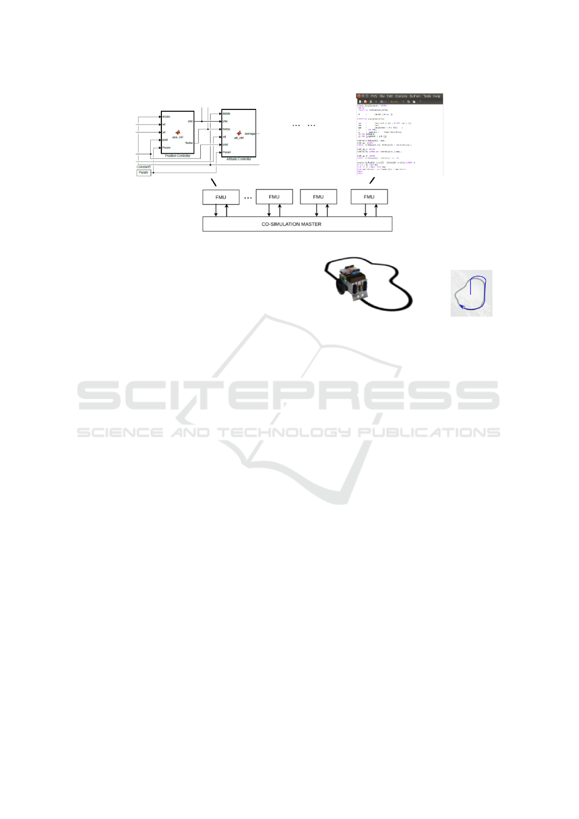
Figure 1: FMI architecture.
2.2 The Co-simulation Framework
Co-simulation is the joint simulation of independent
sub-models each representing a component or subsy-
stem of the overall system.
In the FMI standard (Blochwitz et al., 2012), co-
simulation is performed by a number of Functional
Mockup Units (FMUs), each responsible for simula-
ting a single model in the native formalism with the
tool used to create the model. The FMI architecture is
shown in Figure 1.
An FMI-compliant environment provides a Co-
Simulation Engine (COE) that communicates with
FMUs, in a master-slave configuration to exchange
data.
The COE and the FMU exchange commands and
data using buffers in the FMU. The COE invokes (i)
fmi2Set() for updating the values of the input varia-
bles in the buffers of the FMU; (ii) fmi2DoStep() for
the execution of a co-simulation step. This function
copies the values of the input variables from the FMU
buffers to the PVS state; invokes the simulator and co-
pies the values of the output variables from the PVS
state to the buffers; (iii) fmi2Get() to get the new
values of the output variables from the buffers of the
FMU.
INTO-CPS (Bagnato et al., 2015; Larsen et al.,
2016) is a co-simulation environment that integrates
tools for the engineering of cyber-physical systems,
covering both modeling of discrete and continuous
behaviors and formal proofs.
Examples of tools available in INTO-CPS for mo-
deling and analysis are Modelio (modelio, 2018),
Overture (Larsen et al., 2010), and 20-sim (Broenink,
1999).
In (Palmieri et al., 2017), the authors extended
the INTO-CPS co-simulation framework with FMUs
that allow user interaction in the co-simulation. Such
FMUs are based on the PVS tool and implement the
interface using PVSio-web (Oladimeji et al., 2013).
Figure 2: The Line Follower robot (INTO-CPS project
http://projects.au.dk/into-cps/) and an example of a robot
trajectory.
The Line Follower robot is a small vehicle that
can follow a path defined by a black line painted on
a white floor. Figure 2 shows a practical realization
of the robot and a visual rendition of a simulated path
superimposed on the expected path.
Figure 3 shows the co-simulation framework for
the INTO-CPS Line Follower robot case study with
automatic and manual control.
The FMU for the controller of the robot is mo-
deled in PVS and the user interface for the robot is a
joystick (a picture of a real device with PVS functi-
ons assigned to widgets and displays). The FMU that
contains only the back-end of PVSio-web, while the
front-end of PVSio-web is implemented as an exter-
nal module which communicates with the FMU.
The user can acquire control of the robot from the
joystick, manually control the robot with buttons, and
switch the robot back to automatic control. On the
right hand side of the joystick, the path followed by
the robot is shown. In the developed environment, a
real joystick could also be used in the co-simulation
instead of the virtual one. The case study is better
explained in Section 4.
3 MODELING ATTACKS
The behavior of a cyber-physical system consists of a
control loop, finalized at controlling the physical part
according to control laws. At each cycle of the loop,
ForSE 2019 - 3rd International Workshop on FORmal methods for Security Engineering
702
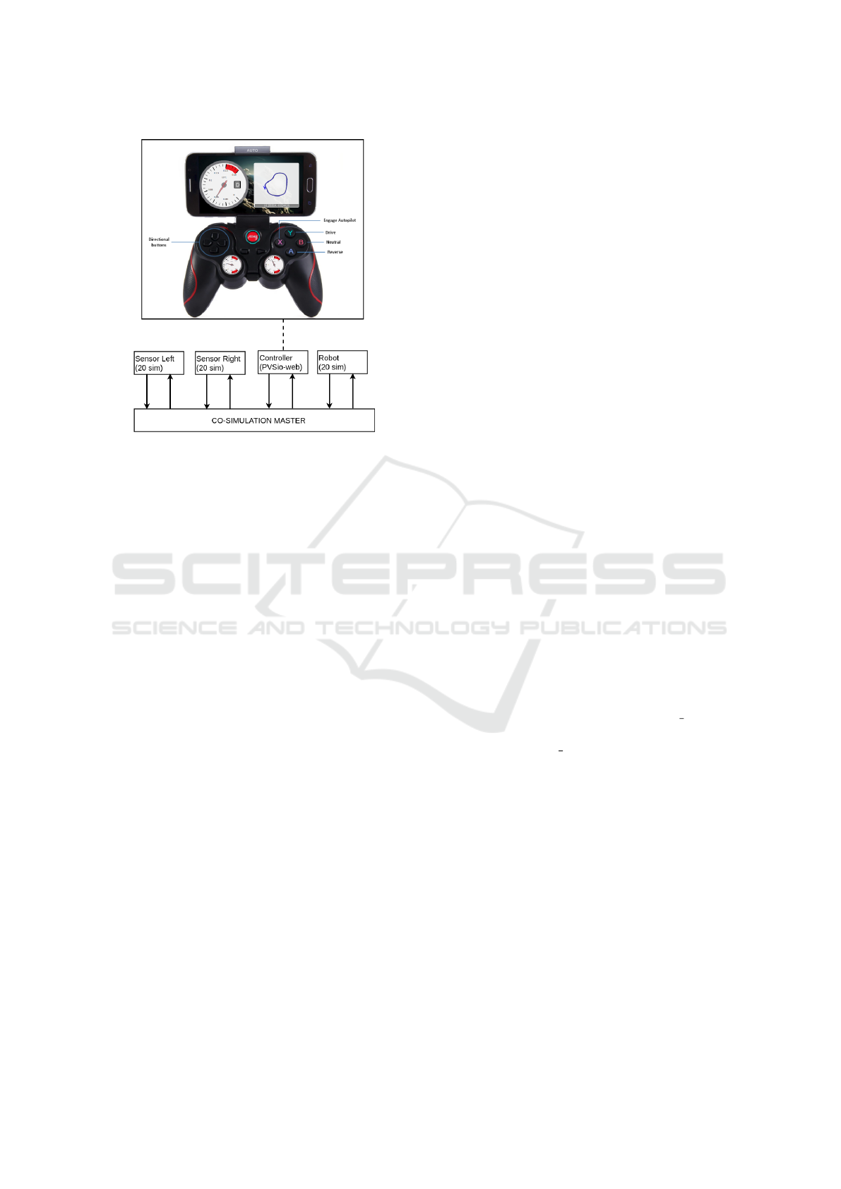
Figure 3: Architecture of interactive FMUs.
sensors in the plant send data to the controller, which
acts on the plant sending commands to the actuators.
In the FMI framework, the Controller and the
Plant are FMUs, and the COE links outputs of the
Plant FMU with inputs of the Controller, and vice-
versa.
We assume the Controller FMU is formally descri-
bed in the PVS language. The specification consists
of two basic elements: the state of the sub-system
(State) and the function tick(State):State,
which given a state, according to control laws, com-
putes the output to be forwarded to other sub-systems.
In particular, data read from sensors in the Plant
FMU are put into the input variables of the state of
the Controller. Data computed by the Controller for
the actuators are stored into the output variables of the
state of the Controller.
In this work, we consider the following types of
attacks:
• Attack to sensors. The effect of such an attack is
the corruption of data read from sensors. At the
beginning of each co-simulation step, such data
are stored into the input variables of the Control-
ler’s state.
• Attack to actuators. The effect of such an attack is
the corruption of data sent to actuators. At the end
of each co-simulation step, such data are stored
into the output variables of the Controller’s state.
The FMU of the Control part is modified as fol-
lows:
- Each attack is modeled by a function that alters
the system state according to the attack’s envisio-
ned effects.
- For each attack, the time of the occurrence of the
attack must be specified, distinguishing between
permanent attacks, or temporary attacks, and, in
that case, distinguishing between sporadic attacks
or attacks executed only once.
- An attack can be simulated in two ways: (i) It
can be generated internally by the simulation al-
gorithm, or (ii) it can be activated interactively by
the user (i.e., the developer in charge of perfor-
ming the simulation).
In particular, an attack A is formally specified by
a set of state variables, a set of clocks and a set of
guarded statements:
A = hVar
A
, Clk
A
∪ {stepCounter}, Com
A
i
• State variables. Var
A
is the set of variables of the
state of the controller that are accessed by the at-
tacker.
• Clocks. Two types of clocks are used: a set
Clk
A
of attacker clocks and a global clock ste-
pCounter, which is initialized to 0 when a co-
simulation run starts; and it is incremented for
each co-simulation step. The attacker cannot mo-
dify this global clock.
• Guarded statements. Com
A
is a set of guarded sta-
tements. A guarded statement has the form:
[condition → x
1
:= v
1
;· ·· ; x
n
:= v
n
], where
condition, the guard of the statement, is a condi-
tion on clocks (using logical operators ∧, ∨, =,
6=); and the statement is a sequence of assign-
ments to state variables or to local clocks (x
i
:=
v
i
;), x ∈ Var
A
∪Clk
A
). Guards must be mutually
exclusive.
To model attacks, we extend the state of the sy-
stem in the Controller as follows: ext
State is
State extended with stepCounter and with the set
of local clocks Clock
A.
The effects of the attack are described by a
function in PVS, whose skeleton is described below:
fun_attack(st: ext_State): ext_State =
IF condition
THEN st
WITH [x1 := v1,
...,
xn := vn
]
ELSE st
ENDIF
Some possible attacks could be:
- every 20 simulation steps, increment by 3 the
value read from a sensor;
- every 100 simulation steps, lock at zero the value
sent to an actuator for 20 steps;
Modeling and Simulation of Attacks on Cyber-physical Systems
703

- double the value of a sensor randomly in the co-
simulation.
A local clock is used to count the number of steps
between two attacks; and two local clocks are used to
model the lock-at-zero attack, one to count the dura-
tion of the attack and another to count the steps bet-
ween two attacks.
Probabilistic behaviors can be encoded in at-
tacks using the function NRANDOM(n: posnat):
below(n), which is available in the PVS framework
and that implements a uniform pseudo-random num-
ber generator that returns a natural number in the in-
terval [0::n). Using the language of PVS, more so-
phisticated attacks could also be implemented.
3.1 Attacks Generated Internally by the
Simulation Algorithm
Let Sensor attack be a function modeling an attack
to sensors. The behavior of the system under attack is
specified as the result of the function tick() on the
extended state of the system after the attack to sen-
sors:
system_under_attack(st: ext_State) :
ext_State =
LET st1 = Sensor_attack(st),
IN tick(st1)
We assume that ext State is the state of the sy-
stem with the addition of a variable for each clock
defined in the model of the attacks, and tick() is the
function applied by the controller. The LET ... IN
... construct introduces a definition to be used in the
expression following IN.
Let Actuator attack be a function modeling an
attack to actuators, the behavior of the system un-
der attack is specified as the result of the function
Actuator attack on the state of the system gene-
rated by the function tick().
system_under_attack(st: ext_State) :
ext_State =
LET st1 = tick(st)
IN Actuator_attack(st1)
Finally, the two attacks could be combined. Since
attacks to sensors affect the inputs to the con-
troller and attacks to actuators affect its outputs,
system under attack first passes the current state
to the function modeling sensor attacks, then the re-
sulting state is passed to the controller, which com-
putes another state that is further transformed by the
function modeling actuator attacks, as shown in the
following code.
system_under_attack(st: ext_State) :
ext_State =
LET st1 = Sensor_attack(st),
st2 = tick(st1)
IN Actuator_attack(st2)
3.2 Attacks Activated Interactively by
the User
Another approach to activate attacks in the co-
simulation is through the creation of an HTML page
that is able to connect with the FMU and to invoke dif-
ferent functions. When the HTML page is open on a
web-browser, the function that represents the attack is
invoked at each co-simulation step. This implementa-
tion uses the PVSio-web (Oladimeji et al., 2013) tool,
which allows us to create the graphical interface of a
device and to link interface elements with functions
describing how the device responds to user actions.
When an action is executed (e.g. user clicks a but-
ton or a timer expires), a JavaScript module sends the
appropriate command to the PVS FMU that executes
the action in the co-simulation step. In our case, the
command is “execute fun attack() before tick()”
or “execute fun attack() after tick()” depending
on the type of attack (i.e., attack to sensors or attack to
actuators). When an attack is activated interactively, it
is independent of the current co-simulation timestep,
and the attack is only active when the HTML page is
open. When the HTML page is closed the simulated
system is no longer under attack. As a consequence,
it is possible to change the number and the duration
of the attacks during a co-simulation run.
4 A CASE STUDY
The system considered in this work is the Line
Follower robot case study of the INTO-CPS pro-
ject (http://projects.au.dk/into-cps/), see Figure 2 in
Section 2. The robot has two drive wheels each pro-
pelled by its own independent motor, and two opti-
cal sensors, symmetrical with respect to the longitu-
dinal axis, that measure the reflected light intensity
of the floor immediately ahead of the robot. The ro-
bot starts astride the black line, so that both sensors
see the white floor. The robot keeps heading forward
as long as both sensors detect a white color. When
the path curves, one sensor intercepts the black line
while the other still sees the white floor. The robot
controller then steers the vehicle by slowing down the
internal wheel (on the side of the sensor detecting the
line) with respect to the external one.
In addition to the automatic mode of operation,
it is possible for a human to override the automatic
control and drive the robot with a remote dashboard,
ForSE 2019 - 3rd International Workshop on FORmal methods for Security Engineering
704

in our implementation a joystick console is used (see
Figure 3 in Section 2).
4.1 Robot Theory
In the following, we show the main parts of a PVS
theory describing the above system.
First, some type definitions provide the types
of data needed for the model: CruiseControl
to distinguish the two modes of operation,
LightSensorReading to specify the values from
the sensors, LightSensors to access the left and
right sensor readings, Speed to specify the angular
speed range for the wheels, MotorSpeed to access
or control the two wheel motors, and Gear to dis-
tinguish the three modes of the gear train. Positive
and negative speed values represent clockwise and
counterclockwise rotation, respectively.
robotUI: THEORY
BEGIN
CruiseControl: TYPE = { AUTO, MANUAL }
LightSensorReading: TYPE =
{ x: nonneg_real | x <= 255 }
LightSensors: TYPE = [#
left: LightSensorReading,
right: LightSensorReading
#]
Speed: TYPE =
{ x: real | x >= -1 AND x <= 1 }
MotorSpeed: TYPE = [#
left: Speed,
right: Speed
#]
%-- gears
Gear: TYPE = { DRIVE, REVERSE, NEUTRAL }
Data of the above types compose the system state,
plus a real value representing time:
State: TYPE =
[# lightSensors: LightSensors,
motorSpeed: MotorSpeed,
gear: Gear,
time: real,
cc: CruiseControl #]
The control algorithm is specified by functions
that update the system state by setting the motor speed
depending on the sensor readings. In the two follo-
wing functions, a reading of 150 units is chosen as the
threshold between a light (white) and a dark (black)
light intensity. Note that for each combination of rea-
dings, the two motors have opposite speed values, due
to the mechanical arrangement.
update_left_motor_speed(st: State): Speed =
LET ls = lightSensors(st) IN
COND ls‘right < 150 AND ls‘left < 150->0.4,
ls‘right > 150 AND ls‘left < 150->0.5,
ls‘right < 150 AND ls‘left > 150->0.1,
ELSE -> motorSpeed(st)‘left
ENDCOND
update_right_motor_speed(st: State): Speed =
LET ls = lightSensors(st) IN
COND ls‘right < 150 AND ls‘left < 150->-0.4,
ls‘right > 150 AND ls‘left < 150->-0.1,
ls‘right < 150 AND ls‘left > 150->-0.5,
ELSE -> motorSpeed(st)‘right
ENDCOND
The simulation is driven by a tick() function that
is called at each simulation step to update the motor
speeds and increment time:
tick(st: State): State =
IF cc(st) = AUTO
THEN st WITH [motorSpeed := (#
left := update_left_motor_speed(st),
right := update_right_motor_speed(st)#),
time := time(st)+0.01 ]
ELSE st WITH [time := time(st)+0.01]
ENDIF
Finally, the theory defines functions (not shown)
called from the user interface to switch between au-
tomatic and manual control, and in the latter case to
execute user requests, such as accelerating, decelera-
ting, or steering.
Figure 3 in Section 2 shows the results of the co-
simulation when the system is co-simulated for 20 s,
assuming a co-simulation step of 0.01.
4.2 Attack Theories
An attack is injected into the system by executing the
controller together with the functions modeling at-
tacks. In order to model attacks, the robot state is
extended with fields characterizing the different types
of attacks. In the present example, two types of at-
tack are considered: (i) Attack to sensors, occurring
once and acting indefinitely and (ii) Attack to actu-
ators, occurring sporadically with a duration of one
simulation step.
Attack to Sensors. The following function im-
plements an attack that forces to white the value
read by the left sensor indefinitely starting from
a co-simulation step chosen randomly. Function
NRANDOM in the initial state is invoked with an up-
per bound of 500.
Variable lightSensors is modified (140 is the
constant for white color); Clock clk1 specifies the co-
simulation step at which the attack starts.
Var
Sensor attack
= {lightSensors}
Modeling and Simulation of Attacks on Cyber-physical Systems
705

Clock
Sensor attack
= {clk1, stepCounter}
Com
Sensor attack
is the body of the following
function.
Sensor_attack(st: ext_State):
ext_State =
IF stepCounter(st) >= clk1(st)
THEN st
WITH [lightSensors := (#
left := 140,
right := st‘lightSensors‘right #)
]
ELSE st
ENDIF
Attack to Actuators. The following function imple-
ments an attack that sporadically switches off the po-
wer of each motor for one co-simulation step. The
co-simulation step, at which the power of each mo-
tor is switched off, is chosen randomly. Function
NRANDOM in the initial state is invoked with 500.
Then, function NRANDOM is invoked with an upper
bound of 20.
Clock clk2 specifies the co-simulation step at
which the next occurrence of the attack starts; Clock
clk3 counts the number of co-simulation steps since
the last attack. Clock clk3 is reset at zero when the
attack is executed.
Var
Actuator attack
= {motorSpeed}
Clock
Actuator attack
= {clk2, clk3, stepCounter}
Com
Actuator attack
is the body of the following
function.
Actuator_attack(st: ext_State):
ext_State =
IF clk2(st) = clk3(st) THEN
st WITH [motorSpeed := (#
left := 0,
right := 0 #),
clk2 := NRANDOM(20)+1,
clk3 := 0
]
ELSE
st WITH [ clk3 := clk3 + 1 ]
ENDIF
The new state (and the initial state) of the line fol-
lower robot under attack is the following:
ext_State: TYPE =
[# // robot state
// .... omitted
// global clock
stepCounter:int,
// attack to sensors
clk1: int,
// attack to actuators
clk2: int,
clk3: int
#]
In the initial state, the step at which the attacks
start is initialized with a random value:
init_state: State =
(# // robot state
// .... omitted
// global clock
stepCounter := 0;
// attack to sensors
clk1 = NRANDOM(500),
// attack to actuators
clk2: NRANDOM(500),
clk3: 0
#)
Function tick() implements the controller as
previously shown, except that it is redefined on the
extended state, and contains the update of the global
clock (stepCounter).
tick(st: ext_State): ext_State =
IF cc(st) = AUTO THEN
// ... omitted
stepCounter := stepCounter +1;
ELSE
// ... omitted
stepCounter := stepCounter +1;
ENDIF
4.3 Execution Traces
Figures 5 and 6 show two sample trajectories for two
special cases, i.e., when only actuator attacks occur
(Figure 5) and when only sensor attacks occur (Fi-
gure 6). In the first case, the robot follows the nominal
path, but the execution traces, reporting the simulated
time at each simulation step, show that the robot is re-
tarded. This is expected, since the attack consists in
stopping both motors for a short time. Since the mo-
tors stop at the same time, the robot heading at each
instant is unchanged. The slowing down effect can
be observed while looking at the displayed trajectory
as the simulation progresses. In the second case, the
left sensor is stuck at a fixed value, so that the robot
starts turning at the onset of the attack, ending up in a
closed trajectory.
5 CONCLUSIONS
This paper shows our preliminary work in defining a
methodology for modeling attacks and analyzing the
ForSE 2019 - 3rd International Workshop on FORmal methods for Security Engineering
706
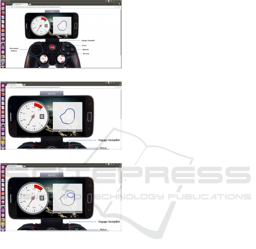
Figure 4: No attack.
Figure 5: First attack.
Figure 6: Second attack.
effects of security attacks in cyber-physical systems
using a co-simulation framework. More complex at-
tacks than those shown in the paper can be modeled.
In particular, models of attacks could be extended to
timed automata (Alur and Dill, 1994), using the trans-
lation from networks of timed automata to PVS the-
ories defined in (Bernardeschi et al., 2018). Moreo-
ver, verification is not addressed in this paper. Follo-
wing an approach similar to that in (Fitzgerald et al.,
2007), where it has been formally proved that, in case
of automatic control, the path followed by the robot
corresponds to the line on the ground, properties of
the system under attack that are satisfied for all co-
simulation runs could be analyzed. This will be ob-
jective of further work.
ACKNOWLEDGEMENTS
Work partially supported by the Italian Ministry of
Education and Research (MIUR) in the framework
of the CrossLab project (Departments of Excellence).
The authors also thank the INTO-CPS project for pro-
viding the case study and the co-simulation environ-
ment.
REFERENCES
Alur, R. and Dill, D. L. (1994). A theory of timed automata.
Theoretical Computer Science, 126(2):183–235.
Avvenuti, M., Bernardeschi, C., Francesco, N. D., and
Masci, P. (2012). JCSI: A tool for checking secure
information flow in java card applications. Journal of
Systems and Software, 85(11):2479–2493.
Bagnato, A., Brosse, E., Quadri, I., and Sadovykh, A.
(2015). INTO-CPS: An integrated “tool chain” for
comprehensive model-based design of cyber-physical
systems. This publication is part of the Horizon 2020
project: Integrated Tool chain for model-based design
of CPSs (INTO-CPS), project/GA number 644047.
Bernardeschi, C., Cassano, L., Domenici, A., and Sterpone,
L. (2014). ASSESS: A simulator of soft errors in the
configuration memory of SRAM-Based FPGAs. IEEE
Trans. on CAD of Integrated Circuits and Systems,
33(9):1342–1355.
Bernardeschi, C. and Domenici, A. (2016). Verifying safety
properties of a nonlinear control by interactive theo-
rem proving with the Prototype Verification System.
Inf. Process. Lett., 116(6):409–415.
Bernardeschi, C., Domenici, A., and Masci, P. (2018).
A PVS-Simulink Integrated Environment for Model-
Based Analysis of Cyber-Physical Systems. IEEE
Trans. Software Eng., 44(6):512–533.
Blochwitz, T., Otter, M., Akesson, J., Arnold, M., Clauß,
C., Elmqvist, H., Friedrich, M., Junghanns, A.,
Mauss, J., Neumerkel, D., Olsson, H., and Viel, A.
(2012). Functional Mockup Interface 2.0: The Stan-
dard for Tool independent Exchange of Simulation
Models. In Proceedings of the 9th International MO-
DELICA Conference; September 3-5; 2012; Munich;
Germany, number 76 in Link
¨
oping Electronic Con-
ference Proceedings, pages 173–184. Link
¨
oping Uni-
versity Electronic Press.
Broenink, J. F. (1999). 20-SIM software for hierarchi-
cal bond-graph/block-diagram models. Simulation
Practice and Theory, 7(5):481–492.
Burmester, M., Magkos, E., and Chrissikopoulos, V. (2012).
Modeling security in cyberphysical systems. Inter-
national Journal of Critical Infrastructure Protection,
5(3):118 – 126.
Butler, M., Jones, C., Romanovsky, A., and Troubitsyna, E.,
editors (2009). Methods, Models and Tools for Fault
Tolerance. Springer-Verlag, Berlin, Heidelberg.
Modeling and Simulation of Attacks on Cyber-physical Systems
707

Dutertre, B. (1996). Elements of mathematical analysis in
pvs. In Proceedings of the 9th International Con-
ference on Theorem Proving in Higher Order Lo-
gics, TPHOLs ’96, pages 141–156, Berlin, Heidel-
berg. Springer-Verlag.
Ferrante, A., Kaitovic, I., and Milosevic, J. (2014). Mo-
delling requirements for security-enhanced design of
embedded systems.
Fitzgerald, J. S., Larsen, P. G., and Verhoef, M. (2007).
Vienna Development Method. John Wiley & Sons, Inc.
Humayed, A., Lin, J., Li, F., and Luo, B. (2017). Cyber-
Physical Systems Security—A Survey. IEEE Internet
of Things Journal, 4(6):1802–1831.
Lanotte, R., Merro, M., and Tini, S. (2018). Towards a for-
mal notion of impact metric for cyber-physical attacks
(full version). CoRR, abs/1806.10463.
Larsen, P. G., Battle, N., Ferreira, M., Fitzgerald, J., Laus-
dahl, K., and Verhoef, M. (2010). The Overture Ini-
tiative Integrating Tools for VDM. SIGSOFT Softw.
Eng. Notes, 35(1):1–6.
Larsen, P. G., Fitzgerald, J., Woodcock, J., Fritzson, P.,
Brauer, J., Kleijn, C., Lecomte, T., Pfeil, M., Green,
O., Basagiannis, S., and Sadovykh, A. (2016). Inte-
grated tool chain for model-based design of Cyber-
Physical Systems: The INTO-CPS project. In 2016
2nd International Workshop on Modelling, Analysis,
and Control of Complex CPS (CPS Data), pages 1–6.
Masci, P., Zhang, Y., Jones, P. L., Oladimeji, P., D’Urso,
E., Bernardeschi, C., Curzon, P., and Thimbleby, H.
(2014). Combining PVSio with Stateflow. In NASA
Formal Methods - 6th International Symposium, NFM
2014, Houston, TX, USA, April 29 - May 1, 2014. Pro-
ceedings, pages 209–214.
Mauro, G., Thimbleby, H., Domenici, A., and Bernardes-
chi, C. (2017). Extending a user interface prototyping
tool with automatic MISRA C code generation. In Du-
bois, C., Masci, P., and M
´
ery, D., editors, Proceedings
of the Third Workshop on Formal Integrated Develop-
ment Environment, Limassol, Cyprus, November 8,
2016, volume 240 of Electronic Proceedings in Theo-
retical Computer Science, pages 53–66. Open Publis-
hing Association.
Meadows, C. (2003). Formal methods for crypto-
graphic protocol analysis: emerging issues and trends.
IEEE Journal on Selected Areas in Communications,
21(1):44–54.
modelio (2018). Modelio web site.
http://www.modelio.org retrieved 11/29/2018.
Mu
˜
noz, C. (2003). Rapid prototyping in PVS. Technical
Report NIA 2003-03, NASA/CR-2003-212418, Nati-
onal Institute of Aerospace, Hampton, VA, USA.
Oladimeji, P., Masci, P., Curzon, P., and Thimbleby, H.
(2013). PVSio-web: a tool for rapid prototyping de-
vice user interfaces in PVS. In FMIS2013, 5th Inter-
national Workshop on Formal Methods for Interactive
Systems, London, UK, June 24, 2013.
Owre, S., Rushby, J., and Shankar, N. (1992). PVS: A pro-
totype verification system. In Kapur, D., editor, Auto-
mated Deduction — CADE-11, volume 607 of Lecture
Notes in Computer Science, pages 748–752. Springer
Berlin Heidelberg.
Palmieri, M., Bernardeschi, C., and Masci, P. (2017). Co-
simulation of semi-autonomous systems: The line fol-
lower robot case study. In Software Engineering and
Formal Methods — SEFM 2017 Collocated Works-
hops: DataMod, FAACS, MSE, CoSim-CPS, and FO-
CLASA, Trento, Italy, September 4-5, 2017, Revised
Selected Papers, pages 423–437.
ForSE 2019 - 3rd International Workshop on FORmal methods for Security Engineering
708
