
Evaluation of Embedded Camera Systems for Autonomous Wheelchairs
Cristian Vilar, Benny Th
¨
ornberg and Silvia Krug
Department of Electronics Design, Mid Sweden University, Holmgatan, Sundsvall, Sweden
Keywords:
Autonomous Wheelchair, Embedded Camera System, Time-of-Flight, Stereo Camera, RANSAC.
Abstract:
Autonomously driving Power Wheelchairs (PWCs) are valuable tools to enhance the life quality of their users.
In order to enable truly autonomous PWCs, camera systems are essential. Image processing enables the
development of applications for both autonomous driving and obstacle avoidance. This paper explores the
challenges that arise when selecting a suitable embedded camera system for these applications. Our analysis
is based on a comparison of two well-known camera principles, Stereo-Cameras (STCs) and Time-of-Flight
(ToF) cameras, using the standard deviation of the ground plane at various lighting conditions as a key quality
measure. In addition, we also consider other metrics related to both the image processing task and the embed-
ded system constraints. We believe that this assessment is valuable when choosing between using STC or ToF
cameras for PWCs.
1 INTRODUCTION
Power Wheelchairs (PWCs) have improved the qual-
ity of life for their users by giving them more indepen-
dence and transportation facilities. The next step in
PWC development is to add features like autonomous
driving and obstacle avoidance in order to continue
improving the system usability. Caregiver detection
and tracking is a step towards the development of a
fully autonomous PWC. The caregiver’s position can
be used as a reference to steer a PWC in a side-by-
side configuration where the wheelchair follows the
caregiver autonomously.
To achieve this, such autonomous driving applica-
tions need to collect and store information regarding
the PWC’s environment using sensors, image cam-
eras, and electronic systems. The required steps in-
clude the detection of the surrounding objects, mea-
suring their relative distances and their recognition.
These steps have to be executed with high accuracy
and precision in order to ensure robust autonomous
driving. Camera systems are essential for this, and
are already applied to various automotive use cases.
Autonomous driving PWCs and other mobile
robots require the ability to detect, measure and rec-
ognize objects at relatively short distances in compar-
ison with automotive applications. Visual cameras
can detect obstacles but not measure distances with
enough accuracy at short ranges. 3D LiDAR cam-
eras, by contrast, can measure long range distances
accurately, but usually do not have a detailed enough
resolution to recognize objects (Park et al., 2018).
Moreover, these cameras are difficult to embed into
the PWC frame due to size and weight limitations.
Depth cameras, such as Stereo-Cameras (STCs) or
Time-of-Flight (ToF) cameras, are yet another option.
They can detect objects, measure distances and pro-
vide detailed information about the objects. In addi-
tion, they combine depth measurements with visual
images to provide additional information useful for
object recognition. STCs and ToF cameras are based
on different measuring principles and we expect them
to have a different performance and impact on the ob-
ject recognition. In this paper, we intend to investigate
these differences with respect to the camera suitability
for an autonomously driving PWC.
This investigation is focused on the quality of
depth data required for the segmentation of objects
above a Ground Plane (GP) at short range distances.
The main goal is to evaluate the challenges of STC
and ToF camera technologies for autonomous PWC
applications and, by extension, for robotics and au-
tomated guided vehicles. The paper studies a real-
world camera application using depth cameras non-
specifically designed for research that are however
available as of the shelf hardware and could meet the
embedded system constraints. The scientific contribu-
tion of this paper is a qualitative comparison of point
cloud data measured by a ToF camera and an STC. To
achieve this, we discuss multiple metrics with respect
76
Vilar, C., Thörnberg, B. and Krug, S.
Evaluation of Embedded Camera Systems for Autonomous Wheelchairs.
DOI: 10.5220/0007678700760085
In Proceedings of the 5th International Conference on Vehicle Technology and Intelligent Transport Systems (VEHITS 2019), pages 76-85
ISBN: 978-989-758-374-2
Copyright
c
2019 by SCITEPRESS – Science and Technology Publications, Lda. All rights reserved

to the constraints introduced by the embedded PWC.
Due to the focus on available hardware, our goal is
however not to compare the latest algorithms for dif-
ferent subtasks of the depth data processing.
The paper is organized as follows. First, we intro-
duce the fundamentals of depth camera technologies
and review other works targeting autonomous PWCs
in Section 2. In Section 3, we present the criteria for
the camera selection, the camera setup, the required
data processing steps as well as the experiment defi-
nition. In Section 4, we present and analyze the mea-
surement results. Our results are qualitatively dis-
cussed in relation to the experimental goals and the
PWC constrains for the selection of a depth camera
for autonomous PWC applications in Section 5. Fi-
nally, we conclude the paper in Section 6.
2 FUNDAMENTALS AND
RELATED WORK
2.1 Camera Operation Principles
ToF cameras measure the time of flight of the re-
flected light at each point in the image. They use
an Infra-Red (IR) active lighting source to illuminate
the scene. There are two modes of operation: pulsed
lighting or Continuous Wave Modulation (CWM). In
pulsed lighting mode, the camera measures the time-
of-flight of a very short pulse interval directly. This
method has the inherent difficulty of generating and
measuring short pulses in order to achieve centime-
ter resolution in the range image. CWM means in-
tensity modulated light at a given frequency ( f
m
). It
then measures the phase shift (∆Φ) between the emit-
ted and reflected light in order to determine the depth
(d
ToF
):
d
ToF
=
c
4π f
m
(1)
The most common CMW approach is the Lock-in-
Pixel architecture (Ringbeck and Hagebeuker, 2007).
This approach samples the emitted light in four differ-
ent phases [0
◦
;90
◦
;180
◦
;270
◦
]. CWM, compared to
pulsed operation, reduces the pixel size and thus en-
ables increased image resolution. Typically, the max-
imum spatial resolution is approximately 320×240
pixels and thus significantly lower than for a 2D cam-
era.
The depth resolution depends mainly of techno-
logical parameters, in this case, the IR light modu-
lation frequency ( f
m
) (McClure et al., 2010) and er-
rors like wiggling or amplitude related errors (Huss-
mann et al., 2014). The maximum phase shift limits
the depth range ambiguity distance (d
MAX
):
d
MAX
=
1
2(c/ f
m
)
(2)
In addition, ToF sensors suffer from low sensitiv-
ity and as a consequence high noise levels (Langmann
et al., 2012). Ambient sunlight can interfere with the
active illumination, mainly due to the limited dynamic
range of the pixels. However, active IR lighting al-
lows nightlight operation and reduces the depth com-
puting costs in comparison with STCs.
In contrast to ToF cameras, Stereo Cameras are
passive and do not require active illumination under
daylight conditions. STCs are based on two single
cameras placed side-by-side measuring the depth us-
ing principles of triangulation (Gonzalez and Woods,
2010). In STCs, the depth is determined by com-
puting the pixel disparity (D) between both camera
images (Kyt
¨
o et al., 2011) by a block-matching al-
gorithm. Hence, it is a software-based solution and
therefore it demands more computing resources and
time.
This technology also requires a previous camera
calibration in order to compute the pixel disparity
properly. Depth d
STC
and depth resolution ∆d
STC
are
calculated as follows
d
STC
=
f B
D
(3)
∆d
STC
=
d
2
STC
∆D
f B
(4)
defined by the baseline (distance between cameras)
(B), focal length ( f ), and precision of disparity com-
putation (∆D).
The spatial image resolution is limited only by the
camera sensor and thus significantly higher than for
ToF cameras. An STC is normally not able to operate
in nightlight or low-light conditions. It is, however,
possible to use active illumination to solve this limi-
tation.
2.2 Literature Review
In (Kobayashi et al., 2012), the authors explore the
idea of autonomous PWC steering, using the care-
giver position as driving reference. This facilitates a
reduction of workload for the caregiver and makes a
more natural communication between caregiver and
the wheelchair user possible. The caregiver is de-
tected and recognized by a rotating LiDAR and an
omnidirectional camera placed on a mast. The inte-
gration of these bulky system components into a PWC
frame is, however, impossible due to the required size.
Evaluation of Embedded Camera Systems for Autonomous Wheelchairs
77

In (Wu et al., 2013), the authors use a ToF kinect
camera placed on a mast to detect and track the care-
giver walking next to the PWC. Kinect’s combination
of depth measurements and visual images provides
enough information required for caregiver recognition
as well as autonomous navigation of a PWC. How-
ever, the high camera placement on a mast prevents
the detection of obstacles on the ground, which is re-
quired for a safe operation of the PWC. Such a mast
modifies the ergonomics, structure and appearance of
the PWC in a way not suitable for a commercial prod-
uct.
A better camera placement for ergonomics and
safety is the armrest of the PWC. In (Motokucho and
Oda, 2014), an STC is placed into the PWC’s arm-
rest without disturbing the PWC’s manual operation.
The lower camera position reduces the scene Field of
View (FOV), which decreases the detection probabil-
ity of complete human shapes. Thus, the position of
the caregiver is determined by the recognition of his
or her legs.
Another approach is presented in (Udsatid et al.,
2012): the caregiver is recognized by measuring the
position of the feet above the GP. In this case, the
camera is tilted down, looking for objects above the
GP. The detected objects are segmented based on a
height threshold above the GP. Thresholding-based
segmentation is limited by the depth camera resolu-
tion at different distances and also by the camera ro-
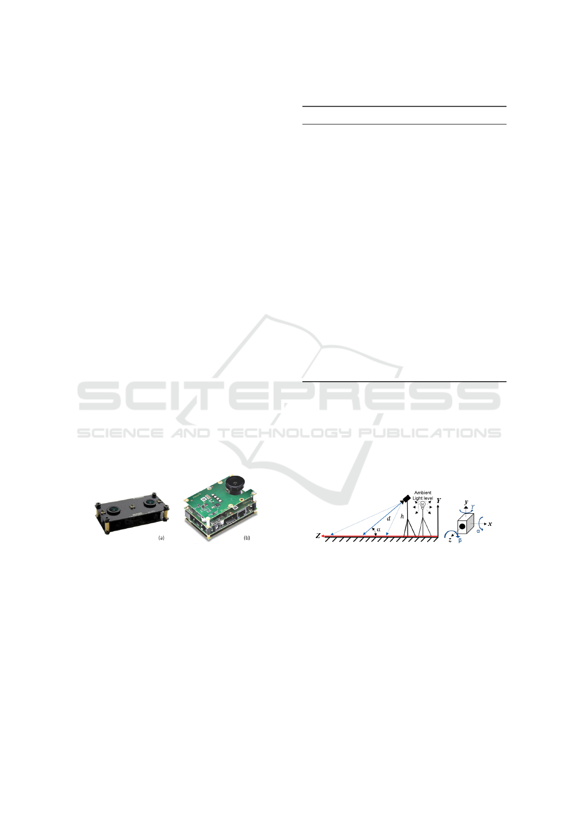
tation (α,β,γ) with respect the GP, cf. Figure 2. Due
to the movements of the PWC, the camera angles are
not constant with respect to the GP. Hence, height-
thresholding is not a valid method for GP segmenta-
tion in autonomous PWCs and other mobile robotics
applications.
In addition to these works targeting the camera
system for PWCs, several other studies on robotics
and camera technology analyze the ToF and STC per-
formance and calibration methods using flat surfaces
or distributed objects as target references, e.g. (Lang-
mann et al., 2012; He et al., 2017; Francis et al.,
2015; Kyt
¨
o et al., 2011; Sun et al., 2018; Kim et al.,
2005). Using this methods, a depth camera collects
point cloud data at different depths in order to mea-
sure accuracy. In our study, we instead use a tilted flat
GP as a reference because it is a more representative
and realistic experimental setup. The tilted GP allows
us to analyze the quality of the measured point cloud
data at various distances in a single depth image.
Few other camera comparisons between ToF cam-
eras and STCs exist that compare the technologies e.g.
in (Kazmi et al., 2014; Beder et al., 2007). These do
however not focus on the dependency on the illumi-
nation level, the distance range, the object’s reflec-
tivity, and camera power consumption. We consider
relevant to analyze the effect of these variables in or-
der to choose a suitable camera in accordance with
the application requirements presented in Section 3.1.
Therefore, we perform our experiment using different
levels of ambient light and different levels of active
illumination as well as different object textures. More
recent comparisons with a focus on the quality of the
depth data are not available to the best of our knowl-
edge.
3 METHOD
3.1 PWC Application Requirements
Our goal in this paper is to evaluate, which camera
technology provides the best performance to enable
robust detection of a caregiver. In order to develop
such a PWC, a set of constrains regarding the cam-
era specifications and requirements has to be fulfilled,
which we will briefly introduce here.
Reliable object detection and recognition is a cen-
tral requirement of the system. Here, we target the
detection of a caregiver by recognizing the caregiver’s
feet. The following general constraints apply:
Operation Environment, an autonomous PWC has
to operate in indoor and outdoor environments
and be able to reliably detect the feet of the care-
giver under all circumstances.
Object Texture, the camera has to detect objects
with different textures and light reflective indexes.
Effective Range, the camera has to measure dis-
tances to objects in the range 0–2.5 m from the
PWC.
Minimum Height of a Detectable Objects, the
camera has be able to detect small objects above
the ground plane in order to detect the feet of
the caregiver. Therefore, the GP depth variation
should be below 3 cm.
Illumination Conditions, the camera has to be able
to operate in both daylight and nightlight condi-
tions. This is required for PWC usability.
Real-time Operation, image capture and depth
computation must run in real-time and at a
throughput of no less than 10 images per second.
Size and Weight, the camera size and weight are
constrained in order to avoid modifying the
PWC’s dynamic performance. Small camera
packages are preferred.
VEHITS 2019 - 5th International Conference on Vehicle Technology and Intelligent Transport Systems
78
Camera Placement, the camera has to be fully em-
bedded into the PWC frame in order to improve
the overall system safety and ergonomics. The
preferred camera placement is the PWC’s armrest.
Power Consumption, low power consumption is
crucial for the operating range of a battery PWC.
Heat dissipation can make the mechanical integra-
tion of a camera difficult.
Usually, GP detection and removal is the first pro-
cessing step for autonomous robot navigation systems
(Choi et al., 2014; Zeineldin and El-Fishawy, 2016).
Once the GP is removed from the 3D data, it becomes
easier to find the objects above it. The minimum size
and height of the detectable objects depend mainly on
the standard deviation of the GP data. Hence, small
objects are more difficult to segment from a noisy GP.
The most used method for GP subtraction on
depth images is the Random Sampled Consensus al-
gorithm (RANSAC). It allows fitting planar surfaces
from arbitrary 3D point cloud scenes. This method re-
lies on the GP flatness measurement and therefore de-
pends on the camera depth resolution and calibration.
We focus on GP data quality in this paper, because
of the fundamental link between object segmentation
and GP depth variation.
3.2 Camera Selection
We have selected a Duo3D MLX (cf. Figure 1a) as the
STC and Melexis EVK75123 (cf. Figure 1b) as the
ToF camera. The main camera parameters are shown
in Table 1.
Figure 1: Selected cameras for experimental evaluation (a)
Duo3D MLX (b) Melexis EVK75123.
Both cameras include active illumination and are
thus suitable for both daytime and nightlight opera-
tion. The cameras can operate in a calibrated point
cloud mode and automatically suppress distortions
caused by the respective lens. This is important to re-
duce the calibration and computation effort. The pixel
resolution of the two cameras differ, mostly due to the
size limitations of the ToF technology.
The pixel disparity for the STC is computed by
an auxiliary computer using the application program-
ming interface provided by the camera manufacturer.
Table 1: Camera specifications.
Parameter Camera
Model Duo3D MLX EVK75123
Technology STC ToF CWM
Frame
640×480 pixels 320×240 pixels
Resolution
Max Frame Rate 98 fps 60 fps
Pixel Size 6×6 µm 15×15 µm
FOV 170
◦
110
◦
Baseline 30 mm –
Light
– 12–48 MHz
Modulation
Focal Length 2.1 mm 2.8 mm
IR Lighting
3.4 W 0–25 W
Power
Power
2 W 11 W
Consumption
IR Wavelength
850 nm 850 nm
LED VCSEL
IR Blocking
no yes
Filter
Size 52×25×13 mm 80×50×35 mm
For the ToF, instead, depth computation is perform di-
rectly on the camera.
3.3 Camera Setup
Both cameras are placed side-by-side on a tripod at
the same height (h), tilted down 30 degrees (α) mea-
suring a flat GP as shown in Figure 2.
Figure 2: Camera setup and camera angle definition.
This camera configuration reproduces a camera
placement on the PWC’s armrest looking for the care-
giver’s legs and obstacles above the GP.
3.4 Depth Data Processing and
Measurement Procedure
We execute a number of pre-processing steps prior to
the actual experiments. These initial depth processing
steps are shown in Figure 3 and executed separately
on data from both cameras.
Evaluation of Embedded Camera Systems for Autonomous Wheelchairs
79
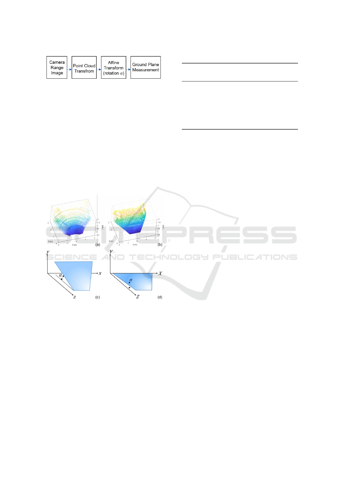
Figure 3: Processing steps for depth data analysis.
First, the range images are transformed into a 3D
Point Cloud representation. Example results from this
transformation are shown in Figure 4a and Figure 4b.
The point cloud data are then rotated using an affine
geometrical transformation according to the camera
angle (α), see Figure 4c. This rotation aligns the mea-
sured GP with the camera coordinate system, see Fig-
ure 4d. Measured GP data show geometrical distor-
tion and statistical variation due to the camera depth
resolution, noise and camera calibration errors. We
limited our data analysis into a slide on the X-axis
along the Z and Y axes rather that considering all GP
data. This allows us to discard the distortion due to
the calibration errors and keep only the depth noise
into the analysis.
Figure 4: (a) Point cloud data of the ToF camera. (b) Point
cloud data of the STC. (c) Original point cloud data rep-
resentation with respect the ground plane coordinates. (d)
Rotation of original point cloud data in order to align it with
the Z-Y axes.
ToF raw data is expected to be severely noisy and
requires data post-processing (Lenzen et al., 2013).
We have used two de-noising methods. Both are im-
plemented directly in the ToF camera. The first is a
edge-preserving bilateral filter. It smooths the depth
surfaces without distorting the image edges (Tomasi
and Manduchi, 1998; Paris et al., 2009). The second
method uses an intensity thresholding filter to resolve
the unwrapped depth pixels according to their corre-
sponding intensity values (McClure et al., 2010; Cho
et al., 2014).
Table 2: Camera parameters used for experiments.
Parameter Camera
STC ToF
Ambient light Dark 120 lx 2400 lx ∗
Gain 1 % 1 % 1 % –
Exposure (ms) 90 90 40 -
Integration (ms) - - - 0.6
IR Power (W) 3.4 3.4 0 25
Frame Rate (fps) 4 4 4 6
3.5 Performed Experiments
According to the PWC application requirements de-
fined in Section 3.1, and the camera setup in Sec-
tion 3.3, we defined the following experiments with
the aim to validate both camera technologies:
• Experiment 1 – Depth variation
• Experiment 2 – Impact of texture
• Experiment 3 – Effect of light absorbent materials
In Experiment 1, we measure the statistical vari-
ation of GP data under different ambient light con-
ditions using different active illumination intensities
and modulation frequencies. Camera parameters and
scene conditions are summarized in Table 2. Note that
there are experiments at three different levels of am-
bient light intensities for both cameras. The camera
settings for the ToF camera were made independent
of the ambient light, whereas the STC needed differ-
ent settings. Initially, we used a CWM frequency of
20 MHz for the ToF camera and an intensity thresh-
olding filter. To evaluate its impact, we repeated the
experiment without applying any filtering on the data
prior to analysis. To evaluate the impact of the CWM
setting, we performed additional measurements with
CWM frequencies of 12, 20, and 32 MHz, respec-
tively. We perform our comparison under static condi-
tions in order to gain a fundamental understanding of
the interplay between different parameters first. Due
to this, the STC frame rate and ToF integration time
have been configured at the same value in all the ex-
periments. The configuration is below the 10 fps we
defined for the real-time constraint. However, this is
not crucial for the static analysis and future analyses
of dynamic cases are planned.
Experiments 2 and 3 analyzed the effect of having
non-textured objects and light absorbent materials in
the scene. In Experiment 2 we estimated the impact
of textured surfaces to the GP measurement while we
added reflective and light-absorbent materials into the
scene of Experiment 3.
VEHITS 2019 - 5th International Conference on Vehicle Technology and Intelligent Transport Systems
80
These experiments provide us with valuable in-
sights into the GP variation under controlled condi-
tions. In addition, we studied the impact of different
camera configurations and operating principles on the
quality of the ground plane data and thus the possi-
bility of GP removal from the scene for later object
recognition. This is essential in order to select and im-
plement a corresponding camera system into a PWC
at a later point in time.
4 RESULTS AND ANALYSIS
4.1 Depth Variation Measurements
In Experiment 1, we analyzed the GP depth variation
by computing the standard deviation (σ) of the mea-
sured height along the GP Y-axis as is shown in Fig-
ure 2 at different ambient illumination conditions. We
believe this is a good metric to determine the mini-
mum detectable height of objects located above the
GP with respect to the measured distance. Results for
the STC are shown in Figure 5, and for the ToF cam-
era in Figure 6.
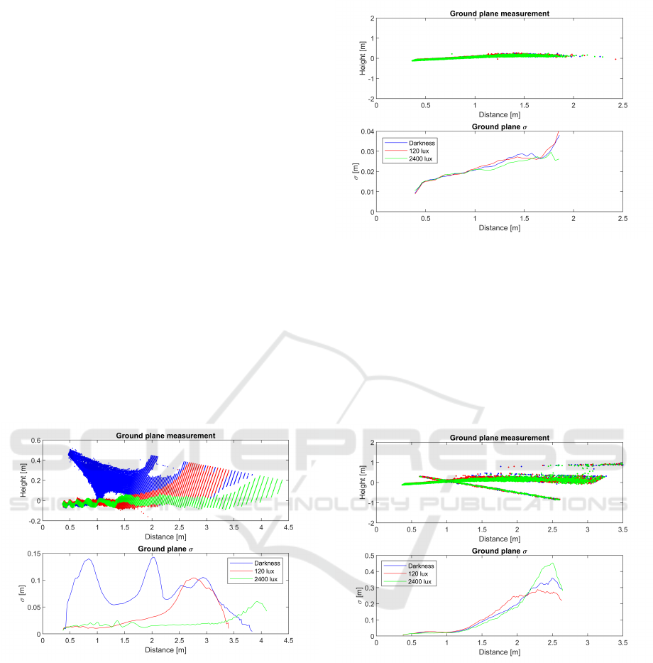
Figure 5: STC GP measurement of the Y-axis (height) and σ
along the Z-axis (depth) under different ambient light con-
ditions.
The upper graphs in Figures 5 to 9 show point
cloud data after rotation with α, as illustrated in Fig-
ure 4. Ideally, we should see a thin, straight line, per-
fectly aligned with the horizontal axis at zero level.
However, real-world measurements show limitations
from e.g. camera calibration and noise.
The results from the ToF camera shown in Fig-
ure 6 are invariant to the ambient light intensity. By
contrast, the STC results greatly depend on the am-
bient light intensity. In dark conditions, when only
STC active illumination is used, the measurement is
Figure 6: ToF GP measurement of the Y-axis (height) and σ
along the Z-axis (depth) under different ambient light con-
ditions with intensity thresholding filter.
very noisy, even at short distances. When the ambi-
ent light intensity increases, the GP depth variation
is reduced and the maximum measurement range in-
creases accordingly.
The same analysis was performed without inten-
sity thresholding filter for the ToF camera. Figure 7
shows the results. In this case, pixels with low intensi-
Figure 7: ToF GP measurement of the Y-axis (height) and σ
along the Z-axis (depth) under different ambient light con-
ditions without intensity thresholding filter.
ties are not removed and thus cause a depth measure-
ment error. Figures 6 and 7 both show that the dis-
tance of the ToF measurements is limited. Although
the used modulation frequency of 20MHz provides a
d
MAX
of 7.5 m according to Equation 2, the practical
measurement range is shorter in both cases. When
using the intensity thresholding filter it becomes even
less than 2 m, see Figure 6. The reason for this shorter
distance is the limited intensity of the reflected light.
The filter removes depth pixels whose intensity values
are lower than a specified threshold. This threshold
Evaluation of Embedded Camera Systems for Autonomous Wheelchairs
81
is based on low intensity levels being an indication
of low confidence in the phase measurements. Thus,
pixels above approximately 2.5 m do not have enough
intensity levels and are therefore deleted.
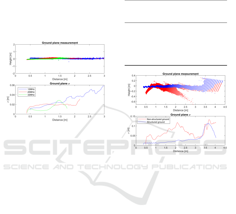
Finally, we assessed the impact of different CWM
frequencies of the ToF camera. As shown in Figure 8,
the maximum range and the GP depth variation are
reduced with an increasing CWM frequency.
Figure 8: ToF GP measurement using different different
CWM frequencies.
The σ of the ToF depth data increases for greater
distances in both camera measurements, but is more
severe for the STC. This result was expected due
to the STC depth resolution definition according to
Equation 4, which decreases quadratically with dis-
tance d
STC
. Thus, the non-linear behavior of ∆d
STC
in
practice limits the maximum distance d
STC
in which
objects can be detected above the GP.
The standard deviation of the ToF depth data is
increasing linearly according to the distance (cf. Fig-
ure 6. This linear behavior matches that of other ToF
cameras analyzed in (Shi et al., 2011). The maximum
range is mainly limited by the unwrapped depth pix-
els, caused by non-detectable phase shifts greater than
360 degrees. If they are not removed by e.g. an in-
tensity thresholding filter, then the GP variation will
increase (cf. Figure 7). Standard deviation measure-
ments for both cameras are summarized in Table 3.
4.2 Impact of Texture
In Experiment 2, we measured a GP with and without
a textured pattern in order to test the lack of a texture
in the STC’s block-matching algorithm. The results
are shown in Figure 9.
To perform the experiment, a non-textured flat
white surface with a length of 2.5 m was placed di-
Table 3: Standard deviation measurements for both cam-
eras.
GP Z [m] σ [mm]
STC ToF
12 MHz 20 MHz 32 MHz
0.5 12.7 13.3 12.3 8
1 10.5 17.1 19.8 6.4
1.5 20.3 25.6 19.6 27.2
2 31.5 32.7 16.4 –
2.5 75.6 41.7 – –
3 84.1 56.4 – –
Figure 9: STC GP measurement with textured and non-
textured GP surface.
rectly on top of the GP at a distance of 0.5 to 3 m from
the camera, along the GP. Both results are measured
in the same ambient light intensity, active IR illumi-
nation, and camera configuration.
The measurements of a non-textured GP show the
effect of an erroneous result from the disparity com-
putation due to difficulties matching 8×8 pixel blocks
without unique texture. As a result, the non-textured
GP becomes noisy, making it difficult to detect small
objects.
4.3 Effect of Light Absorbent Materials
In Experiment 3, we measured the effect of adding
light absorbent and light reflective patches on the GP
surface. The patches are 25 cm long and placed at
a distance of 0.6–0.85 m from the camera, along the
GP. Qualitative results for the STC are shown in Fig-
ure 10, and for the ToF camera in Figure 11.
The light absorbing material has no major impact
on the depth measurements of the GP by the STC. It
is important to note that for both cases σ
STC
of the
depth data increases due to the patch edges and not
VEHITS 2019 - 5th International Conference on Vehicle Technology and Intelligent Transport Systems
82
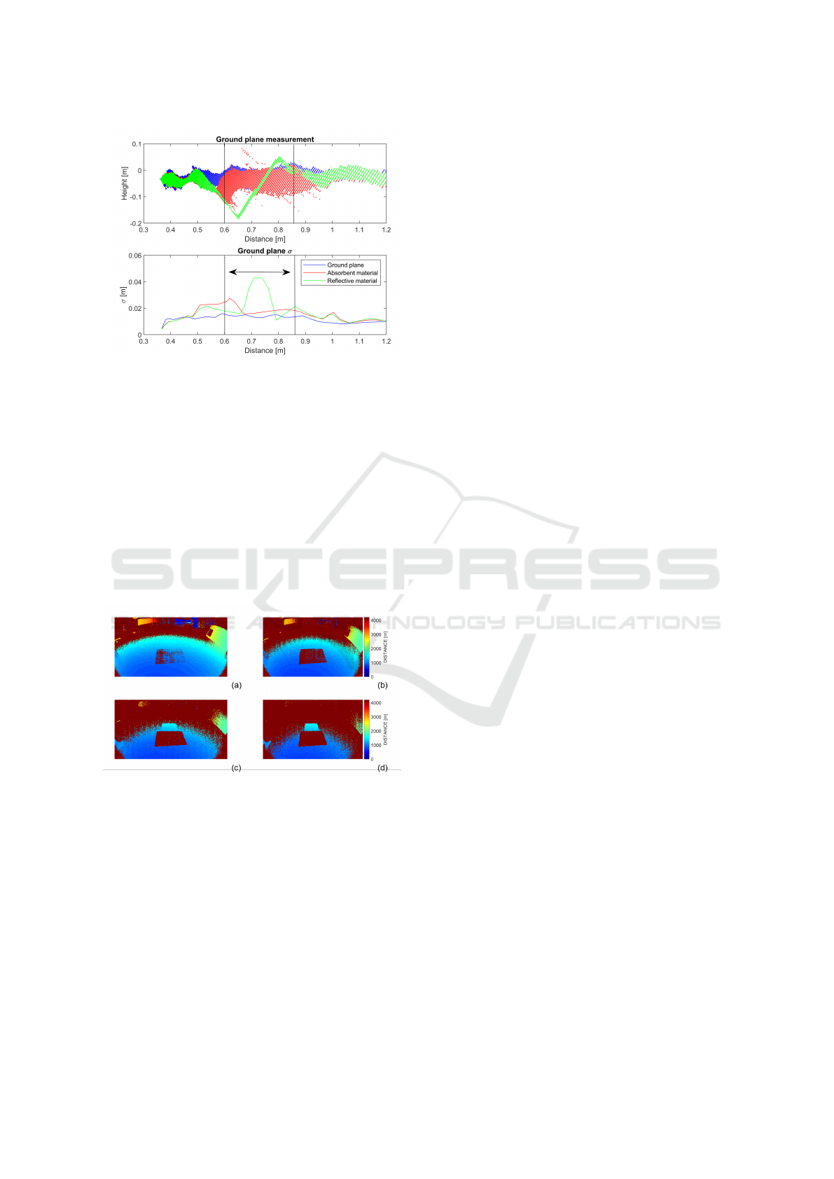
Figure 10: STC GP measurement with light absorbent and
light reflective material patches.
because of the light absorbing material itself. When a
highly reflective material patch is used, the GP level
changes significantly and causes a depth inaccuracy
in the measurement.
The effect of the IR light reflection for the ToF
has been measured in Figure 11. Here, the cam-
era operates at a CWM frequency of 32 MHz. Both
patches are placed in each scene corresponding to a
sub-figure. The light absorbing patch is shown as
the dark rectangular shape at the bottom of each sub-
figure, while the light reflector is shown above it (e.g.
the bright blue rectangular shape in Figure 11d).
Figure 11: ToF range image data at different relative ac-
tive illumination powers: (a) 100 %, (b) 50 %, (c) 25 %, (d)
10 %.
At 100 % power, the light absorbing patch reduces
the intensity of the reflected light and the patch be-
comes difficult to detect. When the active illumina-
tion power is decreased, the absorbing patch becomes
undetectable, while the reflective patch is still per-
fectly detectable, even at low illumination powers.
5 DISCUSSION
Our measurements show that in general σ increases
with the distance and that a maximum distance of
around 2.5 m can be achieved with both cameras.
Both cameras chosen for our study show similar σ of
the GP under daylight conditions and up to a distance
of two meters. The σ of roughly 3 cm means that ob-
jects higher than 3 cm can be detected above the GP
with a confidence of 68 %. As such, both fulfill the
general requirements of target effective range, and the
minimum height of a detectable object as defined in
Section 3.1. However, we expect objects closer to the
cameras to be more accurately detected due to a lower
σ of the GP for these measurements.
For the STC, the parameters ∆d
STC
, d
STC
and
σ
STC
are improved when the STC is working in op-
timal ambient light conditions. We believe that this
effect is caused by an improved signal-to-noise-ratio
(SNR) at stronger illumination levels. Lower SNR de-
grades the performance of the block-matching dispar-
ity algorithm and thus ∆D increases as reported by
(Sabater et al., 2011). In addition, dark illumination
levels require higher exposure times, limiting then the
maximum frame rate. In a PWC application, this ef-
fect has to be considered when ensuring real-time op-
eration and dynamic movement. In practise, camera
images can be blurred if objects in the scene or the
PWC are moving. Especially, lower illumination con-
ditions are expected to be critical due to the higher ex-
posure time. Blurring will, as a consequence, degrade
the block-matching algorithm performance.
For the ToF cameras, the maximum range depends
mainly on the CWM frequency (Hussmann et al.,
2014; Dashpute et al., 2018). It decreases with higher
modulation frequencies. In practical applications, in-
creasing the CWM frequency triggers phase shift er-
rors, causing higher depth variation towards the end
of the observed range. This problem can be solved
by limiting the scene objects within an experimentally
obtained maximum distance.
Even if all the scene objects are inside this safe
distance range, we can detect unwrapped depth pix-
els as shown in Figure 7 for the ToF camera. These
pixels can be removed by an intensity thresholding
filter, but the useful distance range will be further re-
duced as a consequence. This problem can be mit-
igated partially by increasing the active illumination
power. However, using active illumination requires
a higher power consumption that cannot be avoided
if an extended distance range is required. This is es-
pecially crucial as the ToF camera range was already
shorter compared to the STC and lower than the limit
defined in Section 3.1. As for STC, ToF dynamic per-
Evaluation of Embedded Camera Systems for Autonomous Wheelchairs
83

formance can also be limited due to moving objects
in the scene under low active illumination conditions.
Moving objects can require to reduce the integration
time in that case, but and as a consequence, the noise
level and σ will increase (Gay-Bellile et al., 2015),
limiting thus the maximum distance range.
The presence of light absorbent materials poses a
severe challenge for the ToF camera. Light absorbent
objects cannot be detected by this type of camera,
even at relatively short distances. This dependency on
the material’s reflectivity makes caregiver detection a
challenge when low reflective clothing are used. As a
countermeasure the active illumination power can be
increased at the cost of higher power consumption.
By contrast, STCs can detect light absorbent ob-
jects under ambient daylight conditions. However, re-
flective objects cause inaccurate depth measurements
by the STCs. This inaccuracy is most likely caused
by the lack of texture on the saturated reflective patch.
A similar behavior was observed for the non-textured
GP. Disparity computation errors occur due to the lack
of texture. If such errors originate from saturated re-
gions, the problem could probably be mitigated if a
high dynamic range imager were used. Where the
levels of GP texture are limited, increasing the size
of the pixel block used to compute pixel disparities
could help. We can expect this problem for indoor
scenarios, icy/wet conditions outdoors, or for clothing
with low levels of texture. However, GPs in outdoor
conditions normally provide good enough texture for
STCs.
Since STCs are able to operate in daylight con-
ditions without additional active illumination, a lot
of heat dissipation and power consumption can be
avoided. However, ToF cameras require active illu-
mination in all scenarios in order to maintain a high
level of SNR. As a consequence, ToF cameras have
much higher levels of heat dissipation that require a
careful thermal design. Embedding electronics into
the armrest of a PWC can be a challenge at higher
levels of heat dissipation. This is never the case when
STCs are used in daylight conditions.
6 CONCLUSIONS
In this paper, we reviewed challenges related to inte-
gration and the use of depth cameras on PWCs.
The main limitation of ToF cameras is the noise
level in combination with the active illumination
power. STCs, for their part, are limited by the level of
ambient illumination and by the texture of the objects
in order to successfully compute the pixel disparities.
Both STC and ToF camera technologies are suit-
able for e.g. obstacle or caregiver detection by the
PWC but we prefer STC because of the lower heat
dissipation and power savings in daylight conditions,
as well as the more robust detection of light absorbent
materials. The results from this study should be rele-
vant for any low-speed vehicle or autonomous robot.
As a future step, we plan to assess the dynamic
performance of both cameras under dynamic condi-
tions with moving objects in the scene. We believe
that the dynamic performances will be degraded un-
der low illumination levels and higher exposure or in-
tegration times.
REFERENCES
Beder, C., Bartczak, B., and Koch, R. (2007). A Compari-
son of PMD-Cameras and Stereo-Vision for the Task
of Surface Reconstruction using Patchlets. In Con-
ference on Computer Vision and Pattern Recognition
(CVPR), pages 1–8.
Cho, J., Choi, J., Kim, S.-J., Park, S., Shin, J., Kim, J. D.,
and Yoon, E. (2014). A 3-D Camera With Adaptable
Background Light Suppression Using Pixel-Binning
and Super-Resolution. IEEE Journal of Solid-State
Circuits, 49(10):2319–2332.
Choi, S., Park, J., Byun, J., and Yu, W. (2014). Robust
Ground Plane Detection from 3D Point Clouds. In
14th International Conference on Control, Automa-
tion and Systems (ICCAS), pages 1076–1081.
Dashpute, A., Anand, C., and Sarkar, M. (2018). Depth
Resolution Enhancement in Time-of-Flight Cameras
Using Polarization State of the Reflected Light. IEEE
Transactions on Instrumentation and Measurement,
PP(1):1–9.
Francis, S. L. X., Anavatti, S. G., Garratt, M., and Shim,
H. (2015). A ToF-Camera as a 3D Vision Sensor for
Autonomous Mobile Robotics. International Journal
of Advanced Robotic Systems, 12(11):156.
Gay-Bellile, V., Bartoli, A., Hamrouni, K., Sayd, P., Bour-
geois, S., and Belhedi, A. (2015). Noise modelling
in time-of-flight sensors with application to depth
noise removal and uncertainty estimation in three-
dimensional measurement. IET Computer Vision,
9(6):967–977.
Gonzalez, R. and Woods, R. (2010). Digital Image Process-
ing (Third Edition). Prentice-Hall Inc.
He, Y., Liang, B., Zou, Y., He, J., and Yang, J. (2017).
Depth Errors Analysis and Correction for Time-of-
Flight (ToF) Cameras. Sensors, 17(1):92.
Hussmann, S., Knoll, F., and Edeler, T. (2014). Modula-
tion method including noise model for minimizing the
wiggling error of tof cameras. IEEE Transactions on
Instrumentation and Measurement, 63(5):1127–1136.
Kazmi, W., Foix, S., Aleny
`
a, G., and Andersen, H. J.
(2014). Indoor and outdoor depth imaging of leaves
with time-of-flight and stereo vision sensors: Analy-
VEHITS 2019 - 5th International Conference on Vehicle Technology and Intelligent Transport Systems
84

sis and comparison. ISPRS Journal of Photogramme-
try and Remote Sensing, 88:128–146.
Kim, W. S., Ansar, A. I., Steele, R. D., and Steinke, R. C.
(2005). Performance Analysis and Validation of a
Stereo Vision System. In International Conference on
Systems, Man and Cybernetics, pages 1409–1416.
Kobayashi, Y., Suzuki, R., and Kuno, Y. (2012). Robotic
Wheelchair with Omni-directional Vision for Moving
alongside a Caregiver. In 38th Annual Conference on
IEEE Industrial Electronics Society (IECON), pages
4177–4182.
Kyt
¨
o, M., Nuutinen, M., and Oittinen, P. (2011). Method
for measuring stereo camera depth accuracy based on
stereoscopic vision. In Three-Dimensional Imaging,
Interaction, and Measurement.
Langmann, B., Hartmann, K., and Loffeld, O. (2012).
Depth Camera Technology Comparison and Perfor-
mance Evaluation. In 1st International Conference
on Pattern Recognition Applications and Methods
(ICPRAM), pages 438–444.
Lenzen, F., Kim, K. I., Sch
¨
afer, H., Nair, R., Meister, S.,
Becker, F., Garbe, C. S., and Theobalt, C. (2013). De-
noising strategies for time-of-flight data. In Time-of-
Flight and Depth Imaging. Sensors, Algorithms, and
Applications, pages 25–45. Springer.
McClure, S. H., Cree, M. J., Dorrington, A. A., and Payne,
A. D. (2010). Resolving depth-measurement ambigu-
ity with commercially available range imaging cam-
eras. In Image Processing: Machine Vision Applica-
tions III.
Motokucho, T. and Oda, N. (2014). Vision-based Human-
Following Control using Optical Flow Field for Power
Assisted Wheelchair. In 13th International Workshop
on Advanced Motion Control (AMC), pages 266–271.
Paris, S., Kornprobst, P., Tumblin, J., Durand, F., et al.
(2009). Bilateral Filtering: Theory and Applications.
Foundations and Trends
R
in Computer Graphics and
Vision, 4(1):1–73.
Park, K., Kim, S., and Sohn, K. (2018). High-Precision
Depth Estimation with the 3D LiDAR and Stereo Fu-
sion. In International Conference on Robotics and Au-
tomation (ICRA), pages 2156–2163.
Ringbeck, T. and Hagebeuker, B. (2007). A 3D time of
flight camera for object detection. In Optical 3-D
Measurement Techniques.
Sabater, N., Morel, J.-M., and Almansa, A. (2011). How
accurate can block matches be in stereo vision? SIAM
Journal on Imaging Sciences, 4(1):472–500.
Shi, B.-Q., Liang, J., and Liu, Q. (2011). Adaptive sim-
plification of point cloud using k-means clustering.
Computer-Aided Design, 43(8):910–922.
Sun, P., Lu, N. G., Dong, M. L., Yan, B. X., and Wang,
J. (2018). Simultaneous All-Parameters Calibration
and Assessment of a Stereo Camera Pair Using a Scale
Bar. Sensors (Basel, Switzerland), 18(11):1–19.
Tomasi, C. and Manduchi, R. (1998). Bilateral Filtering for
Gray and Color Images. In 6th International Confer-
ence on Computer Vision, pages 839–846.
Udsatid, P., Niparnan, N., and Sudsang, A. (2012). Hu-
man Position Tracking for Side By Side Walking Mo-
bile Robot using Foot Positions. In International Con-
ference on Robotics and Biomimetics (ROBIO), pages
1374–1378.
Wu, B.-F., Jen, C.-L., Li, W.-F., Tsou, T.-Y., Tseng, P.-
Y., and Hsiao, K.-T. (2013). RGB-D Sensor Based
SLAM and Human Tracking with Bayesian Frame-
work for Wheelchair Robots. In International Con-
ference on Advanced Robotics and Intelligent Systems
(ARIS), pages 110–115.
Zeineldin, R. A. and El-Fishawy, N. A. (2016). Fast and
Accurate Ground Plane Detection for the Visually Im-
paired from 3D Organized Point Clouds. In SAI Com-
puting Conference, pages 373–379.
Evaluation of Embedded Camera Systems for Autonomous Wheelchairs
85
