
Design and Strength Analysis of Laparoscopical Tool for
Electrocoagulation Surgery
Martin Schmidt
1
, Marek Penhaker
1
, Jan Kubíček
1
, Jan Kráčmar
2
, Milada Hlaváčková
2
,
Petr Ihnát
3
and Petr Vávra
3
1
Department of Cybernetics and Biomedical Engineering, Faculty of Electrical Engineering and Computer Science,
VSB - Technical University of Ostrava, Czech Republic
2
Department of Mechanics, Faculty of Mechanical Engineering, VSB - Technical University of Ostrava, Czech Republic
3
Department of Surgery, University Hospital Ostrava, Czech Republic
Keywords: Laparoscopy, Hysteroscopy, Electrocoagulation.
Abstract: The goal of this paper was to design a new operating tool for hysteroscopy with better attributes than the
currently used tools. The purpose of creating this new tool is to shorten the time of surgery and enable the
surgeon to remove larger myomas and polyps. The designed tool may also be used as scissors and is
compatible with the currently used hysteroscopes. After the proposed instrument was created it was tested
and put through a strength analysis test.
1 INTRODUCTION
Hysteroscopy is an endoscopic examination method
that makes it possible to visually examine the uterine
cavity, extract a sample of the mucous membrane for
further histological examination and even perform
surgical treatment in the uterine cavity. The
hysteroscope is inserted through the vagina as shown
in Figure 1. (Citterbart, 2001)
The purpose of hysteroscopy is to examine the
uterine body (myometrium and endometrium) and
the cervix. Myometrium examination provides
information about the size of the uterus, its shape,
uterine malformations and uterine deformities
(submucosal lesions), which are defined by their
number, localization, consistency and angle of
deposition in the uterine wall. (Holub, 1999)
The endometrium is optically checked for its
maturation, distribution, vascularization and possible
inflammatory processes. (Citterbart, 2001)
The morphology of the cervix is evaluated, from
which it is possible to estimate its function and the
relationship of the cervix to the uterine cavity.
The uterine cavity may be seen as potential space
for optical diagnostics and surgical procedures,
although it is narrow, sloping and has a strong
myometrium that encloses it. The technical problems
of hysteroscopy, surgical hysteroscopy and
transcervical surgery are, in addition to the source of
light and suitable optics, given above all by adequate
and safe uterine cavity distention with appropriate
distension media for visual diagnostics and a
suitable type of instrumentation. (Holub, 1999)
Figure 1: Hysteroscope inserted into the uterus.
2 CURRENT STATE
For examinations and surgical procedures in uterine
cavity, panoramic hysteroscopes with 30° wide
angle telescopes are used. Less used are contact
hysteroscopes and microcolpohysteroscopes. (Holub
and Kužel, 2005)
Hysteroscopes can be categorized as:
Schmidt, M., Penhaker, M., Kubí
ˇ
cek, J., Krá
ˇ
cmar, J., Hlavá
ˇ
cková, M., Ihnát, P. and Vávra, P.
Design and Strength Analysis of Laparoscopical Tool for Electrocoagulation Surgery.
DOI: 10.5220/0007578402690274
In Proceedings of the 12th International Joint Conference on Biomedical Engineering Systems and Technologies (BIOSTEC 2019), pages 269-274
ISBN: 978-989-758-353-7
Copyright
c
2019 by SCITEPRESS – Science and Technology Publications, Lda. All rights reserved
269

Diagnostic - designed for minor transcervical
surgery
Surgical - designed for more extensive
transcervical surgery (resectoscopes)
The panoramic hysteroscope is a modification of a
cystoscope. The hysteroscope diameters used are 3 -
4 mm, with a telescope diameter of 4 mm, with an
enclosing sheath of 5 or 5.5 mm in diameter. The
optical system may provide a direct or oblique
viewing angle. The hysteroscope is guided by
intense cold light from the extracorporeal source, the
hysteroscope's sheath is equipped with valves for
control of the inlet and outlet of the distension
medium. For therapeutic hysteroscopes (5.5 to 8 mm
wide sheaths), flexible or semirigid instruments with
a diameter of 5 or 7 Fr (French, with 1 Fr
corresponding to 0.33 mm) are introduced via a
special channel. The relatively limited transcervical
surgery instrumentation includes surgical probes,
palpators with various types of endings (sharp, blunt,
hook-shaped) cannulae, curettes, pliers and scissors.
For hysteroresectoscopes are recommended
telescopes with an angle of 12 ° and a diameter of 3
or 4 mm. (Holub and Kužel, 2005)
The hysteroscope instrument with a diameter of
8 or 9 mm (hysteroresectoscope) is supplemented
with a ball and a loop for ablation of the
endometrium. Instruments of the resectoscope are
semirigid. For surgical procedures in the uterine
cavity, it is recommended to use semirigid, less
flexible instrumentation. Flexible tools are not
considered suitable for intrauterine surgery. Flexible
hysteroscopes usually do not require dilatation of the
cervix for insertion and fixation of the cervix when
they are introduced. Their outer diameter is 3.5 - 3.7
mm, their flexibility enables the surgeon to operate
in angles up to 100 °. The viewing angle is direct,
the angle of view is 90 °, and the depth of the
observed field is between 1 and 50 mm. (Holub and
Kužel, 2005)
Hamou's microcolpohysteroscope allows
panoramic and constant observation with
magnification of 1 - 150 times (most frequently used
is observation without magnification or with
magnification 20 times). It has a diameter of 4 mm
and is introduced with a sheath of 5.2 mm diameter.
Because of its small diameter it is suitable for
hysteroscopic diagnostics and for its special
magnification possibilities it is also usable in
gynecological oncology. (Kužel, 1996)
In contact hysteroscopes, light reflects into the
uterine cavity, allowing intrauterine visualization
without uterine cavity expansion and with no light
source, except when photographs of the examined
tissue are required. Contact hysteroscopy is not
widely used because of difficult interpretation of
results and limitation of surgical options in the
absence of a panoramic view. (Holub and Kužel,
2005)
2.1 Currently Used Hysteroscopy Tool
For ambulatory hysteroscopy one of the most widely
used tools is a tool by Johnson & Johnson,
specifically from their GYNECARE Gynecological
Division, called Gynecare Versascope. The current
work was set to improve upon the design of this tool.
(Penhaker et al., 2004)
2.1.1 Gynecare Versascope
The hysteroscope is designed to examine the
cervical canal and uterine cavity for diagnostic or
therapeutic use. The Gynecare Versascope is used to
create and maintain the uterine distension and to
gain access to the uterine cavity for the
hysteroscope. This tool is shown in Figure 2.
Figure 2: Gynecare Versascope hysteroscope.
Characteristic features of the tool:
Disposable case
Dimensions are so small that the tool can be
inserted without distension into almost every
cervix
Designed to minimize trauma and discomfort
Slight curvature of 10 ° extends the field of
vision and operation
The working channel is slightly enlarged after
insertion so that tools with a diameter of 2 mm
can be used
The rotating part rotates at a 360 ° angle and
provides a full peripheral view
Continuous flow improves vision during
therapeutic application
BIODEVICES 2019 - 12th International Conference on Biomedical Electronics and Devices
270

Conveniently located round clamp ensures good
control of distension medium valve
Deploying the tool into the expandable canal
allows for continuous drainage for better
visualization during therapeutic interventions.
A monopolar electrode is used for
electrocoagulation, which is inserted into the
instrument and passes through its body. Its
movement can be controlled by the surgeon from the
other end. At the same time, an optical system is
introduced into the hysteroscope to allow the uterine
cavity to be displayed. It is also possible to control
the flow of the distension media by a circular clamp
which is at the bottom of the tool. The semi-rigid
case keeps the tool well-controlled while allowing
good manoeuvrability. The non-glossy surface
improves visibility on the video. The tools are made
of high quality surgical steel that guarantees bending
strength and torsion strength. Their average is 5 Fr
and 7 Fr. Visible spacing tapes on the case improve
the ability to control the depth of tool insertion.
(Schmid et al., 2013)
3 DESIGN OF A NEW TOOL FOR
HYSTEROSCOPY
The newly designed tool for hysteroscopy was
required to have better attributes than the one
currently used. It should shorten time of surgery,
should be able to remove larger polyps and myomas,
should have the ability to be used as scissors and it
should be compatible with the currently used
hysteroscopes.
3.1 Scissors Mechanism
The monopolar electrode has the disadvantage that it
cannot be used as simple scissors and thus make its
work more efficient. Therefore, attempting to use
hysteroscopy with bipolar electrodes, which would
form simple scissors in order to remove tissues
(polyps, myomas) and then coagulate tissues with
high frequency current. This basic idea led to the
first design of a new hysteroscopy operating tool
within this work.
The only limiting factor is the maximum tool
diameter that is 3 mm. This dimension is determined
by the size of the insertion canal on the
hysteroscope. For this reason a simple scissors
mechanism could not be used. With the small
dimensions of the individual rods, the correct
functionality of the tool or the pull system could not
be guaranteed. As shown in Figure 3, an electrode
which was necessary for the use of a high-frequency
current was placed at the ends of the individual arms
of the scissor mechanism. Figure 3 shows the
mechanism in an active coagulation position. For
better clarity, the prototype was expanded several
times to allow observation by the naked eye.
Another option was to use the eccentric length of the
individual arms, but this would require even more
pulling strings and better precision.
Figure 3: Designed scissors mechanism.
3.2 Joint Mechanism
The greatest emphasis has been put on simplifying
the entire design of the tool. Only one rod is used to
control the opening of the upper jaw. This
mechanism is connected with the control mechanism
that the surgeon has in his hand.
The tool is constructed as one fixed unit with one
movable part, the above-mentioned upper jaw. Its
outer diameter is 3 mm. The length of the entire tool
is not yet determined, it will depend on the further
development and length required to make the
operation convenient. The opening of the jaws is
possible by means of a peg.
The front of the tool is bevelled on both jaws to
ensure comfortable insertion into the insertion canal
on the hysteroscope. A groove is cut at the bottom of
the tool to pull the control rod out of the tool body. It
is assumed that sufficient flexibility of the control
rod is provided for an elastic bend, and this bending
will occur repeatedly. This movement results in the
opening of the upper jaw, respectively the sliding
movement of the rod is converted to a swinging
movement of the upper jaw. The jaws are now made
up of 9 rows of teeth that are knotted so that the
contact area between the jaws is as large as possible.
But this number is not final, it is designed only for
the prototype, the real tool can have more of these
rows, depending on the character of uterine tissue
that is supposed to be removed.
Design and Strength Analysis of Laparoscopical Tool for Electrocoagulation Surgery
271
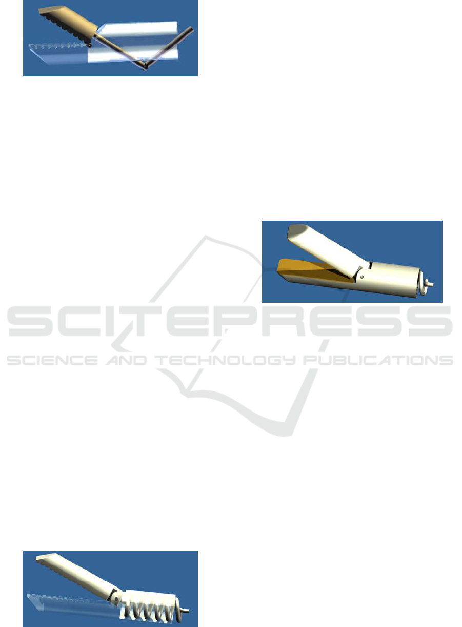
Figure 4: Joint mechanism.
The only possible drawback of the tool is the free
space behind the upper moving jaw of the tool. By
pulling the tool out of the hysteroscope, the upper
jaw may jump around the edge of the insertion
channel, making it impossible for the tool to be
pulled out after surgery. This problem could be
partially avoided by chamfering the back edge of the
upper jaws. This proposed mechanism is shown in
Figure 4.
3.3 Spring Mechanism
The tool is again constructed as a single fixed unit
with a movable part. Its outer diameter is 3 mm. Its
length is not yet determined, it will depend on the
further development and length required to make the
operation convenient. The opening of the jaws is
made possible by means of a peg, which is not
located in the middle of the tool height, but is
located eccentrically. There were two reasons for
this change. The first reason was the possibility of a
larger jaw opening without the need to increase their
length. The second one was structural because of the
spring, so that its end could be better anchored in the
upper jaw. The front of the tool is bevelled on both
jaws to ensure comfortable insertion into the
insertion channel on the hysteroscope.
By using the spring as an operating tool control,
further simplification of the control would be
achieved, however, while meeting the essential
requirements, i.e. comfortable and reliable opening
of the jaws. A compression spring is used which is
connected to the control mechanism the surgeon has
in hand. When compressing this spring, the upper
jaw will open and the spring jaw closes when the
spring is released. This mechanism is shown in
Figure 5.
Figure 5: Spring mechanism.
3.3.1 Modified Spring Mechanism
This model does not differ much from the previous
one. The main change came in the jaws that formed
the series of teeth. At these locations, the groove was
cut to a depth of 1 mm throughout the jaw surface
and the resulting gap was filled with a conductive
surface (electrode) that had the same shape as the
jaw contact surfaces. In order to use high-frequency
current during coagulation. The electrodes continue
through the instrument body to the voltage source.
In addition, it was necessary to wrap the front
edges of the tool to avoid injuries during
manipulation in the uterine cavity.
The last change concerns the peg, which has
been reduced in size so that it is completely hidden
in the tool cavity. This proposed mechanism is
shown in Figure 6.
Figure 6: Modified spring mechanism.
3.4 Material Selection
The correct function of the device and its
components during the required lifetime is
conditioned not only by a suitable choice of the
production technology, but also by the proper design
and choice of the appropriate structural material
from which the component is to be made. The
requirements for the function of the structural
element directly determine its shape and its lifespan,
safety and also its price. (Kratochvíl et al., 2005)
The shape and function of the structural element
are limited by the conditions under which the
structural element has to function and the material
from which it is made. The conditions of operation
of the structural element, in particular the stress and
deformation, the temperature and the environment,
are decisive for the required properties of the
material intended for construction.
Appropriate choices are then determined by the
technology of manufacturing the components and its
price. There is also the issue of the safety factor and
it depends, in addition to the chosen strength
characteristic, on the importance of the construction
element in terms of reliability and lifespan of the
whole structure. (Webster, 1998)
BIODEVICES 2019 - 12th International Conference on Biomedical Electronics and Devices
272
Subsequent selection of the appropriate material
for the specified design element is carried out using
a so-called design index s, according to which the
correct graph can be selected. For this application
the selected graph is Ashby's map. Ashby's maps are
divided by different types of loadings of structural
elements and other mechanical properties. Design
index s must be equal or less than the ratio of
strength σ
f
in MPa to density ρ in Mg/m
3
.
s
≤ σ
f
/ ρ (1)
The Ashby's map is best suited for the specified tool,
which includes the dependence of the maximum
load value (tension) on the maximum density value
of the material while maintaining the minimum
weight condition. According to Ashby's map, the
most appropriate material was selected, which is
Carbon Fiber Reinforced Polymer (CFRP).
(Kratochvíl et al., 2005)
4 STRENGTH ANALYSIS OF THE
DESIGNED TOOL
For strength analysis, it was necessary to determine
what strength the jaws of the operating tool would
be able to develop. That is why an experiment was
made to clarify the magnitude of this strength.
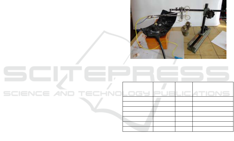
Surgical scissors were used in the experiment.
Furthermore, a stand was used to make the whole
system stable during work. Two clamps for holding
the scissors in the required position and height were
placed in a horizontal position. Two conductive steel
sheets were glued to the jaws to simulate the
coagulation electrodes. However, in order to avoid
the passage of the electric current into the scissors,
an electric insulator was added between the jaws and
the conductive surface. A terminal for the lead cable
was created at their outer end. One of these was
routed through a clutch that has a special gripping
device in order to use common feed wires into the
radio frequency wave generator (RF). The second
one was connected to a conductive pad that was
placed under the scissors' jaws and served as a
pickup area for organic fluids, then also connected to
the RF wave generator.
First of all, the lower jaw of the scissors has been
balanced to eliminate the gravitational force and
prevent spontaneous closure. A weight of 20 g was
used for this balance. Subsequently, the entire body
of the instrument was tested with a multimeter to
avoid possible undesired current flow and no high-
voltage current injuries. In order to add the weights
to the scissors, a holder was used which was
attached to the upper grip portion. By successively
adding weights of 100 g, 200 g, 500 g, 1000 g the
weight value required for sufficient tissue
coagulation was determined to be 1200 g. For the
first measurement, pork brisket without bone was
used as a sample tissue. It has a non-homogeneous
structure and it can represent the composition of
myomas and polyps in the uterine cavity. All
measured values are shown in Table 1. The table
consists of dimensions of the tissue sample, the
weight needed to compress the tissue to enable
proper coagulation, time to complete coagulation
and the percentage of fat in the used sample.
Figure 7: Experiment setup.
Table 1: Time and weight needed for tissue coagulation.
Tissue
dimensions
(mm)
Weight
(kg)
Time
(s)
Fat percentage (%)
5x14x3 1,2 8 80
5x15x2 1,2 2 30
5x15x2 1,2 5 50 - ideal
5x10x4 1,2 4 100
5x10x4 1,2 6 100
5x10x2 1,2 2 95
5x10x4 1,2 45 100 - tough
5 CONCLUSION
The aim of this work was to design a new
electrosurgical tool for hysteroscopy that would
replace a set of existing tools used for surgical
intervention with current hysteroscopes. The
proposed tool should further streamline the
performance, ensure greater speed, easier handling
and increased safety in use. It also has an ability to
be used as simple scissors with electrocoagulation. It
enables the surgeon to easily remove larger myomas
and polyps in the uterus.
The proposed tool was designed and a prototype
was created and tested. Strength analysis was further
performed and an experiment was designed to
Design and Strength Analysis of Laparoscopical Tool for Electrocoagulation Surgery
273

measure the strength needed to clamp the tissue and
time for proper coagulation. Pork brisket was used
as sample tissue. Depending on the tissue structure,
the time needed for coagulation was usually under 8
seconds.
The tool can be used as a replacement for
existing tools for hysteroscopes, it enables the
surgeon to remove myomas and polyps of various
sizes from the uterus cavity and its surroundings.
ACKNOWLEDGEMENTS
The work and the contributions were supported by
the project SV4508811/2101 Biomedical
Engineering Systems XIV'. This study was also
supported by the research project The Czech Science
Foundation (GACR) 2017 No. 17 - 03037S
Investment evaluation of medical device
development run at the Faculty of Informatics and
Management, University of Hradec Kralove, Czech
Republic. This study was supported by the research
project The Czech Science Foundation (TACR)
ETA No. TL01000302 Medical devices
development as an effective investment for public
and private entities.
REFERENCES
K. Citterbart, “Gynekologie”, Praha, 2001. 278 p., ISBN
80-7262-094-0.
Z. Holub, “Laparoskopická hysterektomie”, Praha, 1999.
119 p., ISBN 80-7262-001-0.
Z. Holub, D. Kužel. “Minimálně invazivní operace v
gynekologii”, Praha, 2005, 236 p., ISBN 80-247-
0834-5.
B. Kratochvíl, V. Švorčík; D. Vojtěch, “Úvod do studia
materiálů”, Praha, 2005, 190 p., ISBN 80-7080-568-4.
Schmid, M., Riganti-Fulginei, F., Bernabucci, I., Laudani,
A., Bibbo, D., Muscillo, R., Salvini, A., Conforto, S.
SVM versus MAP on accelerometer data to
distinguish among locomotor activities executed at
different speeds (2013). Computational and
Mathematical Methods in Medicine, 2013, art. no.
343084
D. Kužel, “Gynekologická endoskopie.”, Praha, 1996, p
188 p., ISBN 80-85824-40-X.
M. Penhaker, M. Imramovský, P. Tiefenbach; F. Kozba,
“Lékařské a diagnostické přístroje”, Ostrava, 2004,
332 p., ISBN 80-248-0751-3.
J. Webster, “Medical instrumentation: Application and
design.”, Hoboken (USA), 1998, 691 p., ISBN 0-471-
15368-0.
BIODEVICES 2019 - 12th International Conference on Biomedical Electronics and Devices
274
