
Vision Substitution with Object Detection and Vibrotactile Stimulus
Ricardo Ribani and Mauricio Marengoni
Universidade Presbiteriana Mackenzie, S˜ao Paulo, Brazil
Keywords:
Vibrotactile, Vision Substitution, Deep Learning, Object Detecti on.
Abstract:
The present work proposes the creation of a system that implements sensory substitution of vision through a
wearable item with vibration motors positioned on the back of the user. In addition t o the developed hardware,
the proposal consists in the construction of a system that uses deep learning techniques to detect and classify
objects in controlled environments. The hardware comprise of a simple HD camera, a pair of Arduinos, 9
cylindrical DC motors and a Raspberry Pi (responsible for the image processing and to translate the signal
to the Arduinos). In the first trial of image classification and localization, the ResNet-50 model pre-trained
with the ImageNet database was tried. Then we implemented a Single Shot Detector with a MobileNetV2
to perform real-time detection on the Raspberry Pi, sending the detected object class and location as defined
patterns to the motors.
1 INTRODUCTION
The World Health Organization estimates 285 million
impaired people in the world, being 246 million with
low vision and 39 million completely blind (World
Health Organization, 2012). These people can incre-
ase their environment perception by using technolo-
gies that converts visu al information to different sen-
sors like hear or touch.
The brain plasticity (Bach-y-Rita and Kercel,
2003) has shown the capability of the brain to adapt
to different pa tterns, no matter its source. With some
limitation, the human brain can replace a lost sensor
by using information from other existing sensors in
the body. Some researchers discuss about this phe-
nomena and the sensory substitution (Novich, 2015;
Bach-y-Rita a nd Kercel, 2003; Visell, 2009) and they
cite the ca pability of the brain to change his organi-
zational structure to recognize different patterns. A
common example of this structura l change is the easi-
ness of visually impaired people with the braille wri-
ting system.
Novich ( 2015) has presented a method to allow
deeply dea f users to recognize words from a limited
vocabulary, using encoded audio informatio n captu-
red with a cell phone and sending it to the a wearable
vest that activates a series of vibration mo tors distri-
buted along the user’s back.
The present work show s a prototype that uses
some portable hardware in conjunction with a simple
camera and some vibration motors to send encoded
visual information to the users. The inf ormation co-
mes f rom an o bject detection model and is encoded
using a fixed dictionary. The goal o f this device is not
to completely substitute the vision or other assistance
tools (like th e white ca ne). Since the device is wea-
rable, the user can use the vest and the cane in con-
junction a dding more information about the environ-
ment. A limitation of the white cane is the detection
of objects that are at the top of the user’s field of view,
like a tree branch th at can be detected by a camera.
Additionally to the developed hardware, the sy-
stem has an image processing module to perform in-
ference of deep learning models to detect and classify
objects in the scene. In our first trial to encode visual
informa tion to the vest we performed some tests with
classification models that uses Global Averag e Pool-
ing lay e rs, like the ResNet-50 model (He et al., 2015).
The idea behind trying a classification model was to
have a lighter model in a portable device like a Rasp-
berry Pi, but the limitations on encod ing the informa-
tion made us to use an object detection model. The
chosen model fo r this task was the Single Shot Detec-
tor (Liu et al., 20 15) with a MobileNet V2 ( Sandler
et al., 2018 ) and the performance of this model on the
Raspberry Pi exceeded our expectations.
The paper is organized as follows: in section 2 we
present the related work; in section 3, we describe the
architecture of our prototype, including th e hardware
and software; finally in section 4, results and future
work are discussed.
584
Ribani, R. and Marengoni, M.
Vision Substitution with Object Detection and Vibrotactile Stimulus.
DOI: 10.5220/0007577205840590
In Proceedings of the 14th International Joint Conference on Computer Vision, Imaging and Computer Graphics Theory and Applications (VISIGRAPP 2019), pages 584-590
ISBN: 978-989-758-354-4
Copyright
c
2019 by SCITEPRESS – Science and Technology Publications, Lda. All rights reserved

2 RELATED WORK
In the field of sensory substitution just a few use
image captu re and tactile stimulus (Cancar et al.,
2013; Dakopoulos and Bourbakis, 2008; Pereira,
2006; Johnson and Higgins, 2006; Bach-y-Rita et al.,
1969). The existing tr ials to enco de image to touch
consists in simple methods, like downscale the image
to the size of a matrix of a ctuators o r downscale the
edge image. In some other works that has a focus
on navigation (Cancar et al., 2013; Dakopoulos and
Bourbakis, 200 8; Cardin et al., 2007; Johnson and
Higgins, 2006; Meers and Wa rd, 2005) the signal is
a basic function that tells the user the distance from
objects in the scene and they norma lly use depth sen-
sors. In this cases each motor is activated according
to a point of depth giving the user a spatial perception
of the environment to avoid o bstacles. Considering
the brain capability of adapt, these methods are very
modest ones.
Some other projects also uses image capture but to
generate a different type of output, like audio (Saina-
rayanan et al., 2007; Hub et al., 2004; Gonz´alez-Mora
et al., 1999; Meijer, 1992) or touch using gloves ( Lin
et al., 2012; Meers and Ward, 2005) sending signals
to the the fingertips. All these works that uses diffe-
rent sensors to encode image are evidence that doesn’t
matter the origin of the sig nal, the brain learns how to
deal with the information.
As the goal of this work is to evaluate the brain
capability to classify detected objects using touch, be-
low we describ e the most relevant projects to our re-
search.
2.1 Tactile Vision Substitution System
(TVSS)
Deve loped by Bach-y-Rita et al. (1969), this work is
an early example in the field o f tactile sensory sub-
stitution. Mounted in a dentist chair, it has a 20 x20
vibration motor matrix that projec t the ima ge captu-
red by an analogical TV camera. No preprocessing is
performed on the image.
The TVSS experiments was pe rformed with 6
users, a totally blind person since 4 years old and ot-
her 5 person totally blind since birth. The first ex-
periments included identification of vertical lines, ho-
rizontal lines, diagonal lines and curves. Af te r 20h-
40h of training, the users started to recognize the line
orientation with 100% of accuracy. A next experi-
ment comprised recognition of comb ined lines and
objects from 25 classes, like telephone, chair and cup.
The authors didn’t published the detailed accuracy for
object recognition but exp lained that the users were
Figure 1: Tactile Vision Substitution System (Bach-y-Rita
et al., 1969).
capable of recognize perspective variation and dis-
tance variation in function of the size of the ob je c t.
2.2 PhD Thesis of Mauro Pereira Conti
This research was presented by Pereira (2006) from
S˜ao Paulo University and resulted in a prototype that
performs vision substitution using a camera and an
electro-tactile matrix positioned in the user’s abdo-
men. The image is captu red using a simple camer a
and a customized hardware was developed to activate
the electrodes. T he input image is processed using a
PC for edge detec tion, the edges image is downsca-
led to the size of the matrix an d send to the electrodes
matrix.
Figure 2: System developed by Pereira (2006). Top: Con-
trolled board that activates the electrodes. Middle: Main
board with controller boards connected. Bottom: Electro-
des matrix worn by the user.
The author cites the limitations of real-time pro-
cessing and the lim itation regarding to the hardware
Vision Substitution with Object Detection and Vibrotactile Stimulus
585
size. In the Figure 2 is possible to see big control-
ler boards that makes the system unfeasib le to use in
everyday activities. T he use electrodes also requires
the use of a conductive gel to improve conductivity.
In the fir st experiment, users were subjected to r e -
cognize lines. The group of users with people blind
since birth scored 88% of right answers and the group
with normal vision people score d 70%. In the se-
cond experiment the users were presented with com-
plex geometric symbols, like letter L, square, triangle
and circle. T he group of users with people blind since
birth scored 80% of right answers and the group w ith
normal vision people scored only 44%. The last ex-
periment was intended to show different objects to the
users and all the users scored less than 30% correct.
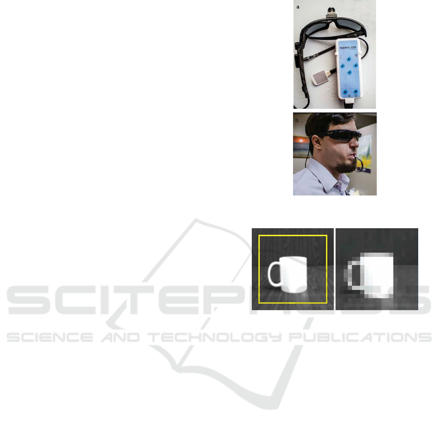
2.3 BrainPort
The BrainPort V1 00 Vision Aid (Stronks et al., 2016)
is a commer cially available d evice that captures the
image using a simple HD came ra and outputs the sig-
nal of the downscaled image into a 20x20 electro-
tactile ton gue display. According to th e product spe-
cification, after some training the user is capable of
identify light variation, detect simple objects, recog-
nize small words and detect movements. This system
is an evolution o f the TDU (Tongue Display Unit),
developed by Bach-y-Rita et al. (1998). The price of
this system is around US$10,000.00 and is available
at USA, Europe and Hong Kong.
The system compr ises a portable processing unit
(Figure 3) that receives images from a came ra moun-
ted in a pair of glasses a nd allows the user to adjust
zoom and contrast. Th e system converts the image to
grayscale and reduces it size to 20x20, mapping each
pixel to a point in the electrodes matrix. The brighter
values are responsible to ac tivate the electrodes in a
higher voltage and the darker values will generate lo-
wer voltage. The Figure 4 shows the captured image
and the output image.
Different kinds of tests were made to evaluate the
BrainPort system, including object identification, text
recogn ition, light variation, contrast and mobility. We
highlight here the results obtained for object identi-
fication and text recogn ition. The experiments we re
made with 18 visually impaired people and the goal
was to identif y if the can identify obje c ts in 4 classes:
ball, banana, text marker and cup. After 15–20 hours
of ge neral device training, the subjects had an average
correct rate of 75% in the object recognition task. For
the word recognition task, 10 words were used having
3-5 letters and the subjects had an average correct rate
of 1 5%. The author relates the poor results to the low
resolution ima ges.
Figure 3: (a) The BrainPort V 100 system. (b) B rainPort in
use by a user. (Str onks et al., 2016).
Figure 4: Example of image captured using the BrainP ort
system and the 20x20 output image. (Stronks et al., 2016).
In addition to the research experiments, clin ical
trials were conducted to allow commercial use appro-
val. The same tasks were applied to 75 totally b lind
individuals. After 10 hours of trainin g, the average
correct rate for object identification was 91% and for
word recognition was 58%.
2.4 VEST
Our prototype is very similar to the VEST (Figure
5). Although it’s a system developed for hearing-
impaired a nd not visually impaired, the work of N o-
vich (2015) stands out by using a more elaborate met-
hod to encode the audio information in a vest with 26
vibro- tactile actuators and expla ins that the inf orma-
tion encoded in these actuators must b e the result of
a function that the brain is capable of decoding wit-
hout generating confusion about the input signal. The
results obtained with the VEST proved the brain ’s abi-
lity to understand com plex patterns.
To e ncode the information from sound to touch
the author uses the k-means clustering method trai-
ned with english sentences. The number of centroids
VISAPP 2019 - 14th International Conference on Computer Vision Theory and Applications
586
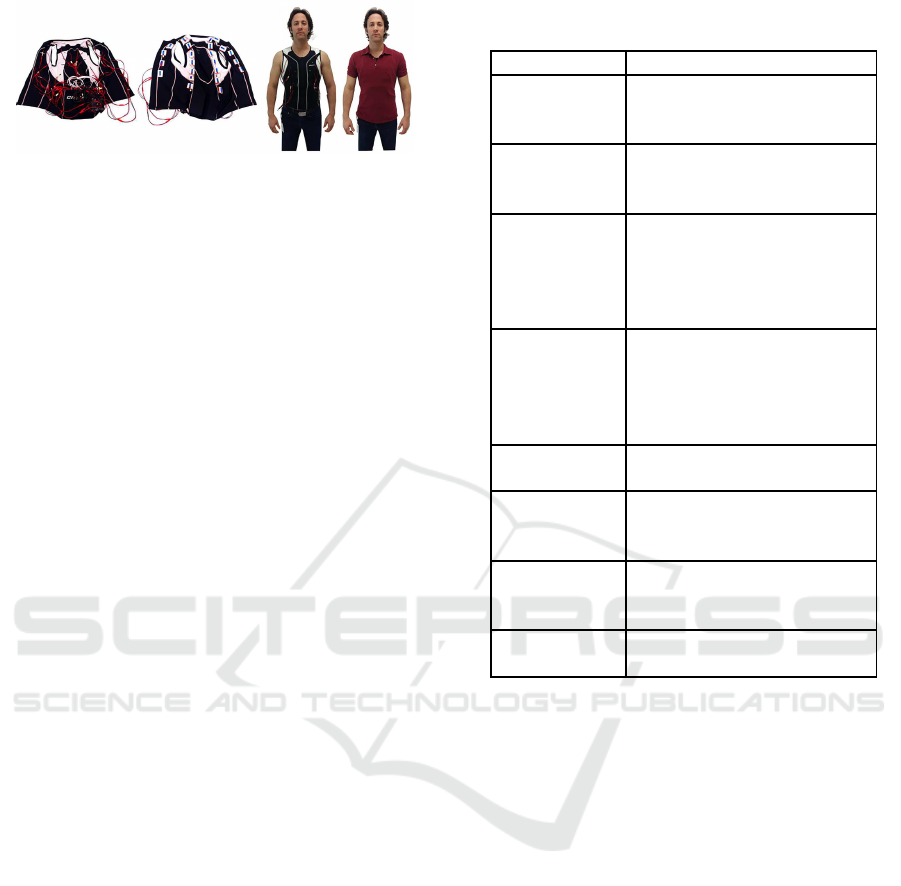
Figure 5: VEST System Novich (2015).
is equal to the number of vibration motors in the vest
and the algorithm is a pplied in certain intervals of
the in put audio data , resulting in 26 frequ e ncy bands
mapped to the moto rs.
After 12 days of training with a 48 words dicti-
onary and after achieving a corre ct rate of 75% in
the tra ining set, the subjects were submitted to a test
set with different words. The performance ranged ap-
proxim ately 35% to 65%, considered a very good re-
sult since the individuals haven’t never seen th e test
set patterns before.
3 PROTOTYPE
Considering the tasks of identify objects in a unknown
environment without any assistance and based on the
theory of the brain’s plasticity, our work proposes a
system similar to the one developed by Novich (2015)
but focused on visually impaired people. The system
proposes vision substitution using a vest with vibra-
tion motors positioned in the back. One of the reasons
for choosing to work with a vest was due to the possi-
bility of the user performing day-to-day tasks without
obstruction of a ny other sense.
Tapu et al. (2014) describes some requirements
needed for an electronic travel aid. T hese require-
ments can be applied to our solution and they are pre-
sented in the Table 1.
3.1 Hardware
In the development of the first prototype, we tried to
meet the maximum possible of requirements quoted
by Tapu et al. (2014). The system created is weara-
ble, portable, reliable, inexpensive, u ser friendly and
does not use cables. The robustness will not be evalu-
ated at first, because the tests will be done in control-
led env ironments. Since it is a prototype, unexpected
situations can oc c ur even in these e nvironments and
user safety will be prioritized.
The first prototype consists of a vest w ith 10 cylin-
drical vibration motors positioned in the back, a pair
of Arduinos model Uno R3, a Raspberry Pi 3 model
B+ and a simple HD camera.
Table 1: Requirements needed for an electronic travel aid.
(Tapu et al., 2014).
Requirement Description
Real-time The system should promptly
send me ssag e s to the user as
soon a s they’re processed.
Wearable It should be worn by the
user. The ears and hands
should be free.
Portable It sho uld be lightweight and
easy to mount, which can
be carried over long d is-
tances, sma ll and ergonomi-
cally shaped.
Reliable Must have a go od cor-
rect rate and reca ll evalua-
tion. However, it must also
have corr ection functions for
unexpected situations.
Low cost It should be comme rcially
accessible to users.
Friendly Simple to use, easy to learn,
no long and exp e nsive wor-
kouts.
Robust The device must resist to d if-
ficult environments and mi-
suse.
No cab les TThere shouldn’t be wires
that limit the user’s mobility.
The Raspberry Pi board was chosen b ecause it is
a low-cost processing unit and porta ble enough to be
carried by the user. This card has a ARM Cortex-
A53 64-bit processor w ith 4 cores of 1.2 GHz, 1 Gb
of RAM and is capable of running different opera-
ting systems. The Raspbian distribution of the Linux
operating system was specifically developed for this
hardware. The Raspbian system is a lightweight and
capable of r unning the TensorFlow software, which
was used for the infe rence proce ss of the deep lear-
ning models.
The choice of the Arduino boards was mainly due
to the ease of prototyping and the nu mber of PWM
ports available to activate the motors. The Raspberry
Pi card has on ly 4 PWM ports, which is little for th e
proposed design. Ther e fore, the task of activate the
motors was cente red on the Arduino board s and the
inference of the models on th e Raspberry Pi.
The cylindrical motors were used due to the fast
response between fully active a nd fully static, also it’s
easy to control the frequency using a standard voltage
of 3V to 5V in the model used. Each motor can be
activated or deactivated to obtain the desire d n umber
of actuators in operation according to the experiment.
Vision Substitution with Object Detection and Vibrotactile Stimulus
587
In addition, it is also possible to change the positions
of the motors, since they are fixed with velcro strips,
which makes it possible to carry out tests with diffe-
rent configurations, a s can be observed in Figure 6.
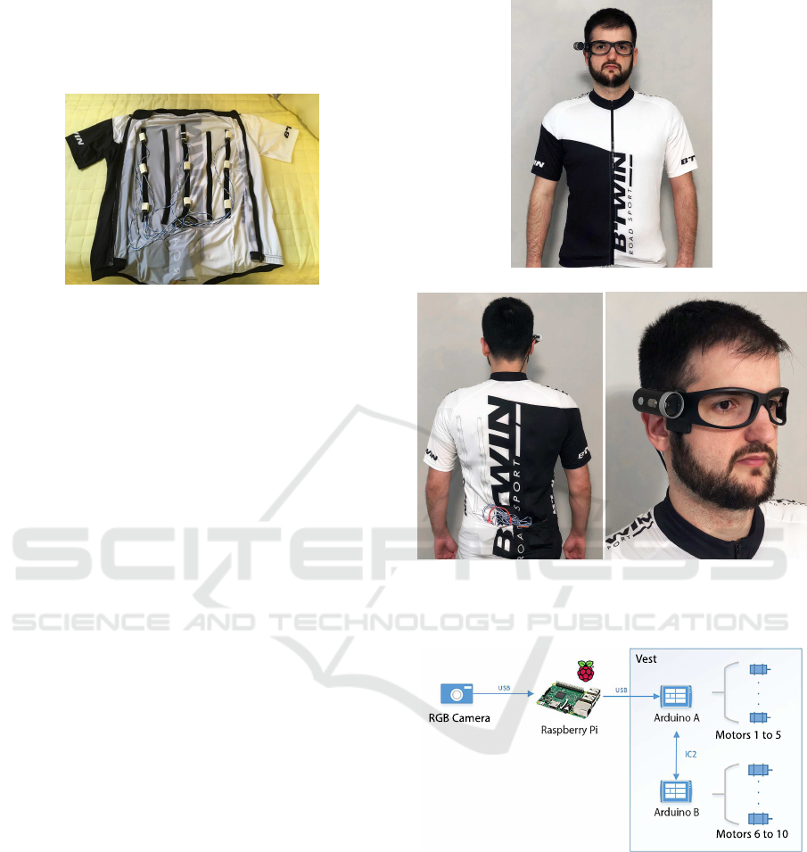
Figure 6: Front facing image of the prototype showing the
internal part. In this image, the motors are configured as a
3x3 array.
The motors were mounted in the intern al back of a
cycling vest. T he vest is made of a an elastic material,
so that they stay close to the body and give the user
the sen sation of vibrations and differentiation whe n
the motor is on or off . For powering the motors an
auxiliary battery was necessary, since the current su p-
plied b y the Arduino was n ot enough. The Figure 7
shows how the vest is when it is worn. The Arduino
boards, th e battery and the Raspberry Pi are placed in
the back pockets. The camera is attached to a regular
eyew ear and connected to the Raspberry Pi.
The camera is connected to the Raspberry Pi
through USB. The captured image is processed using
Te nsorflow to perform inference of a deep learning
model. The output of th e model is post-processed and
sent to the Ard uinos. The signal sent indicates which
motors should be activated. E ach Arduino board has
only 5 PWM ports in the Uno R3 model, so we nee-
ded two boards connected through the I2C protocol.
The figure 8 presen ts a diagram of the prototype that
was developed.
3.2 Software
3.2.1 Classification a nd Localization using
ResNet-50
In our first attempt to encode image to touch we tried
the ResNet-50 (He et al., 2015) m odel pre-trained
with Image N et. Our initial idea was to use a ligh t-
weight classification model that can also output the
spatial location of the object. The ResNet-50 model
uses global average pooling layers allowing us to es-
timate the position of th e classified object using the
process described by Zhou et al. (2015) . Each activa-
tion map of the layer before the global average pool-
ing works as a pattern detector in the image and the
(a) Front
(b) Back (c) Camera detail
Figure 7: Our vest prototype. The boards and batteries are
stored inside t he back pockets of t he vest.
Figure 8: System architecture.
weights that connect the last two layers of the model
represent the contribution of each of these patter ns. In
order to obtain th e activation map that contains the lo-
cation of the classified ob ject, we sum the outpu ts in
the activation layer weighte d with the contributions in
the last layer.
For testing purpo ses we selected two objects and
defined a fixed signal that activates each object. The
first object was a guitar, that activates the vibration
motors horizon ta lly from left to right. The second ob-
ject was a laptop, that activates from right to left. We
VISAPP 2019 - 14th International Conference on Computer Vision Theory and Applications
588
got a pre-train e d model with the ImageNet dataset.
The output of the global average pooling layer in
the ResNet-50 m odel has a 7x7 shape. As we have a
limit of 10 motors in our prototype we needed to re-
duce the size of the global average pooling to 3x3 to
send the informatio n regarding the location of the ob-
ject. A new route was created after the existing global
average p ooling layer with one more global average
pooling layer, downsizing the activation map to 3x3.
The vibration motors in the vest were configured as
the same, allowing us to map th e signal directly to it.
3.2.2 Object Detection with SSD
Even estimating the location of the object through
global ave rage pooling layers, the use of a classifi-
cation model has limitation s fo r the proposed appli-
cation. There is no information regarding the num-
ber of detected objects and it’s always predicting the
class with the greatest pro bability. This is critical in a
system that sends the signal to vibr ation motors, be-
cause the signals are sent to the motor s all the time
causing confusion to the user. To work around this
problem, w e started using an object detection model.
The chosen model was the Single Shot Detector (Liu
et al., 2015) with MobileNetV2 (Sandler et al., 2018)
as bac ken d that has a good balance between perfor-
mance a nd accuracy, 22 mAP in the Microsoft COCO
dataset (Lin et al., 2014) and average 1 FPS running
inference on the Raspberry Pi.
The Microso ft COCO database has 90 classes.
However, in order to attend this experiment we used
objects of only 4 classes (cu p, remote control, scissors
and bottle) and the layout of the motors was modified
in relation to the previous experiment, from 3x3 rows
and columns to 4x2. The activation of the vibration
motors is done per row, where each pair of motors in
each row is activated when detecting an object among
these 4 classes.
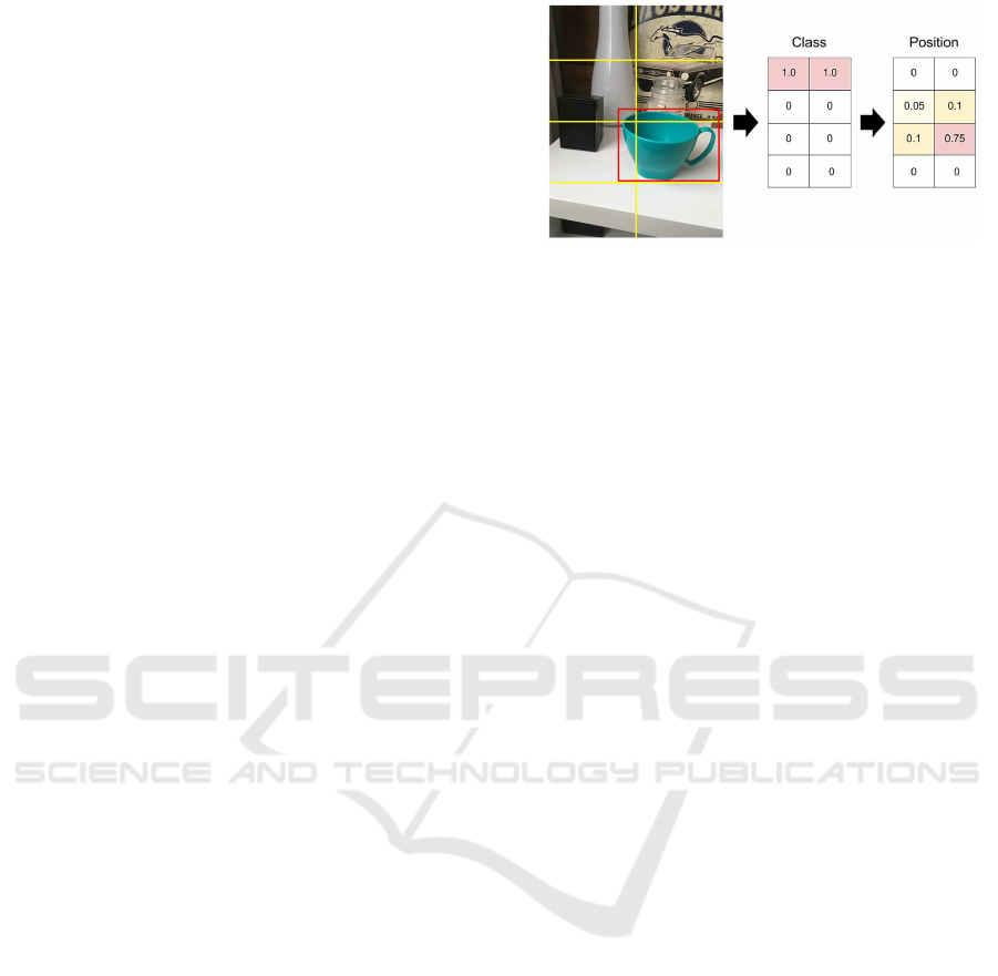
Since th e setup of the motors was modified , we
also changed the output signal indicating the position
of the object. To map the location with r e spect to the
input image, it was divided into 8 quadrants according
to the configuration of the vest, in 4 rows and 2 co-
lumns. Since the m odel already provides the position
and size of the bounding box, we calculated the area
of it in each quadrant obtaining th e intensity value for
each m otor, as can be seen in Figure 9.
Figure 9: Detected object (cup) and the values of activation
for the vibration motors for class and position. Left: Input
image with the 4x2 grid and the detected object. Center:
Values send to the vibration motors to indicate the cup class.
This value is hardcoded fr om a defined dictionary. Right:
Values send to the vibration motors to indicate the position
of the object.
4 DISCUSSION AND FUTURE
WORK
In the first attempt w e used a classification model in
which it was possible to perfor m a simple classifica-
tion in the image and take advantage of the globa l
average pooling layers to locate the object. However,
this model has a limitation for the proposed use case,
mainly by constantly activating the vibration moto rs
that can confuse the user. In o rder to solve this pro-
blem, we decide d to use the SSD obje c t detection mo-
del.
From the tests performed in our labor atory using
the vest with the SSD object detection model, it was
possible to send signals to the vest that repr esents the
objects and the position of this o bjects in sequence.
By using the vest with a real-time detec tion, it was
possible to clearly perceive the difference between
signals sent that r epresents d ifferent objects. The sig-
nal regarding the location of the object seemed a little
more con fusing at first, but after a few minutes of tr ai-
ning the signal started to make more sense. This phase
was intended to check the system operation, including
the communication between all the parts and valida-
tion o f the signal send to the vest, that will enable the
next steps of our research. No evaluation were made
with visually impaired individuals yet.
Novich (2015) explains that the encoded signal
must be a function for the brain to be able to lea rn to
decode the input. Considering this, adjustme nts can
be made in the object detection model to create out-
puts that are functions of th e learned features in the
hidden layers of these models. That is, a possible op-
tion for a next version is to use the f eatures learned by
the network to generate a pattern that is similar when
the input images are similar. To achieve this goal we
Vision Substitution with Object Detection and Vibrotactile Stimulus
589

will perfo rm experiments with clustering algorithms
(such a s k-means), dimensiona lity reduction layers to
match the number of vibration motors, among o ther
techniques that will be investigated .
After having consistent results using the vest in
the laboratory, we plan to perform experiments with
visually impaired users.
ACKNOWLEDGEMENTS
The authors thank Fundo Mackenzie de Pesquisa
(Mack-p esquisa) fr om the Universidade Pre sbiteriana
Mackenzie for the financial support for this research.
REFERENCES
Bach-y-Rita, P., Collins, C. C., Saunders, F. A., White, B.,
and Scadden, L. (1969). Vision substitution by tactile
image projection. 221:963–4.
Bach-y-Rita, P., Kaczmarek, K. A., Tyler, M. E., and
Garcia-Lara, J. (1998). Form perception with a 49-
point electrotactil e stimulus array on the tongue: A
technical note. Journal of Rehabilitation Research
and Developm ent, 35(4):427–430.
Bach-y-Rita, P. and Kercel, S. W. (2003). Sensory substi-
tution and the human–machine interface. Trends in
Cognitive Sciences, 7(12):541 – 546.
Cancar, L., Diaz, A., Barr ientos, A. , Travieso, D., and Ja-
cobs, D. M. (2013). Tactile-Sight: A sensory substitu-
tion device based on distance-related vibrotactile flow
regular paper. International Journal of Advanced Ro-
botic Systems.
Cardin, S., Thalmann, D., and Vexo, F. (2007). A wearable
system for mobility improvement of visually impaired
people. Visual Computer.
Dakopoulos, D. and Bourbakis, N. (2008). Preserving vi-
sual information in low resolution images during navi-
gation of visually impaired. In Proceedings of the 1st
International Conference on PErvasive Technologies
Related to Assistive Environments, PETRA ’08, pages
27:1–27:6, New York, NY, USA. ACM.
Gonz´alez-Mora, J., Hern´andez, A. R., Ramos, L. F. R.,
Dfaz-Saco, L., and Sosa, N. (1999). Development of
a new space perception system for blind people, based
on the creation of a virtual acoustic space.
He, K., Zhang, X., Ren, S. , and Sun, J. (2015). Deep
residual learning f or image recognition. CoRR,
abs/1512.03385.
Hub, A., Diepstraten, J., and Ertl, T. (2004). Design and de-
velopment of an indoor navigation and object identifi-
cation system for the blind. In Proceedings of the 6th
International ACM SIGAC CESS Conference on C om-
puters and Accessibility, Assets ’04, pages 147–152,
New York, NY, USA. ACM.
Johnson, L. A. and Higgins, C. M. (2006). A navigation
aid for the blind using tactile-visual sensory substitu-
tion. In 2006 International C onference of the IEEE
Engineering in Medicine and B iology Society, pages
6289–6292.
Lin, K. W., Lau, T. K., Cheuk, C. M., and Liu, Y. (2012). A
wearable stereo vision system for visually impaired.
In 2012 IEEE International Conference on Mechatro-
nics and Automation, pages 1423–1428.
Lin, T., Maire, M., Belongie, S. J., Bourdev, L. D., Girshick,
R. B., Hays, J., Perona, P., Ramanan, D., Doll´ar, P.,
and Zitnick, C. L. (2014). Microsoft COCO: common
objects in context. CoRR, abs/1405.0312.
Liu, W., Anguelov, D., Er han, D., Szegedy, C., Reed, S. E.,
Fu, C., and Berg, A. C. (2015). SSD: single shot mul-
tibox detector. CoRR, abs/1512.02325.
Meers, S. and Ward, K. (2005). A substitute vision system
for providing 3 d perception and gps navigation via
electro-tactile stimulation.
Meijer, P. B. L. (1992). An experimental system for au-
ditory image representations. IEEE Transactions on
Biomedical Engineering, 39(2):112–121.
Novich, S. D. (2015). Sound-to-Touch Sensory Substitution
and Beyond. Master’s thesis, Rice Universit y.
Pereira, M. C. (2006). Sistema de substituic¸ ˜ao sensorial
para aux´ılio a deficientes visuais via t´ecnicas de pro-
cessamento de imagens e estimulac¸ ˜ao cutˆanea. PhD
thesis.
Sainarayanan, G., Nagarajan, R., and Yaacob, S. (2007).
Fuzzy image processing scheme for autonomous navi-
gation of human blind. Appl. Soft Comput., 7(1):257–
264.
Sandler, M., Howard, A. G., Zhu, M., Zhmoginov, A., and
Chen, L. (2018). Mobilenetv2: Inverted residuals and
linear bottlenecks. CoRR, abs/1801.04381.
Stronks, H. C., Mitchell, E. B., Nau, A . C., and Barnes, N.
(2016). Visual task performance in the blind with the
BrainPort V 100 Vision Aid.
Tapu, R., Mocanu, B., and Tapu, E. (2014). A survey on we-
arable devices used to assist the visual impaired user
navigation in outdoor environments. In 2014 11th In-
ternational Symposium on Electronics and Telecom-
munications (ISETC), pages 1–4.
Visell, Y. (2009). Tactile sensory substitution: Models for
enaction in hci. Interact. Comput., 21(1-2):38–53.
World Health Organization (2012).
Zhou, B., Khosla, A., Lapedriza,
`
A., Oliva, A., and
Torralba, A. (2015). Learning deep features for dis-
criminative localization. CoRR, abs/1512.04150.
VISAPP 2019 - 14th International Conference on Computer Vision Theory and Applications
590
