UAV-based Inspection of Airplane Exterior Screws with Computer Vision
Julien Miranda
1,2,3
, Stanislas Larnier
3
, Ariane Herbulot
1,2
and Michel Devy
1,2
1
LAAS, CNRS, 7 Avenue du Colonel Roche, F-31400 Toulouse, France
2
Univ de Toulouse, UPS, LAAS, F-31400 Toulouse, France
3
Donecle, 201 Rue Pierre et Marie Curie, F-31670 Lab
`
ege, France
Keywords:
Computer Vision, Convolutional Neural Network, Pattern Recognition, Generative Model, Bipartite Graph.
Abstract:
We propose a new approach to detect and inspect aircraft exterior screws. An Unmanned Aerial Vehicle (UAV)
locating itself in the aircraft frame thanks to lidar technology is able to acquire precise images coming with
useful metadata. We use a method based on a convolutional neural network (CNN) to characterize zones of
interest (ZOI) and to extract screws from images; methods are proposed to create prior model for matching.
Classic matching approaches are used to match the screws from this model with the detected ones, to increase
screw recognition accuracy and detect missing screws, giving the system a new ability. Computer vision
algorithms are then applied to evaluate the state of each visible screw, and detect missing and loose ones.
1 INTRODUCTION
In aircraft maintenance,the large majority of visual in-
spections aim at finding defects or anomalies on the
outer fuselage. Those detections are prone to errors
from human operators. Since there is always a gro-
wth in air traffic and increased demands upon aircraft
utilization due to commercial schedules, there is more
pressure on the maintenance operations to be on time
and in consequence more pressure on the workforce
(Marx and Graeber, 1994) (Drury, 1999).
Since the 1990s, there is ongoing research to use
robots to automate the external aircraft inspections.
The aims are often to help the maintenance techni-
cian in his diagnostic and to improve the traceability
of defects and damages in maintenance reports.
First robotic solutions focused on the external sur-
face skin inspection with robot crawling on the air-
plane. Despite a valid proof of concept, some limi-
tations were highlighted for real deployment (Davis
and Siegel, 1993) (Siegel et al., 1993) (Backes et al.,
1997) (Siegel, 1997) (Siegel et al., 1998).
At the beginning of the 2010s, a wheeled collabo-
rative mobile robot named Air-Cobot was built. It is
capable to evolve safely around an aircraft in an en-
vironment which contains some obstacles to be avoi-
ded (Futterlieb et al., 2014) (Frejaville et al., 2016)
(Bauda et al., 2017) (Futterlieb, 2017) (Lakrouf et al.,
2017). Two sensors are dedicated to the inspection.
With a pan-tilt-zoom camera, some inspections are
made visually with computer vision algorithms analy-
zing images taken at stop points or during movements
(Jovan
ˇ
cevi
´
c et al., 2015) (Jovan
ˇ
cevi
´
c, 2016) (Leiva
et al., 2017). The robot is able to elevate a 3D scan-
ner to inspect the lower surface part of the fuselage
(Jovan
ˇ
cevi
´
c, 2016) (Bauda et al., 2018). This robot
is capable to perform tasks autonomously or work in
close collaboration with its operator (Donadio et al.,
2016).
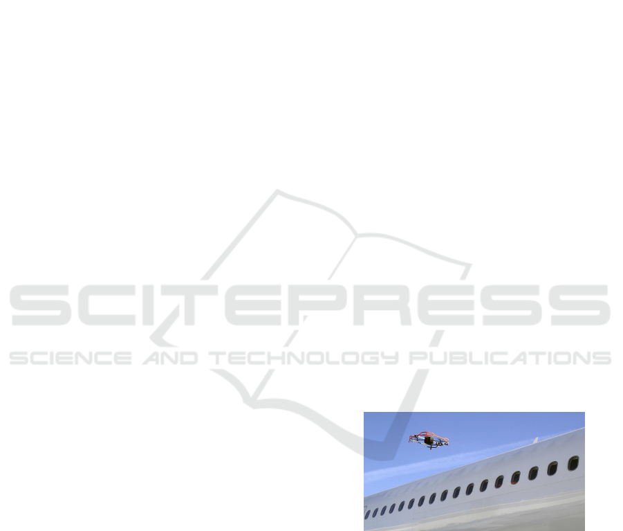
Figure 1: Donecle UAV inspecting an aircraft.
Other approaches focus on cameras located in the
maintenance hangar to inspect aircraft (Rice et al.,
2018). In the second part of the 2010s, some compa-
nies invested research into automatic UAV inspection
such as Blue Bear and Createc with RISER or Air-
bus with Aircam (Bjerregaard, 2018). It is also the
case of Donecle (Claybrough, 2016) (Deruaz-Pepin,
2017). Figure 1 provides a picture of the UAV during
an aircraft inspection in outside environment.
The accuracy of the UAV localization with respect
to the aircraft, making possible a good repeatability of
Miranda, J., Larnier, S., Herbulot, A. and Devy, M.
UAV-based Inspection of Airplane Exterior Screws with Computer Vision.
DOI: 10.5220/0007571304210427
In Proceedings of the 14th International Joint Conference on Computer Vision, Imaging and Computer Graphics Theory and Applications (VISIGRAPP 2019), pages 421-427
ISBN: 978-989-758-354-4
Copyright
c
2019 by SCITEPRESS – Science and Technology Publications, Lda. All rights reserved
421
the image acquisition, so the spatial and temporal fu-
sion of inspection results. The company also provides
a vision software analysis to detect defects from the
images (Miranda et al., 2018). This paper focuses on
the analysis on very common elements of the aircraft:
the screws.
In order to perform an accurate aircraft inspection
of all screws it is necessary to know all of them and
have some knowledge on them. Otherwise like in
(Rice et al., 2018), the proposed method is unable to
always detect all the screws as it is visible in Figure 5
of their paper.
A major topic for aircraft inspection concerns the
inspection of all screws which fix together the fu-
selage parts. A few missing screws can jeopardize the
whole aircraft. Section 2 presents briefly the locali-
zation system and the image acquisition. From those
images, some Zones Of Interet (ZOIs) are extracted
and classified, this is explained in Section 3. Section 4
presents some methods to perform a pairing between
the screws from expected patterns and the ZOIs. Af-
ter the pairing step and depending of the pairs found,
some analysis can be done in order to correct a classi-
fication, identify a missing screw or check if a screw is
turned compared to the nominal configuration. Those
use cases are illustrated in Section 5.
2 NAVIGATION AND PRECISE
IMAGE ACQUISITION
During an inspection with a Donecle UAV, the main-
tenance technician brings the UAV in a suitcase to the
aircraft to inspect. He chooses a mission and places
the UAV in its take-off area.
The UAV localizes itself relative to the aircraft
with laser positioning technology. The inspection can
take place indoor in a hangar or outdorr on the tar-
mac. A navigation algorithm for planning and con-
troling the UAV motions, exploits in real time the
UAV position relative to the aircraft (Claybrough,
2016) (Deruaz-Pepin, 2017). Navigation sensors also
ensure safe operation by preventing collisions with
human workforce and equipment.
There are some advantages of a visual inspection
made from images acquired by an UAV. There is no
contact with the aircraft surface or external power
supply, which is not possible using crawling robots
such as the ones in (Siegel, 1997) (Siegel et al., 1998).
Compared to wheel-robots such as the one in (Dona-
dio et al., 2016), the inspection is faster since the ro-
botic system is less subject to obstacles on the ground
and coverage is more important. It is possible to take
pictures of nearly any part of the aircraft with nearly
any desired angle: camera systems such as the one
in (Rice et al., 2018) are not able to do so. Further-
more, the material is more easily transportable to the
inspection area than the other robotic systems.
Compared to other UAV approaches (Bjerregaard,
2018), a laser-based system enables precise positio-
ning, both indoor in maintenance hangars and outdoor
on the tarmac. The system does not use GPS, beacons
or other external installation: all sensors are onboard
the drone.
In order to have a full accurate aircraft analysis,
the surroundings of the aircraft should be empty and
airframe panels should not be removed. If it is not
the case, there is still the possibility to finish the in-
spection by performing a manual check of the area not
acquired.
This manual check is performed on the tablet soft-
ware and is designed to ease the work of the opera-
tor who has to carry paper documentation when follo-
wing traditional inspection methods. Ergonomic stu-
dies showed that the management of documentation
in aircraft inspection is improved when it is delivered
to the user electronically instead of paper-based wor-
kcards (Drury et al., 2000).
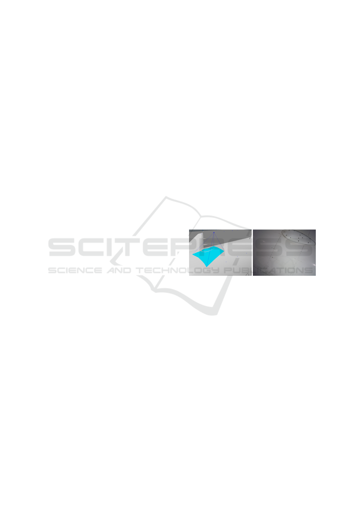
Figure 2: Left, 3D model of the aircraft with the pose of the
camera. Right, the image acquisition.
Figure 2 provides a partial view of the 3D model
and an image acquisition of the blue area highlighted
in the 3D view. This knowledge of the aircraft model
is necessary during navigation to navigate around the
aircraft and to orientate the camera at each acquisition
in order to take desired pictures. Moreover knowing
the UAV position and the aircraft 3D model, it is pos-
sible to predict what objects (and especially, screws)
could be present in the image to be analyzed, taking
into account the position uncertainty.
3 OBJECT RECOGNITION
Object detection is performed using a CNN trained
on annotated images. Several CNN models such as
Single Shot Detector (SSD) (Liu et al., 2016) or the
latest version of You Only Look Once (YOLO) de-
tector (Redmon and Farhadi, 2018) can perform this
task efficiently provided that we adapt those models to
VISAPP 2019 - 14th International Conference on Computer Vision Theory and Applications
422
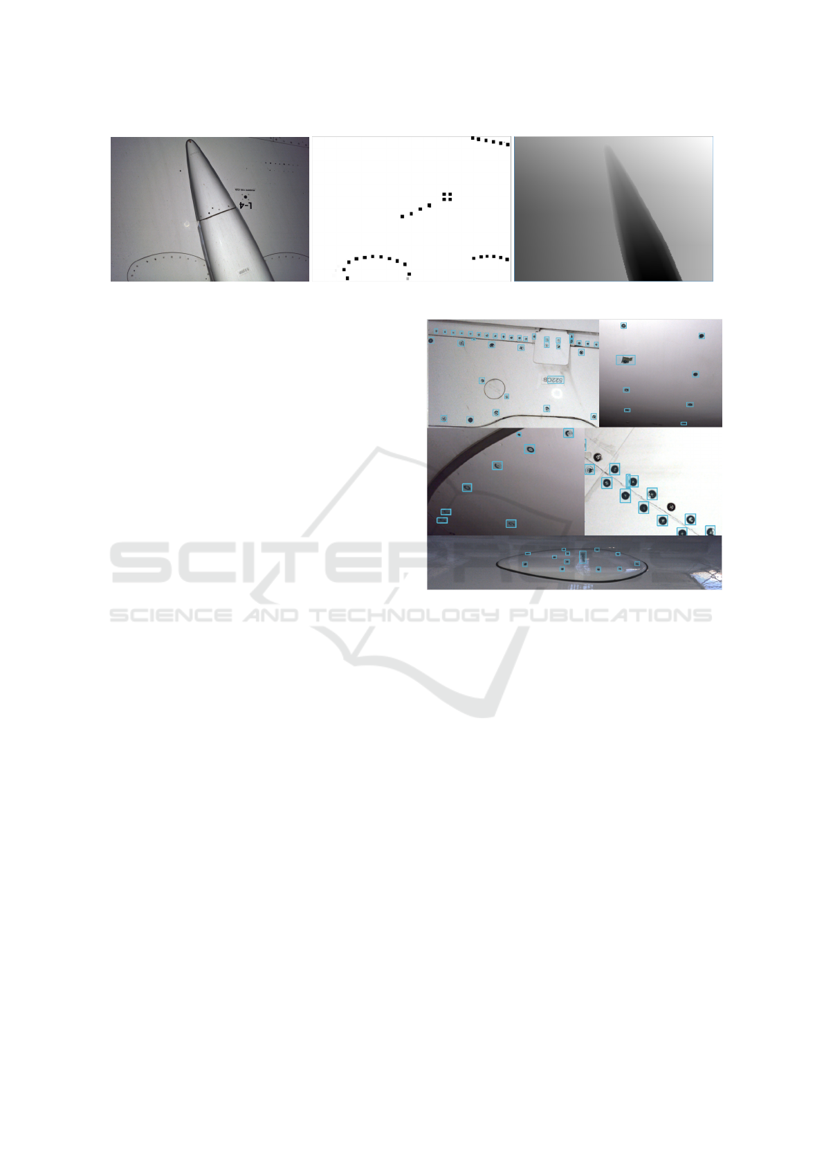
Figure 3: From left to right, acquired image, screw patterns and depth map.
small objects whose size is less than 1% of the acqui-
red image size.
The implemented model can detect and classify
about a dozen of various object classes, including
screws and generic defects. As screws are among
the most common objects on aircraft’s surface and are
distinguishable, the detection and classification’s per-
formance (average precision) is acceptable (recall and
precision > 95%). This system outperforms the met-
hod presented in (Miranda et al., 2018) in similar con-
ditions.
A large variety of geometrical screw patterns can
be detected, among those some defective screws can
be found, see Figure 4 top and middle.
Our system is robust to difficult conditions such as
variable illumination, low light or specular lighting,
see Figure 4 bottom. To achieve this, a dedicated clas-
sifier can reject fuselage specular-induced false posi-
tive detection.
4 OBJECT / CLUSTER PAIRING
4.1 Prior Model Pattern
As a model of the expected objects, one can use the
Digital Mock Up (DMU) that contains the 3D posi-
tion of all those elements. They can then be projected
on the image using flight metatada at acquisition time
(UAV location, camera orientation, etc.). This opera-
tion induces a registration error on objects’ position,
thus it is required to add a further processing.
Our proposed approach is to train a 2D pattern ge-
nerative model via unsupervised learning. Using an
appropriate Generative Adversarial Network (GAN)
architecture, it is possible to learn and to generate
screw patterns from noise.
Then we can use conditional GAN (Mirza and
Osindero, 2014) method to create a pattern associated
to the former object detection. By doing this we com-
plete and regularize the detected ZOI patterns. We
can use aircraft model 2D projection as an additio-
Figure 4: Examples of automated detection. Top right, one
defective screw. Bottom, screws in difficult light conditions.
nal depth map channel for patterns during the training
process, we use both modalities as additional input for
conditional GAN.
Given a prior noise distribution p
z
, such system is
based on the simultaneous training of a generator G
that will generate screw patterns and a discriminator
D that will output the probability that the input x is
from the training set and not from the generator. G is
trained to minimize log(1 − D(G(z)) and D is trained
to minimize log D(X). This can be seen as a min-max
game problem.
We add prior data y which comes from the scene
detection output as conditional input for our multimo-
dal system, so the problem becomes:
min
G
max
D
V (G, D) = E
x∼p
data
(x)
[log D(x|y)]
+ E
x∼p
data
(x)
[log(1 − D(G(x|y)))]
The training data for this generative model can
be obtained by collecting 2D images with identified
screw patterns, or by using virtually projected 3D
cloud points. An example of a 2-channel training
UAV-based Inspection of Airplane Exterior Screws with Computer Vision
423
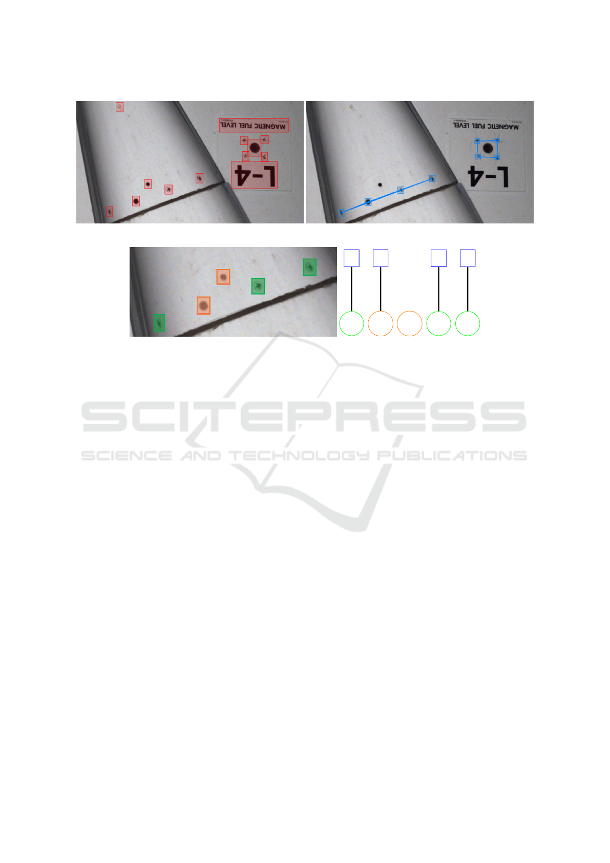
Figure 5: From left to right, detected zones of interest and screw patterns expectation.
s
e
1
s
e
2
s
e
3
s
e
4
s
d
1
h
d
1
h
d
2
s
d
2
s
d
3
Figure 6: From left to right, a cluster of detected zones of interest, associated bipartite graph with the screw pattern expectation.
sample is given in Figure 3 : a pattern map and a depth
map are related to an acquisition. In the depth map,
the darkest pixels are the closest to the camera.
4.2 Pairing Model and Detection
In previous researches on inspection (Fishkel et al.,
2006) (Jovan
ˇ
cevi
´
c et al., 2016), the authors used a bi-
partite graph to have a matching between CAD model
and image features. In the present paper, the propo-
sed algorithms share some similarities. We assume
that we have a theoretical model of screw patterns in
images. Based on the object detection performed by
a CNN, we can easily extract detected ZOIs that are
candidates to be paired with this model.
Thus, given a prior graph and a list of detected
objects in a scene, we can adress the problem as a
minimum cost bipartite matching problem. Based on
Hungarian method (Kuhn, 1955) it is possible to use
shortest augmenting paths to obtain optimal matches
between those graphs. We first have to define the cost
for a detected ZOI to be matched with an expected
one. This function is used to construct a cost matrix.
A simple cost function is the Euclidian distance bet-
ween detected and expected ZOIs. As the screws are
of fixed size and other objects can disturb the desi-
red matching, combining it with size distance leads to
better performance. If the detected ZOIs and the ex-
pected graph sizes differ, the cost matrix is not square.
We add virtual rows or columns filled with high cost
values to proceed matching.
In nominal situation, all the screws are detected
and match the expected pattern. There is a bijection
between those two sets. A threshold on the cost value
avoid matching incorrect elements. If the result of
the pairing is not a bijection between expectation and
detection, there are unexpected or missing elements.
5 SCREW STATE ANALYSIS
5.1 Detect a Missing Screw
Using the described methods, it is possible to detect
the absence of a screw, or the deterioration of a screw
in a pattern. Figure 5 provides the output of the de-
tection in red boxes (left image), and the expected re-
gularized cluster in blue boxes (right image).
If the screw is not detected the prior regularized
graph will have a non-matched element. Figure 6 il-
lustrates correct matches (green boxes from the image
with matches in the bipartite graph), missing screw
detection (orange boxes in the image with an no ma-
tch or incorrect match in the bipartite graph). A cor-
rect match means the paired elements have the same
label (here s), while for an incorrect one, these labels
could be different (here s with h).
If the screw is defective, then it will not be de-
tected as a screw by the classification system, thus the
pairing will lead to a spatial match with a label mis-
match, allowing to warn about the state of the object.
VISAPP 2019 - 14th International Conference on Computer Vision Theory and Applications
424
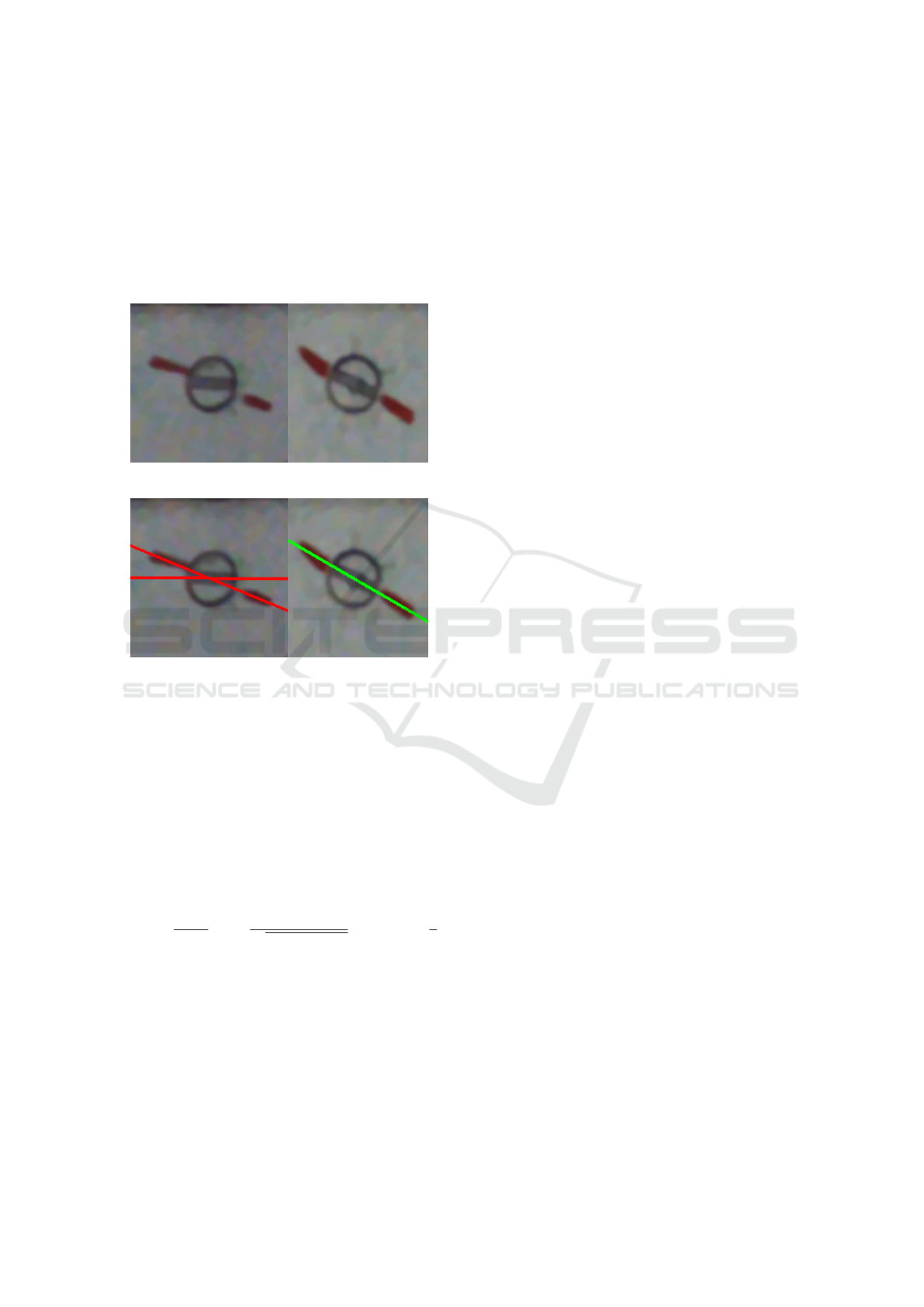
5.2 Check if the Screw is Loose
To render possible the detection of loose screws, on
some maintenance organisations, operators draw a red
segment crossing the screw head in one of the shape
cavities. If the slot is not in the same alignment as the
red segment then it means that the screw is loose. Ex-
amples of slot screw drives are presented in Figure 7.
Figure 7: Example of a loose and tight screw.
Figure 8: Detection of a loose and tight screw.
To analyze the orientation of the screw, it is first
necessary to localize precisely the screw in the ZOI
where it was detected. Then different approaches can
be applied. After some experiments, we decided to
find the screw orientation using a step of the approach
proposed in (Dubosclard et al., 2015) to segment seed
shapes in an image for visual grading applications.
Let Ω be the image domain, ω a screw shape to
compare with the real screw, x ∈ Ω a location. Let E
be a function which takes its values between [0, 1] and
is defined in the following equation:
E(ω) =
1
2|∂ω|
Z
∂ω
*
∇u(x)
p
|∇u(x)|
2
+ ε
2
, n(x)
+
dx +
1
2
where ∂ω is the boundary of ω
h
., .
i
denotes the Eucli-
dian scalar product, n(x) denotes the outward normal
to ω at location x ∈ ∂ω and ε is a regularization para-
meter that discard faint transitions.
This function is sensitive to the normals of the
shape boundary and it is working with high and low
contrast. The used shapes which are compared with
the scene are built from variation in orientation and
size of a slot screw drive.
The next step is to find close but outside of the
screw region, two red areas and fit a line with those
red pixels. Then it is possible to estimate the orienta-
tion of the red segment and compare it with the esti-
mation of the slot one.
Figure 8 illustrates the results of the analysis. For
each subfigures, two lines are drawn. One represents
the orientation of the slot and the other the red line
drawn by the operator. If the difference is too impor-
tant a warning is sent to the operator and the results
are provided in the report.
6 CONCLUSIONS / PROSPECTS
A new visual method to perform external screw in-
spection on aircraft is presented in this paper. This
approach is possible thanks to the accuracy of the
acquisitions made on Donecle’s UAVs. A CNN ap-
proach is used to detect ZOIs with screw objects.
In the detected ZOIs, there could be some missing
screws, see in Figure 4, middle-right, or some false-
negative results. A GAN approach allows to gene-
rate screw patterns both from the 3D model and from
the observed images. The matching between the ex-
pected screws from the model and the detected ones
is made with a bipartite approach. When there is a
matching problem, this is probably due to a missing
or defective screw. After the matching, on well iden-
tifiable screws, algorithms can be executed to check
their orientation. The whole system provides a good
tool for operators to facilitate their job and improve
efficiency, repeativility and traceability.
The proposed solution was demonstrated on air-
planes from Airbus A320 family belonging to a limi-
ted number of airlines but they are easily reproducible
to other types of aircraft or same ones from different
airlines. Given the specificity of this application it
is not easy to find relevant datasets to compare our
method with related works. There is place for im-
provement in the CNN part. The described approach
relies heavily on automated navigation which requires
an accurate aircraft model. If it is not available, then
a prior step of model construction from laser data and
pictures is necessary. Now, the aim is to have more
data for benchmarking our approach and demonstrate
its efficiency.
The obtained results on classification and de-
tection performances increase, while the new de-
fective screw detection abilities demonstrate the inte-
rest of using prior graphs during image analysis. We
assume than those combined models will improve so
we end up with a better object recognition system and
a good prior knowledge on screw patterns for a given
UAV-based Inspection of Airplane Exterior Screws with Computer Vision
425

aircraft.
Based on this proof of concept, the creation of
such condional models will be focused on. This
can be addressed both from a 2D or 3D perspective
: gathering all the 3D classification results of a gi-
ven aircraft model (issued from many UAV’s flights)
to extract recurrent patterns, and using pattern 2D-
generative models conditioned upon detection results.
The presented method can be extended to all ex-
pected objects on the aircraft (marking, rivets, etc.),
or a combination via multi-primitive graph matching.
With more UAV inspections of the same aircraft over
a period of time, it could be envisioned to perform
orientation comparison to respond to loose screws.
REFERENCES
Backes, P. G., Bar-Cohen, Y., and Joffe, B. (1997). The
multifunction automated crawling system (MACS). In
Proceedings of International Conference on Robotics
and Automation, volume 1, pages 335–340.
Bauda, M.-A., Bazot, C., and Larnier, S. (2017). Real-
time ground marking analysis for safe trajectories of
autonomous mobile robots. In IEEE International
Workshop of Electronics, Control, Measurement, Sig-
nals and their Application to Mechatronics (ECMSM).
Bauda, M.-A., Grenwelge, A., and Larnier, S. (2018). 3D
scanner positioning for aircraft surface inspection. In
European Congress Embedded Real Time Software
and Systems.
Bjerregaard, L. (2018). Aircraft drone inspection techno-
logy. MRO Network.
Claybrough, M. (2016). System and method for automati-
cally inspecting surfaces. Patent WO 2016203151.
Davis, I. L. and Siegel, M. (1993). Automated nonde-
structive inspector of aging aircraft. In SPIE, editor,
Measurement Technology and Intelligent Instruments,
volume 2101.
Deruaz-Pepin, A. (2017). Method and system for deter-
mining the position of a moving craft. Patent WO
2017121936.
Donadio, F., Frejaville, J., Larnier, S., and Vetault, S.
(2016). Human-robot collaboration to perform aircraft
inspection in working environment. In 5th Internatio-
nal conference on Machine Control and Guidance.
Drury, C. G. (1999). Human reliability in civil aircraft
inspection. In Human Factors and Medicine Panel
(HFM) Workshop.
Drury, C. G., Patel, S. C., and Prabhu, P. V. (2000). Relative
advantage of portable computer-based workcards for
aircraft inspection. International Journal of Industrial
Ergonomics, 26(2):163–176.
Dubosclard, P., Larnier, S., Konik, H., Herbulot, A., and
Devy, M. (2015). Deterministic method for automatic
visual grading of seed food products. In Proceedings
of the International Conference on Pattern Recogni-
tion Applications and Methods (ICPRAM), volume 1,
pages 212–217.
Fishkel, F., Fischer, A., and Ar, S. (2006). Verification of
engineering models based on bipartite graph matching
for inspection applications. In Proceedings of the 4th
International Conference on Geometric Modeling and
Processing (GMP), pages 485–499.
Frejaville, J., Larnier, S., and Vetault, S. (2016). Locali-
sation
`
a partir de donn
´
ees laser d’un robot naviguant
autour d’un avion. In Reconnaissance des Formes et
l’Intelligence Artificielle (RFIA).
Futterlieb, M. (2017). Vision based navigation in a dynamic
environment. PhD thesis, Universit
´
e Paul Sabatier -
Toulouse III.
Futterlieb, M., Cadenat, V., and Sentenac, T. (2014). A na-
vigational framework combining visual servoing and
spiral obstacle avoidance techniques. In 11th Interna-
tional Conference on Informatics in Control, Automa-
tion and Robotics (ICINCO), volume 2, pages 57–64.
Jovan
ˇ
cevi
´
c, I. (2016). Exterior inspection of an aircraft
using a Pan-Tilt-Zoom camera and a 3D scanner mo-
ved by a mobile robot : 2D image processing and 3D
point cloud analysis. PhD thesis, Ecole des Mines
d’Albi-Carmaux.
Jovan
ˇ
cevi
´
c, I., Larnier, S., Orteu, J.-J., and Sentenac, T.
(2015). Automated exterior inspection of an aircraft
with a pan-tilt-zoom camera mounted on a mobile ro-
bot . Journal of Electronic Imaging, 24(6).
Jovan
ˇ
cevi
´
c, I., Viana, I., Orteu, J.-J., Sentenac, T., and Lar-
nier, S. (2016). Matching CAD model and image fe-
atures for robot navigation and inspection of an air-
craft. In International Conference on Pattern Recog-
nition Applications and Methods (ICPRAM 2016).
Kuhn, H. W. (1955). The hungarian method for the assig-
nment problem. Naval Research Logisitic, pages 83–
97.
Lakrouf, M., Larnier, S., Devy, M., and Achour, N. (2017).
Moving obstacles detection and camera pointing for
mobile robot applications. In Proceedings of the 3rd
International Conference on Mechatronics and Robo-
tics Engineering (ICMRE), pages 57–62.
Leiva, J. R., Villemot, T., Dangoumeau, G., Bauda, M. A.,
and Larnier, S. (2017). Automatic visual detection
and verification of exterior aircraft elements. In 2017
IEEE International Workshop of Electronics, Control,
Measurement, Signals and their Application to Me-
chatronics (ECMSM).
Liu, W., Anguelov, D., Erhan, D., Szegedy, C., Reed, S.,
Fu, C.-Y., and Berg, A. C. (2016). SSD: Single Shot
MultiBox Detector. In Computer Vision - European
Conference on Computer Vision (ECCV), pages 21–
37.
Marx, D. A. and Graeber, R. C. (1994). Human error in
aircraft maintenance. Johnstone, McDonald & Fuller,
Avebury Technical, Aldershot.
Miranda, J., Larnier, S., and Claybrough, M. (2018). Ca-
ract
´
erisation d’objets sur des images acquises par
drone. In Conf
´
erence Reconnaissance des Formes,
Image, Apprentissage et Perception.
VISAPP 2019 - 14th International Conference on Computer Vision Theory and Applications
426

Mirza, M. and Osindero, S. (2014). Conditional generative
adversarial nets. arXiv preprint arXiv:1411.1784.
Redmon, J. and Farhadi, A. (2018). Yolov3: An incremental
improvement. arXiv.
Rice, M., Li, L., Ying, G., Wan, M., Lim, E. T., Feng, G.,
Ng, J., Nicole, M., Jin-Li, T., and Babu, V. S. (2018).
Automating the visual inspection of aircraft. In Aero-
space Technology and Engineering Conference.
Siegel, M. (1997). Remote and automated inspection: Sta-
tus and prospects. In 1st Joint DoD/FAA/NASA Con-
ference on Aging Aircraft.
Siegel, M., Gunatilake, P., and Podnar, G. (1998). Robotic
assistants for aircraft inspectors. IEEE Instrumenta-
tion Measurement Magazine, 1(1):16–30.
Siegel, M., Kaufman, W., and Alberts, C. (1993). Mobile
robots for difficult measurements in difficult environ-
ments: Application to aging aircraft inspection. Ro-
botics and Autonomous Systems, 11(3):187–194.
UAV-based Inspection of Airplane Exterior Screws with Computer Vision
427
