
An Approach to Design Smart Grids and Their IT System by
Cosimulation
David Oudart
1,2
, J
´
er
ˆ
ome Cantenot
1
, Fr
´
ed
´
eric Boulanger
3
and Sophie Chabridon
2
1
EDF R&D, Palaiseau, France
2
SAMOVAR, CNRS, Universit
´
e Paris-Saclay, T
´
el
´
ecom SudParis,
´
Evry, France
3
LRI, CNRS, CentraleSup
´
elec, Universit
´
e Paris-Saclay, France
Keywords:
Cosimulation, FMI, IT, MDE, Smart Grid, Cyber-physical System.
Abstract:
Smart grids are the oncoming generation of power grids, which rely on information and communication
technologies to tackle decentralized and intermittent energy sources such as wind farms and photovoltaic
plants. They integrate electronics, software information processing and telecommunications technical do-
mains. Therefore the design of smart grids is complex because of the various technical domains and modeling
tools at stake. In this article, we present an approach to their design, which relies on model driven engineer-
ing, executable models and FMI based cosimulation. This approach is illustrated on the use case of an insular
power grid and allows to study the impact of power production decisions.
1 INTRODUCTION
Smart Grids are the oncoming generation of power
grids, enabled by information and communication
technologies, taking part into the transformation of
the electrical power landscape. They especially sup-
port the introduction of decentralized and renewable
energy sources in the electrical production, allow pre-
vention, better reactivity and improved response to
events such as electrical failures. Smart Grids are
therefore large-scale critical systems potentially im-
pacting a lot of people. Such systems require thor-
ough verification and validation before their imple-
mentation, and simulation is very valuable to evaluate
various behavioral assumptions. Because they involve
many interdependent technical domains, namely elec-
tronics, software information processing and telecom-
munications, Smart Grids are a typical example of
complex systems to design. Model Driven Engineer-
ing (MDE) principles are well-suited to address the
design and development issues of complex industrial
systems by reasoning on executable models all along
their life cycle (Hutchinson et al., 2011). However,
there lacks a general approach to interconnect mod-
els from different technical domains in a cosimulation
approach for engineering complex systems (Gomes
et al., 2018). These models are designed using dif-
ferent tools for manipulating state machines, activity
diagrams, discrete events or statistical models, and the
accuracy and the predictive value of the cosimulation
depend on a proper integration of these tools and on
the synchronization of their execution. It is therefore
mandatory to ensure the macroscopic alignment of the
models with the business processes, and to maintain
the consistency of the global model through the itera-
tions of the individual models toward a final design.
This paper proposes an approach to assist Smart
Grid designers in evaluating the global behavior of
their solution and to evaluate the impact of energy
production decisions. Our approach is based on MDE
principles and on the FMI standard for the cosimu-
lation of dynamic models, and focuses on computa-
tional and applicative modeling.
2 SIMULATION OF
CYBER-PHYSICAL SYSTEMS
FOR THE INDUSTRY
Our motivation is to cosimulate the different domains
of a Smart Grid: electronics, software information
processing and telecommunications, in order to eval-
uate its global behavior.
We identify specific requirements for the simula-
tion of Smart Grids that can be considered as indus-
trial cyber-physical systems. Different levels of ab-
straction in the models should be supported as the sys-
tem may be too complex for extensive modeling. Be-
cause of that complexity, the knowledge of the global
system is shared between several experts. Our propo-
sition enforces separation of concerns and ensures
370
Oudart, D., Cantenot, J., Boulanger, F. and Chabridon, S.
An Approach to Design Smart Grids and Their IT System by Cosimulation.
DOI: 10.5220/0007407003700377
In Proceedings of the 7th Inter national Conference on Model-Driven Engineering and Software Development (MODELSWARD 2019), pages 370-377
ISBN: 978-989-758-358-2
Copyright
c
2019 by SCITEPRESS – Science and Technology Publications, Lda. All rights reserved

the consistency of the interfaces between the various
technical domains. Additionally, our work targets in-
dustrial contexts which require intellectual property
protection and calls for solutions able to manipulate
black-box models in a cosimulation approach.
Model Driven Engineering (MDE) is an approach
covering the whole life-cycle of a software based sys-
tem, such as Smart Grids, using executable modeling
(Hutchinson et al., 2011). Models are processable in
order to perform automated manipulations like veri-
fications, simulations or transformations. While a lot
of MDE frameworks raise concerns about UI and us-
ability (Abrah
˜
ao et al., 2017), our approach enables
the reuse of existing industry-standard simulators for
each domain of the system.
Functional Mockup Interface (FMI) is a standard
for the cosimulation of dynamic systems allowing the
interconnection of several different simulators in an
integrated execution (Blochwitz et al., 2011). An
artifact compliant with FMI is called a Functional
Mockup Unit (FMU) and is a black-box encapsulation
of a model and its simulation engine. The format of
FMUs protects intellectual property, which is manda-
tory in the industrial context of Smart Grids. FMI is a
standard allowing the separation of domains by subdi-
viding the model of a Smart Grid into several models
and their proper simulation tool, ensuring therefore
modularity and reusability (Gomes et al., 2018).
In addition, information technology (IT) aspects
are not considered in practice, and there is no IT sim-
ulator as such. Enterprise Architecture (EA) aims to
model information, software and technology, often
through the decomposition in several point-of-view
layers with different levels of abstraction. But the
models are usually not executable, and even less sim-
ulable. We draw from previous work (Seghiri et al.,
2016) for modeling and executing EA processes and
extend it by focusing on modeling the IT system for
FMI cosimulation and addressing the issues for inter-
facing the heterogeneous models of a Smart Grid.
3 RELATED WORKS
In the electrical energy community, the challenge of
simulating Smart Grids is not new. (Yang et al., 2013)
sets up an environment to cosimulate Smart Grids
with distributed control. Their approach uses soft-
ware and hardware-in-the-loop simulations, where
real controllers interact with a Matlab simulation of
the plant through UDP and TCP communications.
They particularly addressed the issue of the adap-
tation between event-driven and continuous compo-
nents.
(Nutaro, 2011) explains how a power grid simula-
tor should be designed in order “to accommodate the
requirement for interoperability”. The author devel-
oped his own power grid simulator based on numeri-
cal algorithms instead of only equations to combine
discrete and continuous simulations in one engine.
Sensors, controllers and electro-mechanical compo-
nents are all modeled and simulated with that engine
and a component library written in C++. The simu-
lator also implements an interface for time manage-
ment and the injection of discrete data at runtime.
To integrate a communication simulator, the power
grid models are wrapped in components for the OM-
NET++ or NS2 simulators. This approach is efficient
but provides a very specific solution for the cosim-
ulation of Smart Grids and therefore lacks of exten-
sibility. New behaviors and control equipments are
defined by writing C++ code, so there is little support
for managing the refinement of the components dur-
ing design. Also, using code as models prevents the
use of MDE techniques for generating the wrappers
necessary to interconnect the different simulators and
to check the consistency of the whole simulation.
(Li et al., 2011) developed a framework called VP-
Net for Smart Grid simulation. The VPNet frame-
work provides a cosimulation coordinator imple-
mented in C# to interface the OPNET communication
simulator with VTB, a simulator for power grids with
automated control. The two simulators are also both
extended with interface modules to allow exchanges
with the coordinator. This approach takes only into
consideration the communication and the power as-
pects of a grid. The control part is integrated in the
electrical simulation and there is no support for the
IT aspect, which goes beyond “classical” control in
Smart Grids. Moreover, this approach is tied to two
specific simulators while our goal is to build a frame-
work allowing (with limited development effort) the
integration of any simulator. This is necessary be-
cause companies have developed specific simulators
for handling technical aspects such as transients, har-
monics and unbalanced networks. These legacy tools
capture business knowledge that can be used during
the design and analysis of a Smart Grid.
(Rohjans et al., 2014) notes that current Smart
Grid simulation environments generally focus on one
domain of the system, and expresses the need for
a fully integrated environment handling multi-agent
control, and interactions between these agents and the
power system components. The paper presents a list
of requirements for appropriate Smart Grid simula-
tion tools, such as using time-stepped simulations, or
allowing different paradigms in the models that are
integrated. The authors conclude that there is a gen-
An Approach to Design Smart Grids and Their IT System by Cosimulation
371

eral lack of interoperability, and particularly of “a
standardized and lightweight simulator API to enable
syntactic interoperability (how data is exchanged), a
standardized semantic description to achieve seman-
tic interoperability (what is the meaning of exchanged
data), and a well-defined model-independent scenario
description language (what components are to be sim-
ulated and how they are interconnected)”.
The existing solutions for the simulation of Smart
Grids show what is technically possible and the kind
of results we can expect. However, we would like
to go further and to provide support for an evolving
simulation of Smart Grids, from abstract models with
coarse physical behaviors, up to very detailed models
of the power grid, the telecom network, and the smart
control algorithms.
4 DESCRIPTION OF THE
GENERAL APPROACH
Our approach allows design engineers to simulate the
behavior of their solutions, confronted to several sce-
narios. Based on the results, they can iterate at lower
costs using different leverages in their models, such as
equipment sizing, topology, or software algorithms.
4.1 FMI Cosimulation
The composition of a dynamic model and its simu-
lator is called a simulation unit. A cosimulation is
the interconnexion of several simulation units through
their inputs and outputs, in order to obtain the trace of
the evolution of every exposed variables in the differ-
ent simulation units: the behavioral trace. The FMI
standard defines a common interface to interact with
a simulation unit, which is then called an FMU. It also
constraints the data type of its inputs/outputs to 5 spe-
cific types: BOOLEAN, INTEGER, REAL, STRING
or ENUMERATION. Our approach aims to execute a
cosimulation integrating the FMUs produced by each
domain expert involved in the Smart Grid design.
4.2 Ensuring Proper Interconnection
Between FMUs
One of the main advantages of using a cosimulation
environment is to allow the different experts to de-
velop their own model in autonomy, with a minimal
interference and in parallel with the others (Gomes
et al., 2018). The choice of the FMI standard en-
sures the technological compatibility of each simu-
lation unit, or FMU, with the cosimulation environ-
ment, without having to develop a specific connector
to interface them.
However, the domain experts must share the same
vision of the global design of the Smart Grid and its
expected behavior, to ensure the relevance of their
model and the accuracy of the simulation results.
Hence all experts have to gather before the modeling
phase in order to reach an agreement on a particular
system design, and the distribution of concerns be-
tween the potential domain models.
We want to integrate and formalize this step of dis-
cussion in our approach, in order to ease the transi-
tion with the next steps of modeling and simulation.
Therefore the first step of our approach is to make the
different actors produce together a document called
Inter-domain connections description. This docu-
ment represents all possible interactions between the
different domains, by expressing the static connec-
tions between the future FMUs, in compliance with
FMI concepts such as data types. Hence each expert
has complete authority on the modeling paradigm or
technology, but must generate a FMU of its domain
implementing the precise inputs and outputs defined
in the document called Inter-domain connections de-
scription.
4.3 A 4-Steps Iterative Cycle to
Converge Toward an Acceptable
Design
We decompose the approach into a sequence of steps,
parts of an iterative cycle.
Our approach involves several roles, usually ful-
filled by different actors: the project leader has the
global knowledge of the system, the stakes and ob-
jectives, and expresses the requirements, the domain
experts develop the models of their own domain to
simulate, and generate the corresponding FMU, the
cosimulation architect configures and executes the
cosimulation.
Each step is described by its objective, its method,
its inputs and outputs.
1 - Inter-domain Connections Description: The
step takes as input a global knowledge of the
purpose and of the stakes of the system to
design. It produces the Inter-domain connections
description.
2 - Domain Modeling: The step takes as input the
Inter-domain connections description. Each do-
main expert develops its model and produces a
FMU for his domain, compliant with the data in-
terfaces defined in this document.
MODELSWARD 2019 - 7th International Conference on Model-Driven Engineering and Software Development
372

3 - Cosimulation: The step takes the Inter-domain
connections description as input, and all the do-
main FMUs from the previous step. The Cosimu-
lation Architect deploys the cosimulation accord-
ing to the interconnections defined in the docu-
ment, and executes it. It produces the behavioral
trace of the system.
4 - Trace Analysis & Iteration Decisions: The step
takes the behavioral trace from the simulation step
as input. Various criteria are evaluated (like per-
formance, efficiency, critical threshold) to deter-
mine if the solution is acceptable or not.
5 APPLICATION TO A USE CASE
AND MODELING OF THE IT
BEHAVIOR
5.1 Use Case: Islanded Smart Grid
We chose a real use case from the French power utility
to illustrate our contribution and apply our approach.
It is an island which has an independent power grid
from the mainland, with its own production equip-
ments. A diesel power plant is the main energy pro-
ducer, and is complemented by a photovoltaic farm.
The main issue in the configuration lies in the reli-
ability of the renewable energy supply. Indeed, as
the photovoltaic source relies on sunlight and needs
a clear sky for its production, it makes it as inconsis-
tent and unpredictable as the weather. In order to bal-
ance the production with the consumption, it has to
be sometimes forced to produce below its optimum,
causing economic loss and carbon footprint degrada-
tion. Therefore, a chosen solution is to add a battery
storage to damp the variability of the production, with
the purpose of minimizing the limitations of the pho-
tovoltaic farm.
The efficiency of the system requires an Energy
Management System (EMS) coupled with a Supervi-
sory Control And Data Acquisition (SCADA) in order
to implement an intelligent control of the production.
The target infrastructure of the grid is shown in Fig-
ure 1.
5.2 Interface between Electric and IT
Domains (Step 1)
The project leader makes sure all the domain experts
understand the objectives of the functionalities ex-
pected for the deployed system. Through discussion
and from the chosen design, the actors will identify
Figure 1: Target infrastructure of the “Islanded Smart Grid”
use case.
the simulation needs, the domains to model, and the
nature of the interactions between the considered do-
mains. We define an interaction as an exchange of
data, or a behavioral instruction. These interactions
are flattened into static connections complying with
the FMI constraints by the cosimulation architect, and
finally registered into the Inter-domain connections
description.
For the “Islanded Smart Grid” use case presented
above, we want to verify if a chosen design is opera-
ble and effective. In this paper, we consider only the
IT and the electrical domains, ignoring the telecom
network interaction. We come up with the following
list of interactions between the two domains:
• The grid’s equipments are sending their state-
values to the EMS (PV maximal production, state-
of-charge of the battery, etc.), and the EMS sends
in return control signals (PV-production’s limita-
tion, battery’s power production or consumption,
etc.).
• The EMS can trigger a switch between the cou-
pled state (the diesel plant is connected to the grid
and is the main source) and the islanded state (the
diesel plant is shut down, and the supply is pro-
vided only by the photovoltaic farm and the bat-
tery). Presented in this way, the interaction has
a discrete variability (the EMS punctually trig-
gers the change of state), non-detectable during
FMI cosimulation. It is easy to deduce a con-
nection carrying a piecewise continuous variable:
Grid State control either carries the coupled or is-
landed value.
Therefore, the Inter-domain connections descrip-
tion should look as shown in Figure 2.
An Approach to Design Smart Grids and Their IT System by Cosimulation
373

Connection name
Unit
FMI Type
From
To
PV_Max_Power
Watt
Real
Electric
IT
PV_Limitation_control
Watt
Real
IT
Electric
Battery_SOC
%
Real
Electric
IT
Battery_Power
Watt
Real
Electric
IT
Battery_Power_control
Watt
Real
IT
Electric
Diesel_Power
Watt
Real
Electric
IT
Grid_State_control
Ø
Enumeration
["coupled", "islanded"]
IT
Electric
Figure 2: Use case: Inter-domain connections description.
5.3 Electrical Domain Model and FMU
(Step 2)
We developed a model of the electrical grid with the
Modelica language (Chilard et al., 2015). Modelica
is an object-oriented language used for the modeling
of component-based systems. It is a declarative lan-
guage where classes mainly contain sets of equations,
defining the behavior of the system with no predefined
causality (equality rather than assignment). Model-
ica is well suited for the modeling and simulation of
physical systems like electrical circuits. Moreover
the main simulation engines, OpenModelica
1
and Dy-
mola
2
, implement the FMI standard, allowing the use
and the generation of FMUs.
Our model computes all the electrical values in
every point of the grid, and the state of all the elec-
trical components (battery, plant, etc.). Its inputs im-
plement the Inter-domain connections description de-
fined in Figure 2, and it exposes the wanted variables
as outputs. We finally exported our model into the
FMU format to obtain the Electrical Domain FMU
5.4 IT Domain Model and FMU (Step 2)
As said in section 2, there is a lack of industrial
simulation tool considering the IT aspects of a sys-
tem. Some computational behavior can be evaluated
through algorithms inserted inside models which sup-
port arithmetic operations, or executable scripts im-
plemented with a programming language and linked
with specific connectors or API to the rest of the sim-
ulation. But this nested configuration is difficult to
maintain, so it is preferable and more aligned with
MDE concepts to work with a consistent model of the
IT behaviors of the system. The IT system is itself
a complex sub-system of a Smart Grid. It represents
all the ways the information is created, processed and
used, through software or non-software components.
1
openmodelica.org
2
www.3ds.com
5.4.1 Modeling Method for the IT Sub-system
We propose here a method in two sub-steps to model
the IT aspects of the Smart Grid, by developing sev-
eral models with different levels of details. Hence
several IT experts are involved in this development.
The IT process expert is specialized in design and
IT architecture, whereas the IT applicative expert
is more specialized in computational behaviors, and
software development.
Sub-step 1: IT Process Modeling. The IT sys-
tem has several functions implemented by the vari-
ous software applications of its composition. Each IT
process describes how the IT system behaves in or-
der to achieve a global objective, by making explicit
the chain of functions involved in the realization of
the objective. This sub-step consists for the IT pro-
cess expert in developing the IT process model, a high
level representation of the system, giving structure for
its future refinements. The purpose is to allow one
or several IT applicative experts to work on specific
parts of the refined model while ensuring the consis-
tency of the whole IT domain model.
The IT process model represents the relevant IT
processes involved in the situations to simulate. It
identifies the sequence of functions composing the
different IT processes and their prototype (inputs and
outputs), and makes the IT domain interface explicit.
The chosen modeling language should have enough
expressivity to model deterministic behaviors, events
detection and generation, should allow composite
complex behaviors from simple behaviors, and must
be understandable by non-IT-process experts.
The IT process expert characterizes the functions
of the system, arranges and coordinates them to build
the models of the IT processes. An IT process in
the IT process model can be triggered by internal or
external events and must define the connections be-
tween the inputs and outputs of the functions. The IT
domain interface is explicited and made accessible to
the functions which need to interact with the outside
of the IT domain.
Sub-step 2: IT Domain FMU. The IT process
model from the previous sub-step can not be simu-
lated yet. The goal of this sub-step is to refine this
model with the applicative behavior, in order to ob-
tain a simulable model of the whole IT domain, and
be able to generate an FMU: the IT domain FMU.
The IT applicative experts are in charge of mod-
eling the application behaviors, to refine the IT pro-
cess model to a Simulable IT process model. They de-
velop one Function model for each function defined
MODELSWARD 2019 - 7th International Conference on Model-Driven Engineering and Software Development
374

in the IT process model, the inputs and outputs being
already defined. Then these models must be operated
with the IT process model in one executable artifact,
to generate the IT domain FMU.
For simple behaviors, the Function models may
use the same language as the IT process model, hence
be integrated inside this model thanks to the behavior
decomposition ability of the language, constituting a
Simulable IT process model. However, from our expe-
rience a language that is adapted to process modeling
may not be relevant to describe complex application
behaviors. Textual languages usually require more
skills from the model developer but compensates with
a lot more flexibility, efficiency and accuracy. FMI
is precisely appropriate to execute heterogeneous and
multi-paradigm codependent models through cosimu-
lation. Therefore it may help in this case to constitute
a consistent IT domain model, transposable to FMU
and constituted from several FMU itself.
In this configuration, the IT process FMU gener-
ated from the Simulable IT process model would be
the main orchestrator of the IT domain model execu-
tion. It would coordinate the execution of the Func-
tion models, whether they are part of the IT process
FMU, or out-sided into their own FMU.
The several FMUs are connected together through
a cosimulation scenario, and constitute a cosimula-
tion unit. In order to be consistent with the expected
output of the whole modeling step and produce a
unique FMU for the domain, the IT Domain FMU,
this cosimulation unit is converted to the FMU format.
This operation may require the skills of the Cosimu-
lation expert (cf. section 4).
5.4.2 The “Islanded Smart Grid” Use Case
IT Process Modeling. In our example, we have one
IT process, called Control the production, which im-
plements the objective of maximizing the renewable
part in the energy mix. We chose the fUML
3
lan-
guage for our model, which has enough expressiv-
ity to model deterministic behaviors, events detection
and generation, and allow the composition of com-
plex behaviors from several simple behaviors. fUML
is an executable subset of the well-known UML stan-
dard, acknowledged for its graphical simplicity, hence
understandable for non IT process experts.
We model the process by an fUML “activity dia-
gram”, an “activity” being seen as a process, and an
“action” being seen as a function. The inputs and out-
puts of the functions are fUML objects.
The ITInterface object specifies the IT domain in-
terface defined in the Inter-domain connections de-
3
www.omg.org/spec/FUML
Figure 3: Use case: IT process model in fUML.
scription, figure 2. It is based on stereotypes to make
the direction (in/out) of the data explicit. Figure 3
shows the two diagrams, class and activity, repre-
senting our IT process model for the “Islanded Smart
Grid” use case.
IT Domain FMU. The functions from the IT pro-
cess model are modeled using “opaque actions”,
which are not executable in the fUML standard. The
first objective of the IT applicative experts is there-
fore to develop the executable behavior of these func-
tions in function models. Then the models are made
compatible with FMI and the IT domain FMU is
generated.
The Papyrus tool (Guermazi et al., 2015) and its
plugin named Moka supports the fUML simulation
and FMU export. In this regard, the ITInterface class
is stereotyped with Moka’s embed “FMU” profile,
while its attributes are stereotyped with the “FMI
port” profile. The FMU generator of Papyrus will use
this class to build the interface of the FMU.
Both Retrieve Grid State and Send controls to the
grid functions from the IT process model (Figure 3)
are modeled directly into this model by two fUML
activity diagrams (behavior composition). It mainly
consists in accessing and manipulating the ITInter-
face’s attributes, which will be the inputs / outputs of
the to-be-generated IT Process FMU.
The Compute grid controls function model relies
on an algorithm that manipulates data, and is more
adapted to a textual language. We developed it in
Java, and used the JavaFMI
4
library to implement the
FMI standard and generate the FMU. As a first im-
plementation of an algorithm, we keep it simple and
naive. It implements a decision table to determine if
the battery is consuming or producing, if the PV pro-
duction is limited or maximal, and we do not take any
production or consumption forecasts into account.
4
https://bitbucket.org/siani/javafmi
An Approach to Design Smart Grids and Their IT System by Cosimulation
375
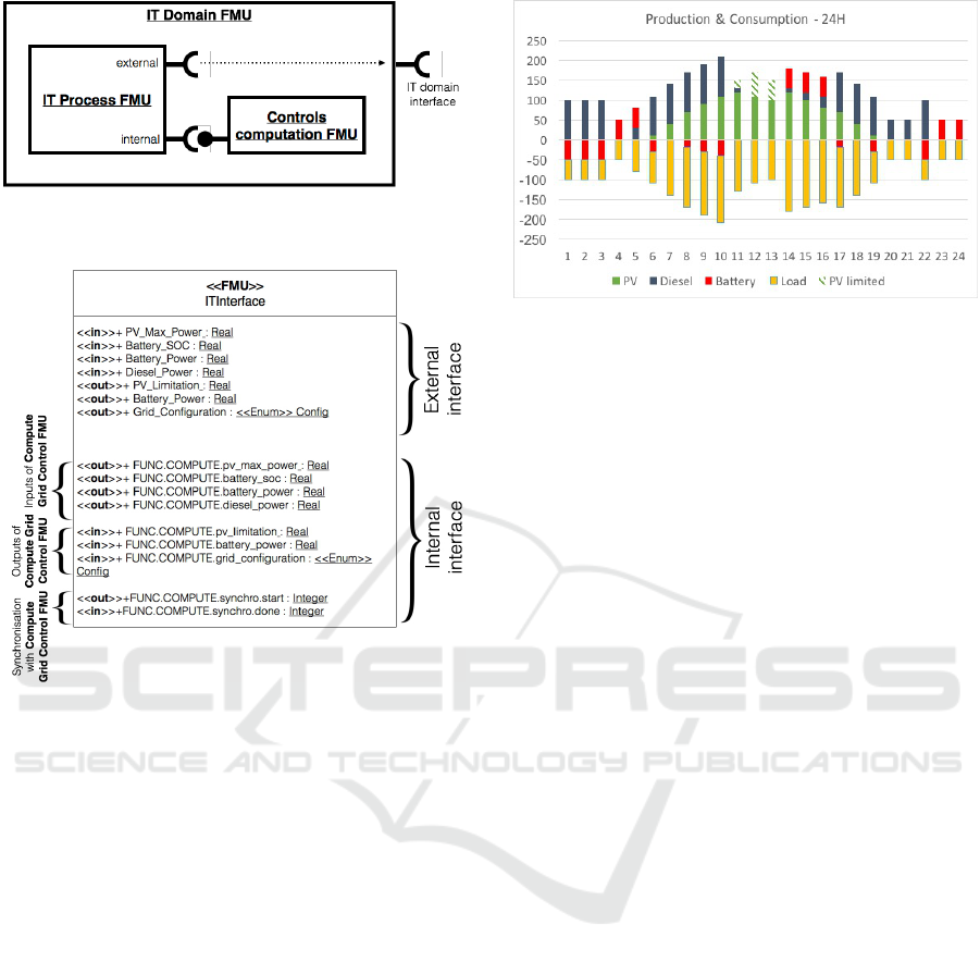
Figure 4: Use case: IT domain FMU composed of the IT
process FMU and one out-sided function FMU.
Figure 5: Use Case: ITInterface class of the Simulable IT
process model.
In order to make the two models interact with each
other during the simulation, we must implement in
both models the corresponding FMI ports.
The DACCOSIM software (Tavella et al., 2016)
is a simulation tool dedicated to FMI cosimulations.
It is handling the composition of FMI cosimulation
scenarios, and can produce an FMU from a cosimula-
tion unit which is already composed of FMUs. Then
the IT Process FMU and the Compute grid controls
FMU are connected together through a FMI cosimu-
lation scenario in DACCOSIM, and encapsulated into
a unique FMU exposing the interface of the IT do-
main (as shown in Figure 4), the IT Domain FMU.
The IT Process FMU exposes FMI ports corre-
sponding to the IT domain, and FMI ports dedicated
to the interaction with the out-sided function models,
here the Compute grid controls function model.
Figure 5 shows the ITInterface class of the Simu-
lable IT process model with these new ports.
Figure 6: Use Case: Production and Consumption on a day.
5.5 Cosimulation and Trace Analysis
(Steps 3 & 4)
The IT Domain FMU and the Electrical Domain
FMU are now generated and available for cosimula-
tion. The Cosimulation Architect defines the cosi-
multion scenario by configuring how these FMUs are
connected, as described in the Inter-domain connec-
tions description. He or she also has to set the various
parameters of the simulation: the starting and ending
time, the step-size strategy (constant, adaptive) to bal-
ance between precision and computation length, the
initial inputs and outputs values if not yet defined...
Again we chose the DACCOSIM software to execute
the cosimulation, as its master (algorithm) of cosimu-
lation shows interesting functionalities improving the
precision of the results (events detection, inteligent
time step-sizing strategies, etc.).
The goal is to evaluate the design choices made
by the design team. In our case, we are evaluat-
ing how the addition of a battery and an EMS im-
prove the management of the production and the ratio
of “green” energy used. Results should be assessed
against quantified requirements in order to classify the
solution either as “effective” or “non-effective”.
Our scenario simulates the normal operation of
the grid on a one day period, for a particular load
curve. Figure 6 represents some of the simulated re-
sults, showing the variations of the consumption and
of the production between the different power sources
of the island (above the horizontal axis is the “produc-
tion” and below is the “consumption”).
The energy balance has been ensured all day (no
black-out), but the PV production has been “limited”
around midday (hatched bars). When we look at other
results we see that the battery was saturated at this
time. There is consequently a clear optimisation po-
tential for our design, either the capacity of the bat-
tery is too low, or the EMS algorithms have to be
improved. For our exemple, we know that the de-
MODELSWARD 2019 - 7th International Conference on Model-Driven Engineering and Software Development
376

sign of the EMS could be strongly improved by tak-
ing into account weather and consumption forecasts.
We should iterate on the current design of the EMS
model, and execute the cosimulation again to visual-
ize directly the effect on the results.
6 CONCLUSION
In this paper, we propose a cosimulation approach and
highlight the purpose of its steps and how they are re-
lated. We provide insights for the realization of each
step, by giving tool propositions and illustration with
a use case. This use case is only a proof of concept, so
the models and behaviors are kept simple. We should
also perform further simulations with different param-
eters (load curves), over longer period to be really rel-
evant on the assessment of the design choices.
In addition we are focusing on the IT Domain, by
expliciting a method to model its behavior at different
levels of detail to manage potential complexity.
We are planning to integrate the Telecom Domain
in a next prototype. We are currently working on in-
creasing the consistency of our approach, by enabling
automated transitions between the different steps, in
order to align more properly with the MDE guide-
lines. The first step on Inter-domain connections has
a strong potential for improvement in this area. Exe-
cutable models are the primary artifacts of MDE ap-
proaches, but the Inter-domain connections descrip-
tion produced in our approach is not executable. It
only gives a hint to the modelers on how to make the
interactions between the models, but nothing prevents
them to do otherwise, or to be mistaken. Moreover,
the fact that all the actors reach an agreement on the
final interface between domains very early in the de-
sign process when no model has been defined yet is a
strong hypothesis of our approach.
Future evolutions of our approach rely on a high-
level architectural model, like the one exposed in
(Andr
´
en et al., 2017), from which domain interfaces
and interconnections can be deduced automatically.
Consistency verification with domain models and au-
tomated transformations should also be facilitated.
Finally, the simulation of a Smart Grid is relevant if
we can ensure that the future implementation and de-
ployment of the system conform to its models.
REFERENCES
Abrah
˜
ao, S., Bourdeleau, F., Cheng, B. H. C., Kokaly, S.,
Paige, R. F., St
¨
orrle, H., and Whittle, J. (2017). User
Experience for Model-Driven Engineering: Chal-
lenges and Future Directions. In MODELS 2017.
Andr
´
en, F., Strasser, T., and Kastner, W. (2017). Engineer-
ing Smart Grids: Applying Model-Driven Develop-
ment from Use Case Design to Deployment. Energies,
10(3):374.
Blochwitz, T., Otter, M., Arnold, M., Bausch, C., Elmqvist,
H., Junghanns, A., Mauss, J., Monteiro, M., Neidhold,
T., Neumerkel, D., and others (2011). The Functional
Mockup Interface for Tool Independent Exchange of
Simulation Models. In 8th Int. Modelica Conf., Dres-
den, Germany, pages 105–114.
Chilard, O., Boes, J., Perles, A., Camilleri, G., Gleizes, M.-
P., Tavella, J.-P., and Croteau, D. (2015). The Model-
ica Language and the FMI Standard for Modeling and
Simulation of Smart Grids. pages 189–196.
Gomes, C., Thule, C., Broman, D., Larsen, P. G., and
Vangheluwe, H. (2018). Co-simulation: A survey.
ACM Computing Surveys, 51(3):49:1–49:33.
Guermazi, S., Tatibouet, J., Cuccuru, A., Dhouib, S.,
G
´
erard, S., and Seidewitz, E. (2015). Executable mod-
eling with fUML and alf in papyrus: Tooling and ex-
periments. In EXE@MoDELS.
Hutchinson, J., Rouncefield, M., and Whittle, J. (2011).
Model-driven engineering practices in industry. In
ICSE 2011, pages 633–642.
Li, W., Monti, A., Luo, M., and Dougal, R. A. (2011). VP-
NET: A co-simulation framework for analyzing com-
munication channel effects on power systems. In 2011
IEEE Electric Ship Technologies Symposium, pages
143–149.
Nutaro, J. (2011). Designing power system simulators
for the smart grid: Combining controls, communi-
cations, and electro-mechanical dynamics. In 2011
IEEE Power and Energy Society General Meeting,
pages 1–5.
Rohjans, S., Lehnhoff, S., Sch
¨
utte, S., Andr
´
en, F., and
Strasser, T. (2014). Requirements for Smart Grid sim-
ulation tools. In ISIE 2014, pages 1730–1736.
Seghiri, R., Boulanger, F., Lecocq, C., and Godefroy, V.
(2016). An Executable Model Driven Framework
for Enterprise Architecture Application to the Smart
Grids Context. In HICSS 2016, pages 4546–4555.
Tavella, J.-P., Caujolle, M., Vialle, S., Dad, C., Tan, C.,
Plessis, G., Schumann, M., Cuccuru, A., and Revol, S.
(2016). Toward an Accurate and Fast Hybrid Multi-
Simulation with the FMI-CS Standard. In ETFA 2016,
Berlin, Germany.
Yang, C., Zhabelova, G., Yang, C., and Vyatkin, V.
(2013). Cosimulation Environment for Event-Driven
Distributed Controls of Smart Grid. IEEE Trans. In-
dustrial Informatics, 9(3):1423–1435.
An Approach to Design Smart Grids and Their IT System by Cosimulation
377
