
Enhanced Waters 2D Muscle Model for Facial Expression Generation
Dinesh Kumar and Dharmendra Sharma
Faculty of Science and Technology, University of Canberra, ACT, Australia
Keywords: Physics-based Model, Muscle Model, Facial Expression, Facial Animation, FACS.
Abstract: In this paper we present an improved Waters facial model used as an avatar for work published in (Kumar
and Vanualailai, 2016), which described a Facial Animation System driven by the Facial Action Coding
System (FACS) in a low-bandwidth video streaming setting. FACS defines 32 single Action Units (AUs)
which are generated by an underlying muscle action that interact in different ways to create facial
expressions. Because FACS AU describes atomic facial distortions using facial muscles, a face model that
can allow AU mappings to be applied directly on the respective muscles is desirable. Hence for this task we
choose the Waters anatomy-based face model due to its simplicity and implementation of pseudo muscles.
However Waters face model is limited in its ability to create realistic expressions mainly the lack of a
function to represent sheet muscles, unrealistic jaw rotation function and improper implementation of
sphincter muscles. Therefore in this work we provide enhancements to the Waters facial model by
improving its UI, adding sheet muscles, providing an alternative implementation to the jaw rotation
function, presenting a new sphincter muscle model that can be used around the eyes and changes to
operation of the sphincter muscle used around the mouth.
1 INTRODUCTION
A widely accepted theoretical foundation for the
control of facial expression generation is the Facial
Action Coding System (FACS). FACS is based on
an anatomical analysis of facial movements and has
been developed by psychologists P. Ekman and W.E
Frieson (Ekman and Frieson, 1977). In 2002, a new
version of FACS was published, with large
contributions by Joseph Hager (Hagar et al., 2002).
It was designed primarily to measure facial
movement relevant to emotion. The aim was to
develop a comprehensive system which could
distinguish all possible identifiable facial
movements. Since every facial movement is the
result of muscular actions on the face, to render
FACS on a computer face model requires a model
on which the FACS Action Units (AUs) can be
easily mapped onto.
In this paper we present an improved Waters
facial model used as an avatar for work published in
(Kumar and Vanualailai, 2016), which describes a
Facial Animation System (FAS) driven by FACS in
a low-bandwidth video streaming setting. The
overall aim is to prepare a facial model on which
FACS AU activations can be directly applied onto
their corresponding facial muscle to generate an
expression or combination of expressions. We note
that the domain of computer facial modelling has
advanced tremendously over the last decade as
described by (Alkawaz et al., 2015) and focus has
shifted more to non-muscle based systems. However
work dedicated to enhancement of muscle based
models in recent years has been few and limited.
Our reasons for selection of Water muscle model
have been due to its simplicity, implementation of
pseudo muscles and the availability of the software
in C++ for the basic model. However Waters face
model comes with limitations in its ability to create
realistic expressions; mainly the lack of a function to
represent sheet muscles, unrealistic jaw rotation
function and improper implementation of sphincter
muscles. Hence in this paper we present a thorough
investigation of the Waters muscle-based model and
provide enhancement to the basic model by:
adding sheet muscles;
providing an alternate implementation to the jaw
rotation function;
presenting a new sphincter muscle equation that
can be used around the eyes;
changes to operation of the sphincter muscle
used around the mouth; and
262
Kumar, D. and Sharma, D.
Enhanced Waters 2D Muscle Model for Facial Expression Generation.
DOI: 10.5220/0007379302620269
In Proceedings of the 14th International Joint Conference on Computer Vision, Imaging and Computer Graphics Theory and Applications (VISIGRAPP 2019), pages 262-269
ISBN: 978-989-758-354-4
Copyright
c
2019 by SCITEPRESS – Science and Technology Publications, Lda. All rights reserved

improving its UI
Through this work we would also like to highlight
the importance of developing muscle-based models
to represent the anatomy of the human face more
accurately in order to generate realistic expressions.
The rest of the paper is organised as follows: In
section 2 we review related work in the field of
facial modelling. Section 3 describes our Facial
Model component FAS. In section 4, we present the
implementation and test results followed by
conclusion in section 5.
2 RELATED WORK
Initial efforts in 3D facial modelling began with
(Parke, 1972) who developed the first parameterized
facial model. (Waters, 1987) and (Magnenat-
Thalmann et al., 1988) follow soon by developing
pseudo muscle based models. The technique of free
form deformations were also used to create facial
expressions for example in (Kalra, et al., 1992).
(Kahler et al., 2001) utilised geometry based muscle
modelling for facial animation whereas (Ostermann,
1998) used the MPEG-4 standard to animate
synthetic faces.
The state of the art in facial animation has
advanced tremendously over the years. There is
increasing effort by researchers to perfect the facial
model to produce quality and realistic expressions.
As a consequence some new and hybrid methods are
continuously being developed using FACS (Tolba et
al., 2018). For example an interactive region-based
linear 3D face model, developed by (Tena et al.,
2011) effectively divided the facial model into
regions with user-given constraints in the form of
markers placed on the face model. These markers
when activated affected only the region in which
they were placed and produced better effects than
using the same markers on a region less model.
(Lewis et al., 2014) in their paper discuss the
practice and theory of blend shape models. Real time
performance based facial animation that enables the
user to control the facial expression of a digital
avatar in real-time is proposed by (Weise et al.,
2011). (Pauly, 2013) and (Bermano et al., 2013)
proposed similar facial performance based models.
There has also been success in producing facial
animation from video or motion capture data. A
paper by (Sifakis et al., 2005) described an
implementation where muscle activations were
automatically determined from motion capture
marker data. Motion detectors or sensors that are
susceptible to movements can be utilised to detect
facial expressions and then animated on a computer
facial model.
Recent research has shown a renewed interest in
using FACS as the basis for generating and
measuring facial expressions. For example (Alkawaz
et al., 2015) combined blend shape interpolation
(BSI) and FACS to create realistic and expressive
facial animation. They trialled their system on four
basic emotions; anger, happy, sad, and fear defined
in FACS. (Tolba et al., 2018) discussed the
applications and limitations of FACS by comparing
with MPEG-4 facial animation based systems.
Articles such as (Ping et al., 2013; Li et al., 2012;
Sandbach et al., 2012; Ersotelos and Dong, 2008;
Alkawaz et al., 2014) provide a good survey of
techniques developed in the area of facial modelling
in recent times while (Noh and Neumann, 1998)
provides a review on theories and techniques
developed decades ago which are a foundation of
facial modelling techniques of the modern world.
3 FACIAL MODEL IN FAS
In this research we use the Facial Animation System
(FAS) described in (Kumar and Vanualailai, 2016).
The original Waters face geometry is retained and
used in the Facial Model component in FAS. It is
based on facial anatomy which dictates that facial
expressions are created by relaxation and tightening
of facial muscles. These muscles on the face can be
categorized into three types: linear muscles, sheet
muscles and sphincter muscles. Mixtures of these
muscle types coordinate to produce each facial
expression.
Waters modelled two types of muscles: linear
muscles that pull vertices under its region of
influence towards the point of attachment on the
skin; and a sphincter muscle around the mouth that
pulls the vertices under its region of influence
towards the center of an ellipse. The third muscle
type (sheet muscles) was not implemented in the
original Waters model but was described in detail in
(Zhang et al., 2001). The equations we use in this
paper are drawn from (Tanguy, 2001; Edge and
Maddock, 2001) which is based on the original
Waters model publication, but expressed in a
simplified form for understanding. The geometry
comprises of 236 interconnected vertices forming
876 triangular polygons. The reader is directed to
(Waters, 1987) to inspect the original visual
representation of the muscles and the facial model.
In our Facial Model we reduced the number of
linear muscles from 24 to 18. Figure shows the
Enhanced Waters 2D Muscle Model for Facial Expression Generation
263
linear muscles retained in our model. Comparing
this with Waters model one can note that linear
muscles around the mouth have been removed as
they produced unrealistic expressions on the facial
model. They have been replaced a sphincter muscle.
We omit the discussion of the equations of the linear
muscle in this paper as this is about the only change
that was made to this vector muscle. The reader is
directed to (Waters, 1987) for a full description of
linear muscles.
3.1 Enhancements to Waters Model
In the following sub sections we describe the
equations of the sphincter and sheet muscles and
modifications to the original model equations to
bring about enhancements to the Waters face model
to a level that allowed us to use it in FAS. We also
describe the new jaw rotation function and
improvements in the user interface to enable
recordings of expressions defined by AUs.
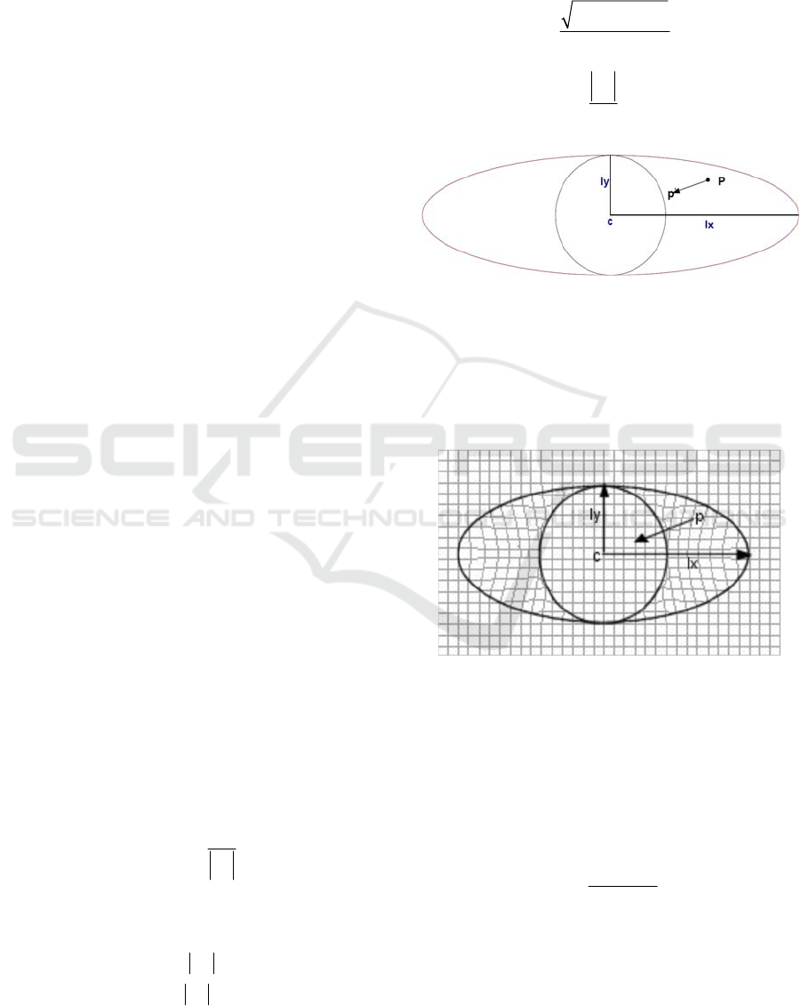
3.1.1 Sphincter Muscles
The sphincter muscle is modeled by Waters as an
elliptical shape and can be simplified to a parametric
ellipsoid. Vertices within the ellipsoid are drawn
towards the center of the ellipsoid (like a drawstring
bag) with maximum movement depended on how far
the vertex position is from the center of the ellipsoid.
Figure 1 and Figure 2 illustrate the sphincter muscle
in the
,xy
plane with the following definitions:
P
: An arbitrary facial skin point.
c
: Epicenter of the sphincter muscle influence
area.
lx
: The semi-major axis of the sphincter muscle
influence area.
ly
: The semi-minor axis of the sphincter muscle
influence area.
The following equation therefore can be used to
compute the new position
'
p
of the vertices at an
arbitrary point P in the
,xy plane within the
ellipsoid.
Pc
pPKD
Pc
(1)
where
K
is the muscle spring constant and
D
is
calculated as:
0
fg for Pc ly
D
for Pc ly
(2)
where
f
is the coefficient of the vertex displacement
for the sphincter muscle in the xy plane, and g is
the proportional distance of the vertex position from
the center of the ellipse, i.e.,
22 22
1
xy
ly P lx P
f
lxly
(3)
Pc
g
lx
(4)
Figure 1: Sphincter muscle model.
The calculation of
D
above protects the central
area of the ellipse (bounded by a circle with radius
equal to
ly
) from vertices from piling up on top of
each other towards the center of the ellipse by
muscle contractions.
Figure 2: Vertices contracting towards center of sphincter
muscle. (Edge and Maddock, 2001).
Equations 1-4 simulate the working of the
sphincter model in 2D. In real lips, the skin
protrudes (bulges) towards the center of the lips,
hence displacement in the z axis is needed for 3D
visualisation. This can be achieved by calculating
for
z
p
as:
(1 )
zz
Kfg
pP
(5)
where
Z
is a constant greater than 0 and is used to
control the peak of the protrusion. Implementation
of the sphincter muscles around the mouth is shown
in Figure 3. The example expression is created with
GRAPP 2019 - 14th International Conference on Computer Graphics Theory and Applications
264
0.3K and 10Z . In this paper we modify the
original Waters program to use three sphincter
muscles; one each around the eyes and one covering
the mouth opening area. The sphincter muscle used
around the mouth area is derived from Waters
original sphincter muscle equation where the
vertices converge towards the centre of the muscle.
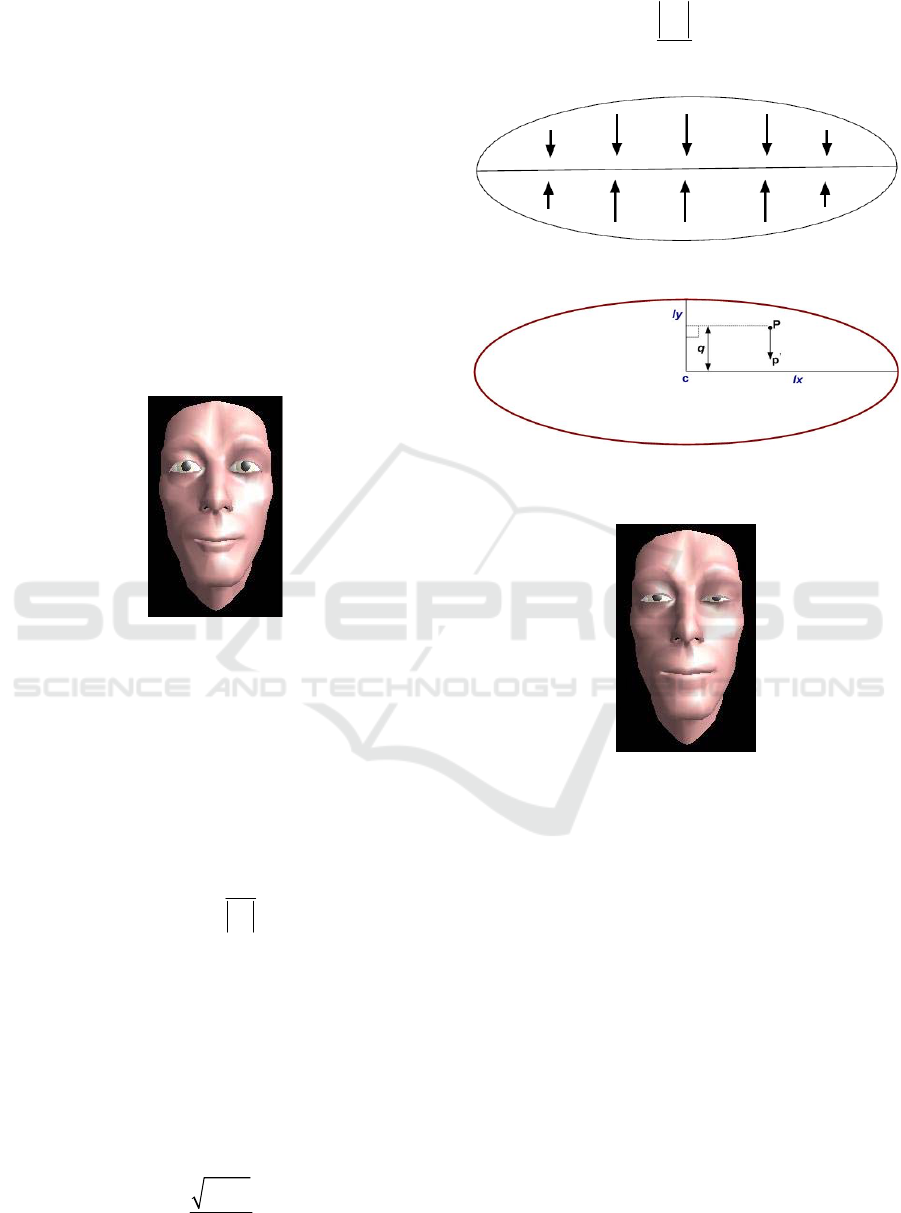
However the orbicularis oris muscle that surrounds
the eye behaves a bit differently. It does not have the
ability to pull the corners of the eyelids towards the
center of the eye. Instead it is only able to pull the
upper and lower eyelids towards each other. Hence
to use the above sphincter equations for the eyes it
had to be modified so that the vertices converge
towards the semi-major axis of the ellipse defining
the influence area around the eyes. This gives the
model the ability to “squint” eyes.
Figure 3: Application of the sphincter muscle on the area
round the mouth.
Figur illustrates our eye sphincter muscle in the
ݔݕ plane with the same definitions as for the normal
sphincter muscle. We note here that the
displacement is along theݕെܽݔ݅ݏ. The new
equation to compute the new position
ᇱ
of the
vertices at an arbitrary point ܲ in the ݔݕ plane within
the ellipsoid in Figure 5 is:
Px
pPKD
Px
(6)
where
K
is the muscle spring constant and is
calculated as:
Dfg
(7)
Here,
f
is the coefficient of the vertex displacement
for the sphincter muscle along the
yaxis
plane
and
g
is the proportional distance of the vertex
position perpendicular to the
x
axis , i.e.,
22
1
y
ly P
f
ly
(8)
Px
g
ly
(9)
Figure 4: Vertices converging to the semi-major axis.
Figure 5: Sphincter muscle diagram for use around the
eyes.
Figure 6: Using sphincter muscles around the eyes.
0.2K
for left eye (to the reader) and
0.4K
for the
right eye.
30Z
.
For displacement in the
x
axis direction, the
same formula as equation (5) is re-used, where
Z
is a
constant greater than 0. A small value for
Z
causes
the eyelids to bulge out, hence in our
implementation we have set this constant to 30,
which achieves good results. Figure 6 shows a visual
of the application of the new sphincter muscle
activation around the left eye.
3.1.2 Sheet Muscle Model
Unlike the linear and sphincter muscle, sheet
muscles are made up of a series of almost-parallel
fibres spread over a rectangular area. The
displacement of vertices therefore is towards one
end of the rectangle with the other end of the
Enhanced Waters 2D Muscle Model for Facial Expression Generation
265
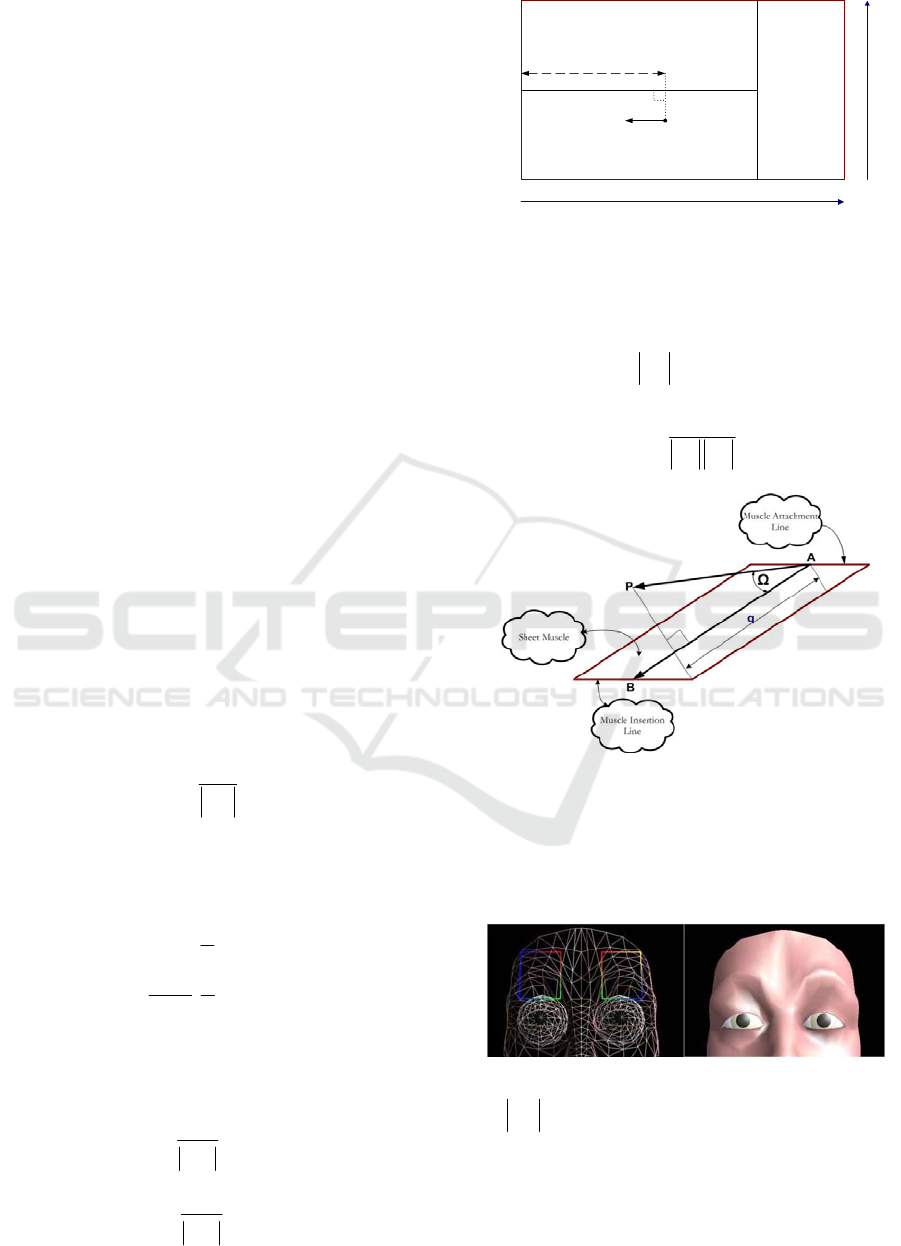
rectangle attached to the bone with maximum
displacement towards the attachment point of the
sheet muscle to the bone. In anatomy, sheet muscles
models muscles such as the frontalis which is
located on the forehead on a human face. Waters in
his face program instead used linear muscles for the
forehead and do not provide a description of sheet
muscles in (Waters, 1987). Hence we use the
description of sheet muscles from (Zhang et al.,
2001). However to achieve the desired effect in our
effort to produce realism in the expressions created
we use Waters linear muscles combined with two
sheet muscles (one on each side of the forehead).
Figure 7 illustrates the sheet muscle with the
following definitions:
P
: An arbitrary facial skin point.
12
,
A
A : Boundary points defining the attachment line
of sheet muscle to bone.
12
,ll: Boundary points defining the insertion line of
sheet muscle to skin.
c
A
: Middle point of sheet muscle attachment line.
c
l : Middle point of sheet muscle insertion line.
,
L
W
: Length and width of the rectangle defining
the zone of influence of the sheet muscle
respectively.
i
l : Distance between arbitrary skin point
P
and the
attachment line.
The new position
p
of the vertices at an arbitrary
point
P
in the ,,
x
yz plane within the rectangular
zone of influence can be calculated as.
cc
cc
A
l
pKD
A
l
(10)
where
i indicates the values of the ,,
x
yz
coordinates of the vertex. Here,
K
is the muscle
spring constant and
D
is calculated as:
cos((1 ) 0 1
2
1
cos(( ) 1
2
1
n
n
n
for
D
for
(11)
where
n
is the sheet muscle strength factor and set
at 1 in our implementation. Here,
i
and
are
calculated as:
i
cc
q
A
l
(12)
cc
L
A
l
(13)
Figure 7: Sheet muscle model.
The relationship between the rectangular sheet
muscle and the arbitrary point
P
is shown in Figur.
Therefore
q can be calculated using the following:
cosqAP
(14)
.
arccos 180 /
AP AB
where
AP AB
(15)
Figure 8: Relationship between
P
and the sheet muscle
for calculation of
q .
The placement of sheet muscles on our face
geometry and its effect on raising the forehead is
shown in Figure 9.
Figure 9: Implementation of the sheet muscles.
0.4K
,
11
2LAl
.
3.1.3 Jaw Rotation
In order to create more convincing expressions it is
important for the facial model to allow for jaw
P
p
’
A
1
A
2
A
c
L
W
l
1
l
2
l
c
q
GRAPP 2019 - 14th International Conference on Computer Graphics Theory and Applications
266
rotations. The human jaw is made up of two parts
namely the upper and lower jaw. The upper jaw
remains fixed while it is the lower jaw that moves.
Waters models the moving lower jaw relative to the
pivot point of the facial model mesh rather than
employing any muscle technique. In his model the
jaw contains vertices of the lower part of the face
which is rotated along the
yaxis
and zaxis
.
Hence this rotation can be explained using the
following definitions and equations.
P
: Vertex forming the lower jaw.
K
: Angle of rotation of the jaw vertex relation to
the root of the facial mesh and is a value between 0
and 4 with 4 indicating the maximum opening.
cos sin
180 180
:
yy z
KK
pP P
f
or rotationalong y axis
(16)
sin cos
180 180
:
zyz
KK
pPP
f
or rotation along z axis
(17)
This formula is applied on all vertices that form the
jaw. The animator therefore has to specify manually
in advance which vertices would be part of the jaw
of the face. Adjusting the value of
K
simulates jaw
opening and closing with maximum rotation
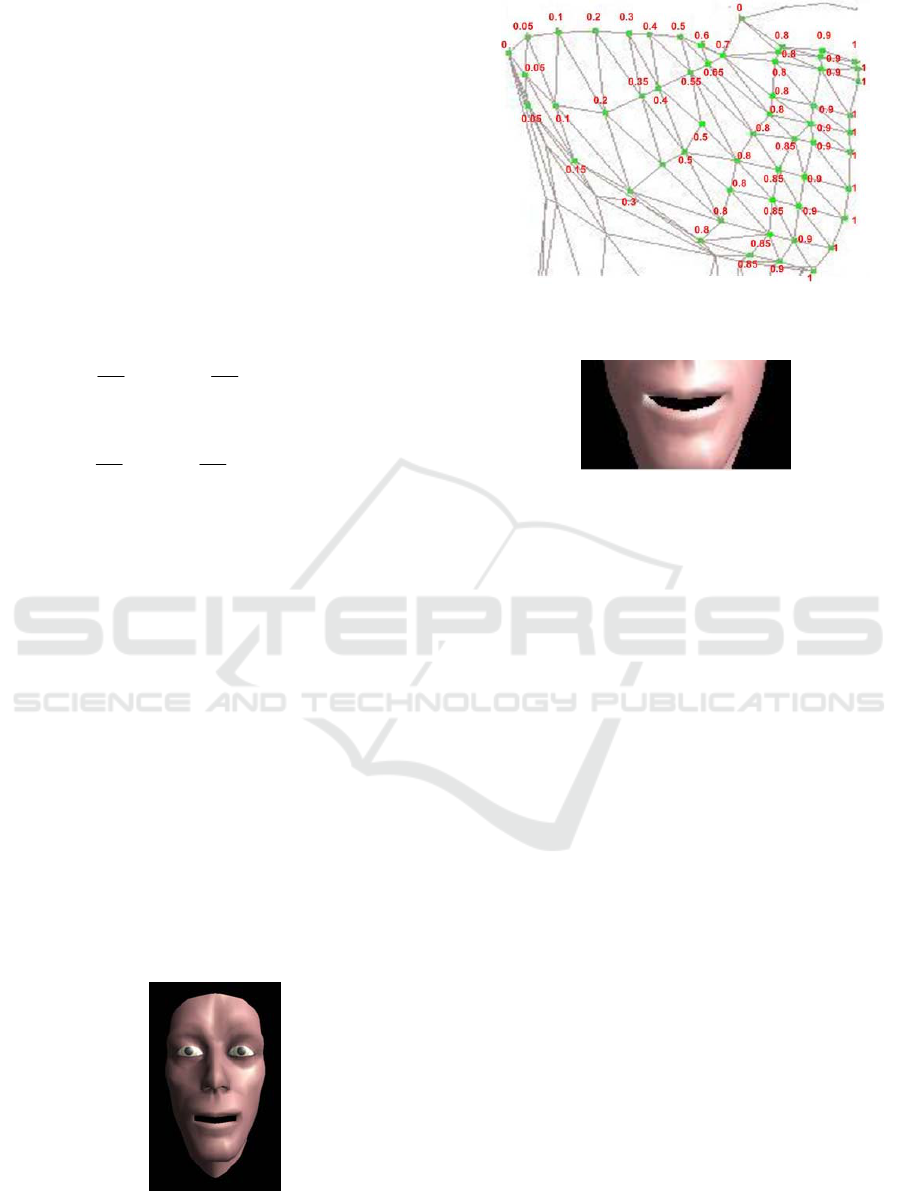
produced at the center of the lower lip. This however
creates discontinuity at the corners of the lips as
reported by (Zhang et al., 2001) and illustrated
Figure 10. To keep the cohesion at the corner of the
lips we have given each vertex forming the
moveable part of the lower jaw a weight value in the
range 0.0 to 1.0 depending on its proximity to the
center of the lips. Since the formula above created
maximum rotation at the center of the lip, all
vertices of the lower jaw around the center are
allocated a higher weight value with decreasing
weights towards the corner of the lips. Hence the
corner points of the lips are allocated a weight of 0
meaning no rotation.
Figure 10: Discontinuity at the lip corners. (Parke and
Waters, 1996).
Figure 11: Weights allocated to vertices forming the lower
part of the jaw.
Figure 12: Jaw drop correction.
Figure 11 illustrates the allocation of weights to
vertices forming the lower jaw. After
p
has been
determined from equations (16) and (17), it is fed
into the following two equations to determine the
final position of vertex
P
. Here
w
is the weight at
P
. Figure 12 shows the improvement in the jaw
rotation function.
(1 )
:
yy y
ppwP w
f
or rotationalong y axis
(18)
(1 )
:
zz z
ppwP w
f
or rotationalong z axis
(19)
4 IMPLEMENTATION IN FAS
The original Waters face geometry is retained and
used in our project. In addition to the 18 linear
muscles, our model introduces 2 sheet muscles and 3
sphincter muscles. Figure 13 shows all the
implemented muscles in our model. The
manipulation of these muscles to generate facial
expressions is handled via the Expression Editor in
FAS (Kumar and Vanualailai, 2016). Given the
nature of this research the realism of the expression
generated in validated by visual inspection using
FACS as a guide.
Enhanced Waters 2D Muscle Model for Facial Expression Generation
267

Figure 13: Implemented muscles in our Facial Model.
4.1 Expression Editor
The Expression Editor in FAS gives the user control
over all the muscles (including the jaw) used in our
face model hence allowing a wide range of
expressions to be generated with ease. Since our aim
is to animate facial expression based on FACS AUs,
it gives the flexibility to generate expressions that
can approximate the various AUs defined in FACS.
Using the expression editor the user can manipulate
one or more muscles to match a particular AU
expression. During this activity the calibration is
rendered in the graphics window for the user to note
the deformations on the face model. This allows the
user to fine tune the expression. Once the desired
expression is generated to a satisfactory level it can
then be recorded with the AU number as an
identifier. There is also the possibility to modify an
existing AU expression if desired by the user. A
total of 64 AU expressions can be defined.
A minimum value of 0.0 and maximum value of
2.0 can be chosen as activation values for each
muscle. Beyond activation value of 2.0 gives
unrealistic results as far as facial mesh deformation
is concerned. However the user can use a value from
0.0 to 4.0 (inclusive) for the jaw control.
By the definition of FACS, complex facial
expressions are generated by applying one or more
individual AUs. When these AU expressions are
programmed and stored in our system, it gives us the
possibility to generate many other compound
expressions simply by using combinations of AUs.
4.2 Suitability of Waters Muscle Model
for Facial Animation
Unlike techniques where producing animation
requires direct manipulation of the facial mesh,
Waters muscles are independent of the facial mesh.
This means that the animator has the freedom to
change the facial mesh yet still achieve the same
effect as in using the original mesh. This allows
flexibility in using different character mesh
topologies. It allows for compact representation of
facial geometry where the only information needed
are the muscle parameter values and the skin mesh
data in order to produce expressions. The muscle
functions work on triangulated vertices, which most
graphics hardware are optimized to use, hence
rendering is fast. Further expression parameters can
control groups of muscles at once resulting in
multiple muscle deformation applied to the facial
mesh. The problem areas include the difficulty of
placing muscles on the geometry of the face which
obviously has to be done manually. The muscle
functions basically represent flat architectures hence
they may not be attached to the skin (facial mesh) at
all. Due to this, muscle curvature and volume is also
not taken into account. At times during animation
some mesh vertices can fall prey to influence from
multiple muscle actions, though this problem can be
solved by taking “average” influences of the muscle
on the vertex. Overall given that FACS AUs map
directly to facial muscles, a muscle based model is
desirable.
5 CONCLUSIONS
The Waters muscle model opens a gateway to
excellent research in facial animation controlled by
muscles. They have been used and tested widely by
researchers over the years. Given the aim of our
project to generate facial expressions governed by
FACS, and that FACS basically describes
expressions based on affected muscles on the face,
Waters muscle model becomes the ideal choice for
use since it allowed easy mapping with FACS AUs.
However we do note the advancements in facial
modelling techniques over the years which are not
muscle based but may have potential in mapping
with FACS AUS. The modular design of our FAS
will allow our Facial Model component to be
replaced with a different modeling technique with
ease. Future directions of muscle based model will
be the development of 3D muscles with different
shape, size and volume to mimic natural muscles;
expand and contract with volume displacement
techniques. Using such design we shall be able to
model real facial expression effects.
GRAPP 2019 - 14th International Conference on Computer Graphics Theory and Applications
268

REFERENCES
Alkawaz, M. H. et al. (2015). Blend Shape Interpolation
and FACS for Realistic Avatar. 3D Research
(Springer Link), 6(6).
Alkawaz, M. H. et al. (2014). Facial Animations: Future
Research Directions and Challenges. 3D Research
(Springer Link), 5(12).
Bermano, A. et al. (2013). Facial Performance
Enhancement Using Dynamic Shape Space Analysis.
ACM Transactions On Graphics (ACM TOG).
Edge, J. D. and Maddock, S. (2001). Expressive Visual
Speech using Geometric Muscle Functions. Proc.
Eurographics UK, pp. 11-18.
Ekman, P. and Frieson, W. (1977). Facial action coding
system. Consulting Psychologists Press.
Ersotelos, N. and Dong, F. (2008). Building Highly
Realistic Facial Animation: A Survey. The Visual
Computer, 24(1), pp. 13-30.
Hagar, J. C. et al. (2002). Facial Action Coding System
investigator's guide, Salt Lake City, UT: A Human
Face.
Kahler, K. et al. (2001). Geometry-based muscle modeling
for facial animation.. In Proc. of Graphics Interface,,
p. 37–46.
Kalra, P. et al. (1992). Simulation of facial muscle actions
based on rational free form deformations.. In Proc. of
Eurographics, pp. 59-69.
Kumar, D. and Vanualailai, J. (2016). Low Bandwidth
Video Streaming using FACS, Facial Expression and
Animation Techniques. Proceedings of the 11th Joint
Conference on Computer Vision, Imaging and
Computer Graphics Theory and Applications
(VISIGRAPP 2016), Volume 1, pp. 226-235.
Lewis, J. P. et al. (2014). Practice and Theory of
Blendshape Facial Models. EUROGRAPHICS State of
the Art Reports 2014.
Li, L. et al. (2012). A Survey of Computer Facial
Animation Techniques. International Conference on
Computer Science and Electronics Engineering.
Magnenat-Thalmann, N. et al. (1988). Abstract muscle
action procedures for human face animation. Visual
Computer, 3(5), pp. 290-297.
Noh, J. and Neumann, U. (1998). A Survey of facial
Modeling and Animation Techniques. Technical
Report, University of Southern California.
Ostermann, J. (1998). Animation of synthetic faces in
MPEG-4. Computer Animation, pp. 49-51.
Parke, F. (1972). Computer generated animation of faces.
ACM Annual Conference.
Parke, F. and Waters, K. (1996). Computer Facial
Animation. s.l.:A K Perters Wellesly.
Pauly, M. (2013). Realtime Performance-Based Facial
Avatars for Immersive Gameplay. Proceedings of the
ACM SIGGRAPH Conference on Motion in Games
2013.
Ping, H. et al. (2013). Computer Facial Animation: A
Review.
nternational Journal of Computer Theory and
Engineering, 5(4).
Sandbach, G. et al. (2012). Static and Dynamic 3D Facial
Expression Recognition: A Comprehensive Survey.
Image Vision Computing, 30(10), pp. 683-697.
Sifakis, E. et al. (2005). Automatic determination of facial
muscle activations from sparse motion capture marker
data. ACM. Trans. on Graphics (SIGGRAPH).
Tanguy, E. (2001). An Abstract Muscle Model for Three
Dimensional Facial Animation. Technical Report,
University of Sheffield, UK.
Tena, J. R. et al. (2011). Interactive Region-Based Linear
3D Face Models. SIGGRAPH.
Tolba, R. M. et al. (2018). Realistic Facial Animation
Review: Based on Facial Action Coding System.
Egyptian Computer Science Journal, 42(1).
Waters, K. (1987). A Muscle Model for animating 3D
facial expressions. Computer Graphics
(SIGGRAPH'87), 21(4), pp. 17-24.
Weise, T. et al. (2011). Realtime Performance-Based
Facial Animation. Transactions on Graphics
(Proceedings SIGGRAPH 2011), 30(4).
Zhang, Y. et al. (2001). Animation of Facial Expressions
by Physical Modelling. EuroGraphics.
Enhanced Waters 2D Muscle Model for Facial Expression Generation
269
