
A New Rehabilitation Device for Balance Impaired Individuals
Wiktor Sieklicki
1
, Robert Barański
2
, Szymon Grocholski
1
, Patrycja Matejek
1
, Mateusz Dyrda
1
and
Konrad Klepacki
3
1
Faculty of Mechanical Engineering, Gdańsk University of Technology, Gdańsk, Poland
2
Faculty of Mechanical Engineering and Robotics, AGH University of Science and Technology, Kraków, Poland
3
Faculty of Management, University of Gdańsk, Poland
Keywords: Robotic Rehabilitation, Balance Training, Biomedical Electronics, Ataxic Cerebral Palsy.
Abstract: In the paper authors present a device designed to improve the rehabilitation process of people with balance
impairment. The discussed device (JStep) utilizes a commercially available static standing frame (stander)
modified in order to fit force sensing units under the feet and in the pillows around the hips of a patient. While
executing rehabilitation tasks, the patient may compensate his balance deficiency by leaning on the pillows
around his hips. Information about weight distribution between left and right leg together with the information
about the force applied to the pillows supporting the patient's body is further presented on a display in front
of the patient. Such a setup allows physicians to work with the patient while having direct information about
compensation necessary for completing a task or gives the patient a visual biofeedback about how well he is
doing the exercise. The system is based on an ATmega controller, load cells and analogue amplifiers. In this
framework a case study is presented of a 16 y.o. patient with Cerebral Palsy affecting his cerebellum, labelled
as ataxic Cerebral Palsy. Two exercise scenarios utilizing the proposed device are discussed and results of a
6-week exercise are further presented. They show a decrease in necessary compensation in order to maintain
a standing posture as well as a better accuracy in achieving the desired force distribution between right and
left leg while standing upright.
1 INTRODUCTION
Keeping an upright standing position requires a
cooperation of nervous, muscular, skeletal and
fasciae systems and is based on the integrity of
reactions, reflexes, tonus, sensory system information
as well as the intellectual, emotional and social
capacity (Horak, 2006)(Błaszczyk, 2004)(Matyja,
2012). Free body movements, walking and finally
locomotion are the results of this complex
task (Błaszczyk, 2004), and the capacity for free
movement gives the feeling of independence and
personal safety. It’s futile to try to pick one of the
systems, as the most important as they are all directly
responsible for completing the task and their
functioning is mutually dependent (Horak,
2006)(Matyja and Domagalska, 1998).
For infants, the spinal cord and primitive
reflexes are the first to develop with prevalence of the
latter, after a short period of time after birth. Next, the
righting reflexes emerge, which lead to the
development of stability and equilibrium reactions at
the age of 6 months (Matyja, 2012)(Gilfoyle et al.,
1990). Integrity of those is essential (Batra et al.,
2011)(Zafeiriou, 2004) and leads to a correct postural
tonus in coronal, sagittal and transverse planes.
Resulting postural reactions last for the whole
life (Zafeiriou, 2004). The integration of postural
reactions takes place in cerebral cortex whereas
reticular formation is responsible for the control of
the process together with basal ganglia and
cerebellum
(Hurło and Kowalski, 2003). Proper
postural reaction gives the ability to coordinate the
position of body segments in respect to each other, in
order to maintain the desired position or to reclaim
equilibrium in the presence of a gravitational
force (Matyja, 2012)(Gilfoyle et al., 1990).
Ataxic Cerebral Palsy is one of the examples in
which the development of a person's reflexes is
stunted at some point and keeping a standing posture
is often impossible. The lack of the skill of
maintaining stability affects the possibility of social
interactions. The lack of axial limb loading can lead
to circulatory, respiratory, urinary and skeletal system
26
Sieklicki, W., Bara
´
nski, R., Grocholski, S., Matejek, P., Dyrda, M. and Klepacki, K.
A New Rehabilitation Device for Balance Impaired Individuals.
DOI: 10.5220/0007374300260035
In Proceedings of the 12th International Joint Conference on Biomedical Engineering Systems and Technologies (BIOSTEC 2019), pages 26-35
ISBN: 978-989-758-353-7
Copyright
c
2019 by SCITEPRESS – Science and Technology Publications, Lda. All rights reserved

dysfunctions (Drużbicki et al., 2013). Due to the
complex nature of Cerebral Palsy, resulting mobility
disorders have various forms.
It is important to differentiate between stability
and equilibrium. Equilibrium is a state in which the
adjustment of the position of body segments is a result
of bringing the resultant of acting forces on the body
down to a minimum. It is achieved by adjusting the
proper tonus of the muscular system in a stationary
environment (Błaszczyk, 2004). Whereas stability is
the ability to maintain equilibrium in a dynamic
environment where disturbances may occur (Horak,
2006)(Kuczyński et al., 2012).
In this paper we focused on the condition affecting
a particular patient, so the proposed device is
designed to meet the requirements of Ataxic Cerebral
Palsy patient rehabilitation.
Various devices are used for maintaining an erect
posture like: walking (walkers) and standing
(standers, parapodia) assistance devices. They are
usually modular with a wide base and support a
patient in an upright position by various elements of
the device. Walkers enable their users to move
around. The parapodia can be of two kinds: static
parapodium, which stabilizes the body of the patient
in an upright position, and may provide support in the
chest, hip, lumbar and knee areas, or a dynamic
parapodium, which stabilizes a patient’s body while
allowing one to move around in limited space.
Movement of the device is achieved here via repeated
body movements from side to side.
Active forms of work with a patient held upright
with a parapodium device usually focuses on
activating their manual and cognitive skills. It is
possible, because a parapodium allows the patient to
free the arms from supporting the body, while
simultaneously blocking their legs in most cases.
The available standers are very limited in their
role as assisting devices for ameliorating stability or
training correct gait patterns for patients with a
GMFCS (Gross Motor Function Classification
System (Palisano et al., 2007)) level of IV-V. Even
the dynamic parapodium doesn’t allow the patient to
train their gait, because the movement of the device
is achieved through a side to side rocking movement,
which does not help with developing correct walking
patterns. There are no strong arguments to back the
thesis, that exercising with the use of walkers allows
to minimise coordination dysfunction, which in turn
would allow the patient to be able to retain their
balance without the help of assisting devices
(Livingstone and Paleg, 2016)(Paleg and
Livingstone, 2015). Even though, a parapodium may
be a good starting point for exercise which have a goal
of getting to know the correct muscle tonus while in
an upright position.
It is a common practice, that gait rehabilitation is
performed with a help of balancing platforms and
force platforms (Woollacott et al., 2005)(Shanahan et
al., 2018). If the patient leans on the stabilizing device
though, posturography with its CoP (Centre of
Pressure) analysis does not provide correct results.
There are just a few tools, which would help training
and measuring stability based on the CoP for people,
who need standing assisting devices to maintain an
upright position (e.g. most of patients with a GMFCS
level of IV-V).
An example of a device where designers reached
beyond the goal of just keeping the patient upright is
the static-dynamic parapodium BalanceReTreiner
BalanceReTreiner (Matjacić et al., 2003)(Gałęcki et
al., 2013)(Michalska et al., 2011). It allows to keep
the patient in an upright position, while allowing for
an inclination in coronal and sagittal planes for up to
10 degrees, where the inclination is assisted with a
resistance from a spring. The feet of the patient
remain attached to the floor. The device uses a visual
feedback that shows the patient the current inclination
of their upper body. Measurements of the inclination
are registered via accelerometers. The patient is
requested to control the inclination of the body, based
on the direction and amount of inclination shown on
a screen in front of him. The assessment of the
patient’s abilities is based upon the concordance of
the directions and amounts of inclination requested by
the program and executed by the patient. The
patient’s actual CoP is affected by a possible leaning
on the device. There is no information gathered about
the pressure applied by the patient to various parts of
the device. Therefore the device does not allow to
monitor the patient’s CoP. Spring mechanism is the
resistor for patient movements. Therefore, the force
required to perform an inclination rises, as the
inclination gets deeper. This behaviour is very
different to what the patient experiences when he has
no support from the device.
There is a lack of adequate rehabilitation devices,
which would enable monitoring of forces necessary
to compensate the disturbances of stability for
individuals, which are not able to maintain an upright
position without the aid of a physiotherapist and
orthopaedic aids. This led authors to develop the idea
of the JStep device described further in this paper.
This paper is organized as follows: the device
construction and sensing system are described in
Section 2; specific case study done with presented
device and its results are described in Section 3; the
discussion is presented in Section 4.
A New Rehabilitation Device for Balance Impaired Individuals
27
2 REHABILITATION DEVICE
The device was designed and built so that it provides
a real-time visualisation of the body weight
distribution between the left and the right leg. It also
provides information about leaning of the patient on
left, right and rear side pillow of a static parapodium.
The device can be used as a rehabilitation exercise
platform. The patient’s goal is to follow a therapist’s
orders with visual information on the body weight
distribution and the force applied to the supporting
pillows of the parapodium. The design assures that
the patient is safely held upright.
If the pressure applied to the supporting pillows is
treated as a necessary help in maintaining stability,
then the information about the usage of the supporting
areas and the measured amount of pressure applied to
them can be an additional tool for the therapist during
stability exercises. The information about the amount
of pressure applied to the base of the left and right
foot allows identifying asymmetry of leg load.
This device is designed using basic and affordable
electronic and mechanical elements in order to make
it more accessible for potential patients.
2.1 Mechanical Platform
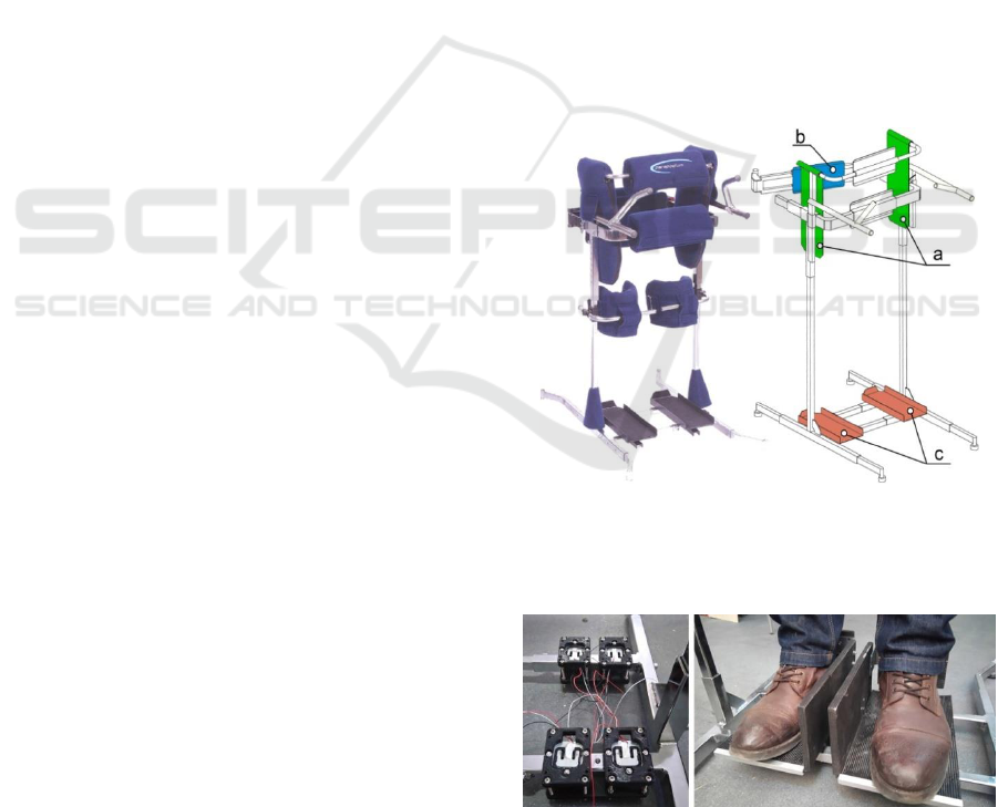
A static standing frame PJMS 180 (Figure.1, left) has
been chosen as a platform to be modified in order to
fit the sensors. It is a commercially available stander,
already designed to be safe for the patient. It’s crucial
that the position/length of each component of the
stander is easily adjusted, thus adapting the device to
our needs with a reasonable amount of work.
The position of the two independently mounted
platforms on which the patient stands can be shifted
in coronal plane. Pillows on the sides of the stander,
as well as the one in the front and in the rear hold the
patient in the upright standing position. Those can be
raised or lowered depending on the height of the
patient. The distance between them can also be
adjusted. Two cups straightening the knees that were
originally installed in the device have been removed
so that the patient is able to lift the leg and bend the
knee. In case the patient has little or no control over
the extensor muscles of the leg, the cups may be
replaced with a rubber band so that the legs return to
the straightened position.
The measurement of the applied force is done by
load cells mounted in the frame. Each of the
highlighted surfaces on the left in Figure 1 is capable
of sensing the force acting perpendicularly to the
surface. Load cells used in the pillows (Figure 1a and
Figure 1b) are beam type load cells NA27-005. Their
measurement range is wide enough so that a person
weighing 90 kg and with a height between 155 and
185 cm may lean on any pillow and the reading will
be adequate to the leaning force. In order to measure
the body weight distribution between right and left
leg, load cells YZC-161 are used (Figure 2, left).
Their advantage is that they have very low profile
(12mm) while being able to measure and withstand
significant loads (up to 40 kg each).
Both left and right standing platform is equipped
with a vertical barrier on the inside edge of the
platform (Figure 2, right). This is due to the fact that
the patient with whom we were working had
problems with putting his feet back on the platform
after raising them. A 10 cm barrier between his feet is
enough to manage this problem.
The device is designed targeting both private
customers and medical centres that focus on the
therapy of CP patients. With all that in mind the
design allows the device to be lightweight and easy
to move in a house or at a gym, so that it can be placed
in a convenient place. The weight and size of the
device allows carrying it around with minimal effort.
Figure 1: Static stander in a basic version (left), sensing
surfaces after mounting sensors (right); a) green - two side
pillows surfaces; b) blue - rear pillow surface; c) red -
sensors under the feet.
Figure 2: Four YZC-161 load cells bundled to measure
weight of the patient (left); standing platforms mounted on
the top of the load cells (right).
BIODEVICES 2019 - 12th International Conference on Biomedical Electronics and Devices
28
Shifting body weight from one leg to another
implies shifting the position of the hips to the sides as
well. For this reason the distance between each of the
side pillows and the patient’s hips remains
approximately 3 cm. This distance was chosen after
trial tests. We noticed it was still enough for the
patient to feel comfortable and safe, knowing that he
can lean on the side pillow, while it was enough for
him to shift the body weight as well. Lack of constant
pressure between the patient's body and the side
pillows of the stander requires more physical strength
from the patient, therefore it has to be adjusted
specifically for the patient.
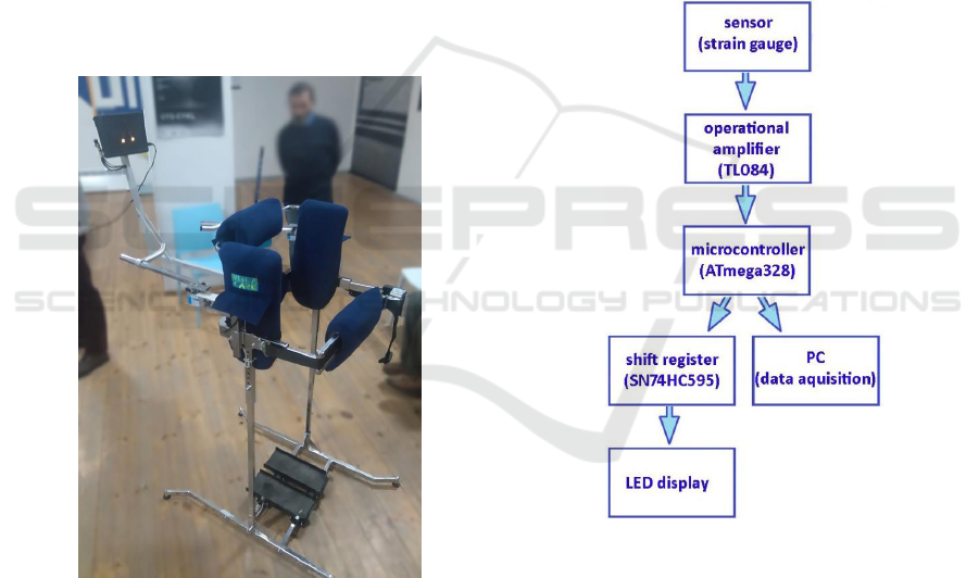
The complete device, prepared for tests is
presented in Figure 3 with LED (Light Emitting
Diode) display mounted in front of the patient. Since
no one is in the device only two LEDs indicating null
weight applied to the right and left standing platforms
are illuminated. In this setup, the two holding bars in
front of the patient are present but during later tests
they were removed.
Figure 3: A photograph of the JStep platform with LED
display mounted in front of the modified stander.
2.2 Sensory System and Data
Acquisition Module
Each load cell mounted in the pillows is a separate
measuring cell. Load cells mounted under the
standing platforms are placed in bundles of four and
create two groups of Wheatstone half-bridges
configuration on each of the two platforms. This gives
possibility to measure body weight distribution bet
ween left and right leg.
The signal flow diagram is presented in Figure 4.
The entire device is powered only through USB 2.0
5V, therefore the signal from load cells has to be
amplified with low voltage analogue amplifiers
TL084. A central unit ATmega328 controller is
equipped with a built-in analogue-digital converter
with a resolution of 10-bit, and six channels. In order
to light up adequate number of LED on a display in
front of the patient, shift registers are used. Fast
switch ing between illuminated LEDs gives the
possibility to control nine independent LEDs with one
output from the ATmega unit. Collected data includes
amount of time spent in order to execute an exercise
as well as amount of force applied to the device by
the patient. All together is transmitted through UART
via USB to a personal computer with a 10 Hz
frequency.
Figure 4: A diagram of information flow of the force
applied to the device.
2.3 LED Display and Control Panel
Significant difficulties in reading and understanding
complex information by patients with vestibular
system damage within Cerebral Palsy in cerebellum
(Ojoga and Marinescu, 2013) implies that the
information about the forces applied to the device has
to be shown in a simple and informative way. A
numerical display with values changing in respect to
the force applied to the device was tested, but the
patient could not understand the readouts during the
A New Rehabilitation Device for Balance Impaired Individuals
29
exercises, thus there was no biofeedback. Any results
from these tests are inconclusive.
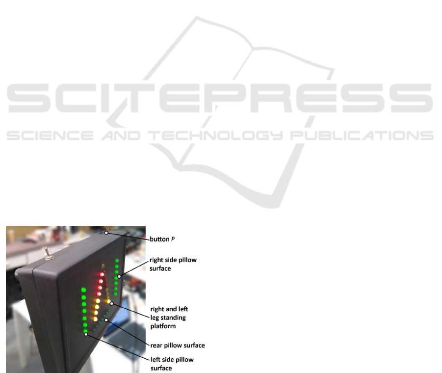
Authors decided, that a solution to this problem
would be a LED display (shown in Figure 5)
composed of five bars, each representing one sensing
surface (presented earlier in the Figure 1 on the right).
Applying force to a sensing surface results in lighting
up a correlated LED bar. The more force is applied,
the more LEDs in the bar are illuminated. Force
applied to the side and rear pillows is shown in green
bars on the sides and at the bottom of the display.
Body weight distribution between left and right leg is
shown as two yellow-red tapering bars. When the
force is equally distributed all yellow LEDs are
illuminated. As soon as the weight is transferred to
one of the sides, more LEDs on this side is
illuminated, whereas the bar showing readings from
the opposite side is diminishing.
Such a display setting allows to understand the body
weight distribution at a glimpse of an eye, which
allows to see the reactions between the patient and the
device. Moreover it is very easy to set a goal for an
exercise and the patient clearly sees if he is succeed-
ing or not. This lets the patient put more attention to
execute the task rather than focusing on reading the
information from the display.
The simplicity of the display is achieved at the
expense of readings resolution. As it is mentioned by
a number of authors (Matyja, 2012)(Matyja and
Domagalska, 1998)(Batra et al., 2011) the asymmetry
of movements and reflexes is crucial in the
examination of motor skills. For that reason a system
that visualizes movement asymmetry rather than
precise forces applied to the device by the patient
gives better feedback information and is more
informative. Independent to what is shown to the
patient on the display, raw data is sent directly to the
PC (Personal Computer) for further analysis.
Figure 5: LED display mounted in front of the patient with
LED bars and button "P" indicated.
2.4 Sensor Calibration
The spasticity of some muscle groups in CP can cause
the inability to equalise the pressure of left and right
leg on the base. It does not, however conclude for the
inability of maintaining stability. The device allows
calibrating the pressure range for sensing surfaces, so
that it is tailored to the patient and their abilities.
The microcontroller used in the control system
enables adjustment of the device performance to the
patients of various weight and independently of how
much force they apply to the device when leaning on
the side or rear pillows. This feature has been
achieved by implementing a sensor calibration.
The calibration is based on measuring maximum
force applicable by the patient to the specific sensing
surface and scaling the range of the readings
accordingly. The result is, that the first LED and all
LEDs up to the last one of a selected bar on the
display are illuminated when minimum and
maximum force is applied respectively.
Each time the device is switched on, an average
reading during first three seconds is considered a null
force reading for each sensor. During that time the
patient cannot be in the device. The system enters the
operational mode after three seconds and the patient
may enter the device.
At this point the patient is asked to apply as much
force to this sensing surface as he is capable. The
system picks maximum value read during that time
and sets it as the maximum value readable for this
sensor. This information is mapped to eight levels, so
that the LED bar can be lit properly. Afterwards the
system goes back to operational mode and in order to
calibrate another sensor, this procedure has to be
repeated. The presented procedure does not influence
readouts sent to PC via USB. The calibration refers
only to the LED display resolution and range of
signals.
3 CASE REPORT
The device has been designed and built in close
cooperation with a patient and his family. The patient
was given the device to test it for the duration of six
weeks. During this time he was asked to work with
the assignments and complete each of them every
day. The two assignments are discussed in the
3.2 Subsection. He was also asked to carry out the
calibration procedure for null weight and maximum
weight for all the sensors each day before he did the
assignments.
BIODEVICES 2019 - 12th International Conference on Biomedical Electronics and Devices
30

3.1 Subject
The patient is a 16 y.o. boy with Cerebral Palsy in the
cerebellum diagnosed when he was 20 months old.
Based on MRI tests his palsy affected multiple areas
of his brain: extrapyramidal nerves in his brain stem,
cranial nerves, the diencephalon and the pyramidal
nerve system of cortex. More precise examination is
presented in a case study (Koczyk, 2015) which
discusses EEG, MNRI and BAEP tests results. The
patient is classified with GMFCS in between level IV
and level V. His motor abilities allow him to sit and
keep the torso upright while sitting. He is also capable
of keeping his head upright and execute reaching
tasks although dysmetria, tremor and dyssynergia are
evident. He has strong astigmatism and difficulties in
controlling the eyes movements when tired.
The patient moves around his home on all fours.
This is the only way he can translocate from one place
to another in a safe environment on his own. Outside
his home he is able to move in his wheelchair but only
with an assistance. He is unable to stand still without
any support but he can hold on to furniture and rise as
well as stand holding on to it. Making steps is
challenging for the patient even when he is using
external support. An assistant is necessary to walk
him around the house but then the patient leans on the
assistant giving him full control over the equilibrium.
Due to the spasticity of his legs' rear muscles e.g.
plantar flexion is present permanently. Hence, the
patient struggles to maintain an upright standing
position because he has to flex the knees, keep his
weight on the toes and rotate his hips backwards
achieving anterior pelvic tilt. The result of such a
posture is that the patient does not bring his hips in
contact with the front pillow of a stander.
3.2 Testing Procedure and Exercises
Scenarios
The device was located in a room, where the patient
could easily enter the stander. In case the patient
requires assistance, the assistant helps him walking
into the device, locking the rear clasp and turning on
the device. The patient performs twice two exercise
scenarios each day, what results in approximately
30 minutes of standing in the device daily. In case the
patient is sick or unable to perform his duty that day
he is asked to complete his task the other day
additionally to the scheduled exercises for that day.
Exercise scenarios:
1. Illuminate specific number of LEDs related to the
body weight distribution – goal is to shift the weight
in order to reach a given number of LEDs randomly
chosen from two tapering LED bars as discussed in
Subsection 2.3. In order to complete the exercise the
given LED has to be kept illuminated for five
consecutive seconds. The patient has 120 seconds to
succeed. Otherwise the system automatically ends
this round of an exercise. The exercise consists of two
rounds.
2.Illuminate specific number of LEDs related to the
body weight distribution while refraining from
illuminating the LEDs related to the side or rear
pillows – the patient has to execute the same
algorithm as in the first exercise but this time leaning
on the device results in lighting up the green bars on
the LED display while the LED bars related to the
standing platform are switched off. The patient is
obliged then to diminish the pressure on the side
pillows and find the correct weight distribution again
During the exercises the patient was asked not to
grasp the stander with his hands. To facilitate that, he
was given two cylindrical objects to hold.
For the sake of completing the second exercise a
feasible threshold of force applied to the pillows has
to be set, otherwise a person with stability deficits
will not be able to finalize this task. After some trial
tests the threshold value was set as 40% of the
maximum force applicable to the pillows for this
particular patient. This is in line with a very important
aspect of the gamification, which is the win-lose ratio.
In order to keep the patient actively involved in the
game, hence in the rehabilitation process, a game
designer has to maintain the game challenging for the
patient but at the same time plausible to succeed.
All the tests and exercises were performed in a
room temperature varying between 21C and 30C.
To achieve results independent from the temperature
variations, load cells readouts were verified in respect
to the temperature changes. This was done thanks to
the sensors' null calibration feature, which is
essentially the readout of a non-loaded sensor. This
data was collected from each day the device was used
and stacked with room temperature changes in order
to avoid any temperature influence onto the results.
3.3 Results and Discussion
During six week time period the patient performed
the first exercise scenario 154 times and the second
exercise scenario 113 times. It took him 23 days to
complete all these exercises which was the result of
patient's frequent respiratory infections. It was
notable that after each break (the longest was five
days in a row) he struggled with achieving a correct
body weight distribution.
All the results gathered include: date and time;
current number of exercise (1 or 2); current round
A New Rehabilitation Device for Balance Impaired Individuals
31
number (1 or 2); current LED number illuminated as
a target for this exercise, which together with the
round number refers to the requested body weight
distribution (1 through 8); amount of time spent on
completing the exercise (in milliseconds); amount of
time spent with a correct body weight distribution (in
milliseconds); and for the second exercise, the
amount of time the patient applied force to the pillows
higher than the threshold (in milliseconds).
Data acquired during tests is divided based on the
side to which the patient had to transfer the body
weight as well as the amount of body weight applied
to the particular side. There are four weight levels:
63% or less, 63 − 75%, 75 − 88% and 88 − 100% of
body weight transferred to a particular leg. Such a
division is done in order to identify if the patient has
a problem with acquiring a specific body weight
distribution.
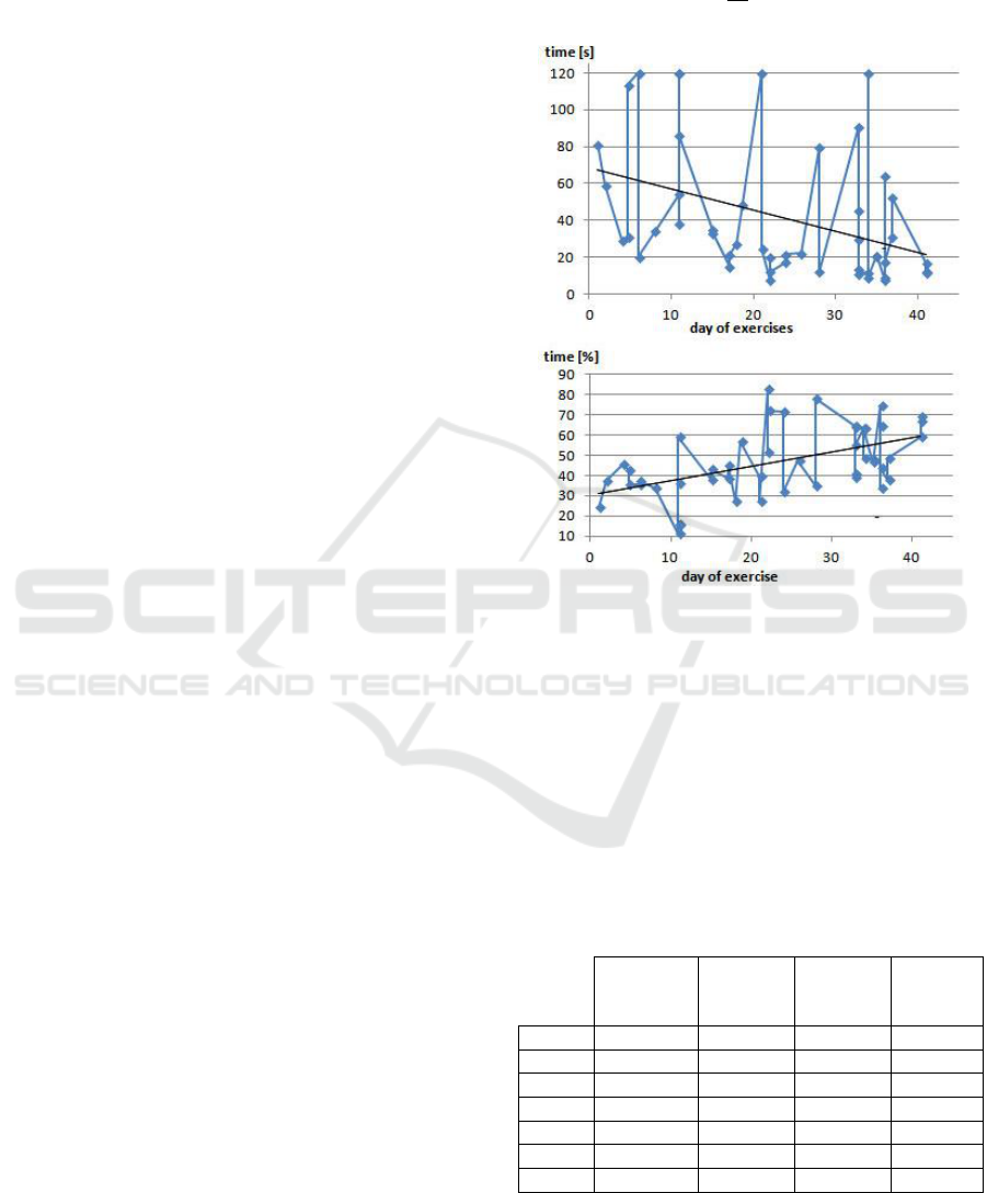
The first quality criteria for both of the exercises
is T
a
which is the amount of time necessary for the
patient to achieve and maintain the desired body
weight distribution for five consecutive seconds. The
exemplary results showing T
a
gathered for exercise 1,
when the task was to keep the body weight evenly
distributed between left and right leg with maximum
63% of the weight on one leg in a timespan of 42 days
is shown in Figure 7, top. A trend function:
y=-1.15+68 with coefficient of determination
R
2
=0.15 is embedded into the plot.
For both legs and all four body weight distribution
levels, the trend function during the six weeks
training time resulted in a negative slope constant
which is presented in Table 1 as a linear trend
function of subsequent plots. Additionally, the
percentage of decrease of time necessary to complete
the exercise ΔT
a
for both legs combined based on a
trend function is also included. A significant decrease
of time necessary to succeed in this task as the
training proceeded can clearly be noticed. The
activity which took approximately 70 seconds, after 6
weeks of training was more often achieved in only 20
seconds. Also, at first glance, an improvement in case
of 63 − 75% level is least impressive, but in this case
T
a
was the lowest out of all four load cases which is
further shown in Table 2. This shows, that for tasks
which are generally easier for the patient, the
improvement is less notable.
The second quality criteria for both of the
exercises is T
s
which is the amount of time during
which the desired body weight distribution was
achieved but not necessarily maintained for
consecutive five seconds. The T
s
in its nominal value
does not include that the overall time of completing
the task may change reducing possibility to achieve
higher T
s
values. Hence, T
s
is further considered a
percentage value of a T
a
time, where:
𝑇
𝑠%
=
𝑇
𝑠
𝑇
𝑎
∙ 100%
(1)
Figure 6: On the top - time necessary to complete the task
in exercise 1 - T
a
; on the bottom - percentage of time
necessary to complete the exercise during which patient
achieved desired body weight distribution but not
necessarily maintained it for consecutive 5 seconds - T
s%
.
Data presented for case where the patient's weight had to be
distributed evenly with up to 63% of weight on one leg.
Table 1: Linear trend function y=ax+b of T
a
and T
s%
in
function of days (t) the exercises were performed for
subsequent body weight distribution levels. LL stands for
the left leg, RL stands for the right leg, and TO stands for
both legs combined. Additionally, ΔT
a
is a percentage
decrease of time necessary to complete the exercise for both
legs combined based on a trend function T
a
(TO).
100-88% of
weight on
one leg
88-75% of
weight on
one leg
75-63% of
weight on
one leg
up to 63%
of weight
on one leg
T
a
(LL)
-0.37t+31
-2.09t+81
-0.44t+44
-0.99t+51
T
a
(RL)
-1.89t+129
-2.0t+89
-0.1t+35
-1.2t+79
T
a
(TO)
-2.15t+113
-2.0t+87
-0.27t+39
-1.15t+68
T
s%
(LL)
-1.91t+105
0.91t+25
0.06t+48
0.74t+33
T
s%
(RL)
0.66t+8.95
1.3t+24
0.17t+49
0.68t+27
T
s%
(TO)
0.52t+23
1.14t+25
0.1t+49
0.71t+30
ΔT
a
[%]
78
85
28
68
An exemplary result for T
s%
is presented in Figure 7,
bottom, where data was gathered for the first exercise
with body weight evenly distributed between left and
BIODEVICES 2019 - 12th International Conference on Biomedical Electronics and Devices
32
right leg with maximum 63% of the body weight on
one leg in a timespan of 42 days. Here the trend
function y=0.71+30 with coefficient of
determination R
2
=0.26 is embedded into the plot.
Calculated trend functions of T
s%
for each leg
separately as well as for both legs combined and for
all of the four body weight distribution levels are
presented in Table 1.
In most cases T
s%
rises as the patient progresses
with the training with an exception for 88 − 100% of
body weight transferred to the left leg. This could be
explained by a very low T
a
values for this load case
(fastest was 11 seconds and slowest was 25 seconds).
Having in mind, that for 5 seconds patient has to
maintain the correct balance anyway, achieving better
results becomes very challenging. Another aspect is
that T
s%
is inversely proportional to the T
a
values.
This implies that decreasing T
a
readouts with
consecutive training days (what evidently occur) will
always result in T
s%
getting higher. Therefore, even
though T
s%
shows improvement over time, changes of
nominal time spent on standing with proper body
weight distribution in most cases were found not to
have an apparent trend nor change significantly.
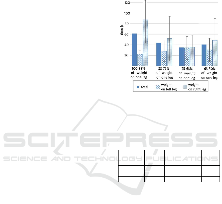
The combined results of T
a
from six-weeks
training period are calculated in order to achieve an
overall view of patient's abilities. Mean time value T
a
is presented in Figure 8 and Table 2 for each body
weight distribution level separately what provides
information about posture dissymmetry.
It is notable, that tasks involving shifting body
weight to the right leg are much more difficult for the
patient. Also, the more weight is to be transferred to
the right leg, the more difficult the task becomes.
Standard deviations of up to SD=22 for the body
weight shifted mainly onto the left leg and up to
SD=43 for the body weight shifted mainly onto the
right leg are the result of frequent failures in body
weight distribution task in 120 seconds time limit. For
the task of transferring body weight onto the left leg
patient did not succeeded only twice (for 87 times the
task was assigned) whereas in the case of transferring
body weight onto the right leg it happened 11 times
throughout all 67 times the task was assigned.
Observation of the patient while he was in training
though revealed that most of the times he did not
succeeded happened when he was distracted by a
nearby discussion or was anxious to do something
else in the time he was exercising. It is disputable
therefore if a drop-out ratio should be considered as
an important parameter for this study.
Restriction inflicted in the second exercise by the
presence of side and rear pillows significantly
extended the time necessary for the patient to achieve
and maintain the desired body weight distribution for
Figure 7: Mean time value 𝑇
𝑎
̅
̅
̅
̅
necessary to complete the
task in exercise 1 - data divided for four levels of body
weight distribution and presented for each leg separately as
well as for both legs combined (total).
Table 2: Data referring time value 𝑇
𝑎
̅
̅
̅
̅
necessary to complete
the task in exercise 1 presented for both legs in total as well
as for the left and right leg separately in all four body weight
distribution cases. LL stands for the left leg and RL stands
for the right leg.
Percentage
of weight
on one leg:
100-88%
88-75%
75-63%
63-50%
𝑇
𝑎
̅
̅
̅
total [s]
61
44
35
41
𝑇
𝑎
̅
̅
̅
(LL) [s]
87
52
36
49
𝑇
𝑎
̅
̅
̅
(RL) [s]
22
28
34
30
five consecutive seconds (T
a
). Mean time value 𝑇
𝑎
̅
̅
̅
is
presented in Figure 9 as well as in the Table 3. Here
the differences in shifting body weight over left or
right leg are not so obvious and improvement in 𝑇
𝑎
̅
̅
̅
is
only notable in respect to amount of body weight
shifted to the side. This suggests, that it was more
difficult for the patient to stand without leaning on the
pillows than it was to shift the body weight to a
correct position.
The task of transferring the body weight properly
to the left and right leg in the second exercise was
assigned 57 and 56 times respectively. In case of the
left leg the patient did not manage to achieve success
in the 120 seconds time limit six times and for the
right leg it was eight times. This resulted in standard
deviations of 𝑇
𝑎
̅
̅
̅
up to SD=38 for the left leg and up to
SD=54 for the right leg results. Again, the drop-out
Case were mostly inflicted by external disturbances.
A New Rehabilitation Device for Balance Impaired Individuals
33
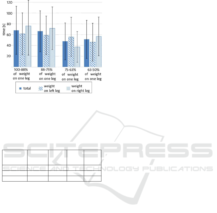
Figure 8: Mean time value 𝑇
𝑎
̅
̅
̅
̅
necessary to complete the
task in exercise 2 - data divided for four levels of body
weight distribution and presented for each leg separately as
well as for both legs combined (total).
Table 3: Data referring time value 𝑇
𝑎
̅
̅
̅
̅
necessary to complete
the task in exercise 2 presented for both legs in total as well
as for the left and right leg separately in all four body weight
distribution cases. LL stands for the left leg and RL stands
for the right leg.
Percentage
of weight
on one leg:
100-88%
88-75%
75-63%
63-50%
𝑇
𝑎
̅
̅
̅
total [s]
68
66
48
51
𝑇
𝑎
̅
̅
̅
(LL) [s]
76
72
37
57
𝑇
𝑎
̅
̅
̅
(RL) [s]
61
59
56
46
The results in case of the second exercise are
much more consistent and show very similar 𝑇
𝑎
̅
̅
̅
values for all four cases where the weight had to be
shifted onto the left leg. We noticed also very little
improvement of T
a
and T
s%
parameters over the six-
weeks training time in case of second exercise. This
is probably due to a very high difficulty the patient
had with the task of shifting the body weight while
simultaneously caring not to lean on the device.
4 CONCLUSIONS
We have presented a new rehabilitation device for
people with stability deficits. Discussed assisting
device ameliorates keeping the equilibrium by
training the body weight shifting in coronal plane
while visualizing patient's current body weight
distribution and forces inflicted onto the pillows
keeping him in an upright standing position. The
device is designed to be used by the people who may
not necessarily be able to keep the upright standing
position on their own but have muscle strength
sufficient to maintain an upright position with use of
a stander.
A set of exercises is proposed in order to train the
stability with use of the device. They involve shifting
patient's body weight so that it matches requested
body weight distribution while avoiding leaning onto
the side and rear pillows of the stander.
Forces inflicted onto the device are shown in form
of LEDs being illuminated as the patient applies more
force to the device or shifts the body weight. Such
functionality gives physiotherapists real time
information about body weight distribution while the
patient is performing exercises in an erect position.
Moreover it provides a wider knowledge about the
compensation the patient may need in order to keep
the upright standing position. It is also considered that
the device may play a significant role in an evaluation
process of patients' stability. Performing proposed
exercises allows to estimate the capabilities of the
patient.
For the patient, on the other hand, important
aspect of using the device is that, with the instant
biofeedback about the body weight distribution, the
patient may adjust his position by himself. This can
be done even if the person's reflexes are stunted or the
nervous system doesn’t work correctly.
Thanks to the presented calibration process the
measurement system is versatile making the device
suitable for work with patients of any weight or
height.
The device was tested with an Ataxic Cerebral
Palsy patient during a six-week time period. During
this time the patient performed 267 times the
exercises described. It means the patient spent
approximately 30 hours in the device safely standing
and performing exercises, what is already a great
success. Detailed results given by the system were
discussed with physiotherapists and several
conclusions were drawn:
1. The patient tends to grasp the stander. This was
notable mainly when the patient tried to produce
dynamic movements with relatively high
acceleration. Holding to a steady stander gave the
patient more confidence in movements and requested
tasks were performed faster. If the aim is to induce a
correct muscle tonus while in erect position, then
body dynamics should be drawn from body mobility
and control rather than external support.
2. The randomness of body weight distribution
requests should be introduced after repetitive
movements requests. This is due to the fact, that the
BIODEVICES 2019 - 12th International Conference on Biomedical Electronics and Devices
34

integrity of reflexes of ataxic patients is not
developed properly and they struggle to control their
body. Giving them a task, to shift the body weight and
ask to pay attention to leaning on the device is far too
much for them at the beginning of the training.
3. Physiotherapists struggled with too much
information from the system. It is considered for
future works therefore to limit the possible body
weight levels to: left, centre, and right, rather than
eight separate levels.
In future works we would like to develop more
sophisticated environment, where the patient is
motivated to pursue best results based on gratification
system embedded in a computer game.
ACKNOWLEDGEMENTS
The authors would like to express their gratitude and
thanks to Jan Koczyk and his family for continuous
support of this project and involvement in testing.
Valuable assistance during the project realization was
provided by physiotherapist Katarzyna Sęk. Further,
we thank Barbara Karlik for careful reading of the
manuscript and language suggestions.
REFERENCES
Batra, M., Sharma, D.V.P., Batra, D.V., Malik, D.G.K.,
Pandey, D.R.M., 2011. Postural Reactions: An
Elementary Unit for Development of Motor Control.
Disabil. CBR Incl. Dev. 22, 134–137.
Błaszczyk, J.W., 2004. Biomechanika Kliniczna:
podręcznik dla studentów medycyny i fizjoterapii.
Wydawnictwo Lekarskie PZWL, Warszawa.
Drużbicki, M., Przysada, G., Rykała, J., Podgórska, J.,
Guzik, A., Kołodziej, K., 2013. Evaluation of the
effectiveness of selected scales and methods used in the
assessment of gait and balance after a cerebral stroke.
Przegląd Med. Uniw. Rzesz. i Nar. Inst. Leków w
Warszawie.
Gałęcki, S., Walasik, M., Rokicki, R., Sikorska, K.,
Dudkiewicz, Z., 2013. Effectiveness of rehabilitation
and exercises on static-dynamic parapodium with
biofeedback in relation to body balance in patients after
ischaemic stroke. Kwart. Ortopedyczny 2013, 314–325.
Gilfoyle, E.M., Grady, A.P., Moore, J.C., 1990. Children
adapt : a theory of sensorimotor-sensory development.
Slack Inc.
Horak, F.B., 2006. Postural orientation and equilibrium:
What do we need to know about neural control of
balance to prevent falls? In: Age and Ageing. pp. ii7-
ii11.
Hurło, L., Kowalski, M.I., 2003. Zaburzenia postawy ciała
w wieku rozwojowym. Uniwersytet Warmińsko-
Mazurski w Olsztynie, Olsztyn.
Koczyk, M., 2015. Case study of Janek: MNRI for a Child
with Severe Cerbellum Damage. Reflexes Portal to
Neurodev. Learning., Svetlana Masgutova Educational
Institute, A Collect. Work. 271–280.
Kuczyński, K., Podbielska, M., Bieć, D., Paluszak, A.,
Kręcisz, K., 2012. Podstawy oceny równowagi ciała:
czyli co , w jaki sposób i dlaczego powinniśmy
mierzyć? Acta Bio-Optica Inform. Medica. Inżynieria
Biomed. 18, 243–249.
Livingstone, R., Paleg, G., 2016. Measuring Outcomes for
Children with Cerebral Palsy Who Use Gait Trainers.
Technologies 4, 22.
Matjacić, Z., Hesse, S., Sinkjaer, T., 2003.
BalanceReTrainer: a new standing-balance training
apparatus and methods applied to a chronic hemiparetic
subject with a neglect syndrome. NeuroRehabilitation
18, 251–259.
Matyja, M., 2012. Neurorozwojowa analiza wad postawy
ciała u dzieci i młodzieży. Wydawnictwo Akademii
Wychowania Fizycznego w Katowicach, Katowice.
Matyja, M., Domagalska, M., 1998. Podstawy
usprawniania neurorozwojowego według Bert i Karela
Bobathów. ląska Akademia Medyczna, Katowice.
Michalska, A., Dudek, J., Bieniek, M., Tarasow-Zych, A.,
Zawadzka, K., 2011. The application of the balance
trainer parapodium in the therapy of children with
cerebral pals. Fizjoterapia Pol. 11, 273–285.
Ojoga, F., Marinescu, S., 2013. Physical Therapy and
Rehabilitation for Ataxic Patients. Balneo Res. J. 4, 81–
84.
Paleg, G., Livingstone, R., 2015. Outcomes of gait trainer
use in home and school settings for children with motor
impairments: A systematic review. Clin. Rehabil. 29,
1077–1091.
Palisano, R., Rosenbaum, P., Bartlett, D., Livingston, M.,
Walter, S., Russell, D., Wood, E., Galuppi, B., 2007.
Gross Motor Function Classification System Expanded
and Revised. Ref. Dev Med Child Neurol 39, 214–223.
Shanahan, C.J., Boonstra, F.M.C., Cofré Lizama, L.E.,
Strik, M., Moffat, B.A., Khan, F., Kilpatrick, T.J., van
der Walt, A., Galea, M.P., Kolbe, S.C., 2018.
Technologies for Advanced Gait and Balance
Assessments in People with Multiple Sclerosis. Front.
Neurol. 8, 708.
Woollacott, M., Shumway-Cook, A., Hutchinson, S., Ciol,
M., Price, R., Kartin, D., 2005. Effect of balance
training on muscle activity used in recovery of stability
in children with cerebral palsy: A pilot study. Dev.
Med. Child Neurol. 47, 455–461.
Zafeiriou, D.I., 2004. Primitive reflexes and postural
reactions in the neurodevelopmental examination.
Pediatr. Neurol.
A New Rehabilitation Device for Balance Impaired Individuals
35
