Non-rigid Shape Registration using Curvature Information
Albane Borocco and Beatriz Marcotegui
MINES ParisTech, PSL Research University, CMM - Centre for Mathematical Morphology,
35, rue St. Honore, 77305 Fontainebleau, France
Keywords:
Non-rigid Registration, Shape Registration, High Curvature, Industrial Quality Control.
Abstract:
This paper addresses a registration problem for an industrial control application: it meets the need to registrate
a model on an image of a flexible object. We propose a non-rigid shape registration approach that deals with
a great disparity of the number of points in the model and in the manufactured object. We have developed a
method based on a classical minimization process combining a distance term and a regularization term. We
observed that, even if the control points fall on the object boundary, the registration failed on high curvature
points. In this paper we add a curvature-based term in order to improve the registration on object extremities.
We validate our approach on a real industrial application. The addition of this curvature term reduces by two
the error of the inner boundaries location on the previously problematic cases of our database.
1 INTRODUCTION
Manufacturing industry requires inspection tools for
controlling industrial processes. This control usually
relies on images of the manufactured objects and on a
prior knowledge of them. In our application the previ-
ous knowledge consists in the theoretical model in the
form of a set of boundaries of different object compo-
nents.
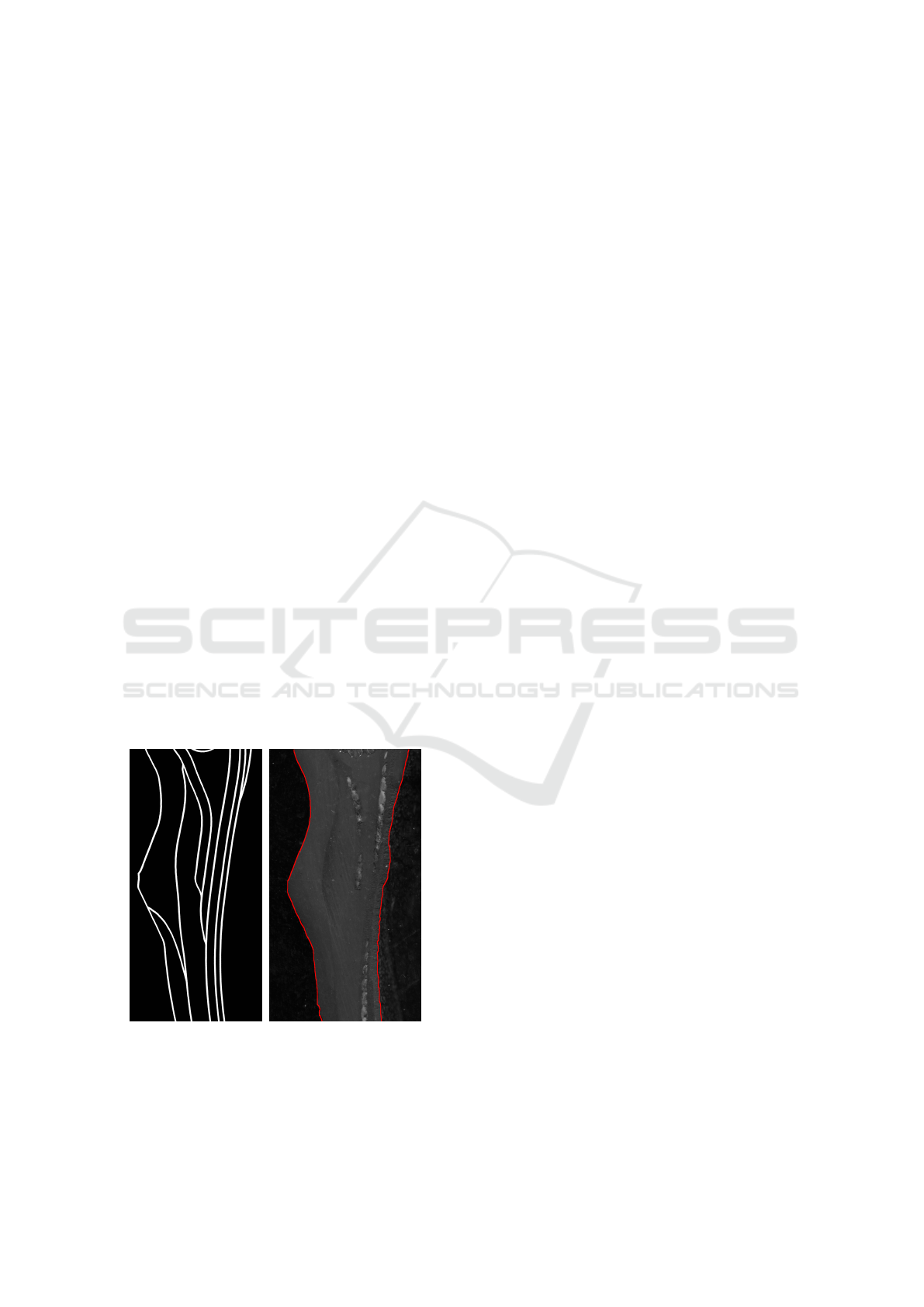
(a) model (b) manufactured object
Figure 1: Example of the data used.
Figure 1(a) shows a theoretical model from our
application. It contains the boudaries between the dif-
ferent object components. The visual appearance of
the inner parts (the textured appearance) is unknown.
Figure 1(b) shows an image of an object manufac-
tured according to this model. The segmentation of
the whole object is relatively easy. It is performed
by a marker-based watershed approach (Beucher and
Meyer, 1992). The segmentation result is overlayed in
red on figure 1(b). This step is out of the scope of this
paper. The automatic location of the inner boundaries
is much harder, as several object components have a
very similar visual appearance.
In order to control the quality of the manufac-
tured object, we need to perform the registration of
the model (2D shape) on the image of the object. This
registration relies on the external shape of the model
and the object image. The object is flexible. A non-
rigid registration method of the model on the objects
image is required.
The main contribution of this paper is the inclu-
sion of a curvature term in a non rigid registration
framework that avoids spurious deformations in high
curvature zones. The approach is validated in an in-
dustrial context.
The rest of the paper is organized as follows. Sec-
tion 2 briefly reviews the state of the art of registra-
tion methods, describes the principle of the selected
method that better fits our requirements and discuss
its performances in different situations. Section 3 pro-
poses a solution that solves the observed problems. In
section 4 we validate our solution in a industrial con-
334
Borocco, A. and Marcotegui, B.
Non-rigid Shape Registration using Curvature Information.
DOI: 10.5220/0007354903340340
In Proceedings of the 14th International Joint Conference on Computer Vision, Imaging and Computer Graphics Theory and Applications (VISIGRAPP 2019), pages 334-340
ISBN: 978-989-758-354-4
Copyright
c
2019 by SCITEPRESS – Science and Technology Publications, Lda. All rights reserved
text. Qualitative and quantitative results are given. Fi-
nally section 5 concludes this paper.
2 REGISTRATION
The registration literature is very rich and offers many
different registration methods. Interesting surveys can
be found in: (Zitova and Flusser, 2003) (Sotiras et al.,
2013). We focus on the techniques relevant to our ap-
plication. Our model contains only the boundaries of
the object’s components and the visual appearance of
the inner parts is unknown. Thus image-based regis-
tration techniques are not suitable for our application.
Also the object is made of nearly incompressible
material and suffers only large scale deformations.
Thus, the inner parts move coherently with the object
boundary. Therefore we perform a shape registration
between the 2D model and the object external bound-
ary, and then apply the computed deformation to the
entire model. The same strategy is used by Peterlik
(Peterl
´
ık et al., 2017).
Our aim is then to register the model 2D shape
to shape of the manufactured object. Because of the
flexible nature of our objects, we need a non-rigid 2D
shape registration. Many methods exist in the litera-
ture for this purpose.
Among them there are many well known methods
such as the ICP (Iterative Closest Point) method in-
troduced par Besl and McKay (Besl et al., 1992), but
even its variants later developed (Rusinkiewicz and
Levoy, 2001) (Pomerleau et al., 2013) are inappropri-
ate for cases where the sampling step is not uniform.
This is the case in our application, because the model
is discretized so that there are more points in areas
of strong curvature while the object boundary is regu-
larly sampled according to the resolution of the im-
age acquisition device. Also it is very sensitive to
the initialization step. Another widespread method
is the Coherent Point Drift (CPD) algorithm, (My-
ronenko and Song, 2010) (Myronenko et al., 2007).
It is a probabilistic method, for both rigid and non-
rigid point set registration that considers the align-
ment of two point sets as a probability density esti-
mation problem.
The method developed by Rouhani (Rouhani and
Sappa, 2012) is particularly suitable for our purpose.
Indeed, it can cope with the not even discretization
step of the model’s border. Also it exploits a quadratic
distance approximation which allows each iteration of
the algorithm to be linearly solved. Hence, the regis-
tration process has a fast convergence. Because of
those reasons we choose to use Rouhani’s method.
2.1 Principle of Rouhani’s Registration
Let us describe the Rouhani’s registration princi-
ple introduced in (Rouhani and Sappa, 2012). Let
S = {s
i
}
N
s
1
be the set of data points of the model shape
and C = {c
i
}
N
c
1
the points of the object boundary. The
registration is done by minimizing an error term in an
iterative process. This error relies on the sum of the
distance of points s
i
belonging to the model, to the
border of the object C:
SD(s
i
,C) =
d
i
d
i
− ρ
j
[(s
i
− c
j
)
T
T
j
]
2
+ [(s
i
− c
j
)
T
N
j
]
2
(1)
with s
i
the considered point belonging to the
model, c
j
the closest point to s
i
belonging to C, T
j
and N
j
, the unit tangent and outer normal at c
j
, d
i
,
the signed distance between s
i
and c
j
, ρ
j
, the curva-
ture radius at s
i
.
The use of this distance makes this registration
method it suitable for a different number of points on
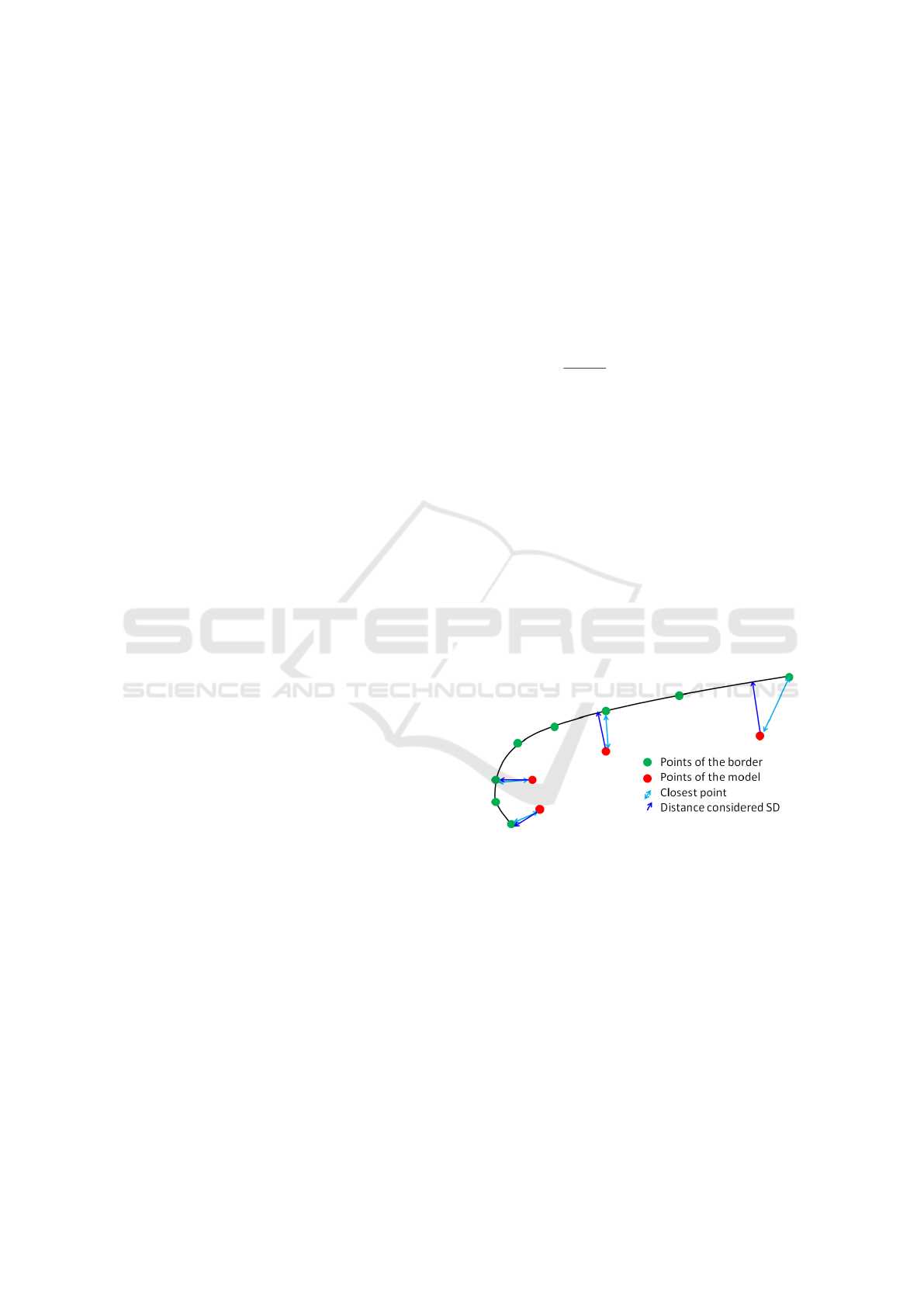
registered shapes. Figure 2 shows an illustration of
the considered distance: In low curvature zones the
considered distance is close to the normal distance to
the shape, and so the minimizing process is not af-
fected by the different number of points. Whereas
in high curvature zones, the considered distance is
equivalent to the euclidean one.
Figure 2: Illustration of the considered distance.
A squared control lattice, P, is defined and its de-
formation, L,is regularized by a global tension term ,
T (P), measured by its curvature over the whole do-
main:
T (P) =
Z Z
XY
[kL
xx
k
2
+ 2kL
xy
k
2
+ kL
yy
k
2
]dxdy (2)
with L, the vector field representing the deforma-
tion of the control lattice.
In each iteration, we optimize the deformation
field L in order to minimize the error E:
E = λT(P)+
N
s
∑
i=1
SD(L(s
i
),C) (3)
Non-rigid Shape Registration using Curvature Information
335
with L(s
i
) the position of s
i
after deformation of
the control lattice L, L(s
i
) is initialized as s
i
.
And λT (P) a regularity term in order to assure that
the local deformation is not too important.
λ represents the registration rigidity, and is auto-
matically tuned during the registration. It starts with
a high value ( λ = 10
6
), which intends to cope with
the alignment problem. Then, once the ratio of regis-
tration error between consecutive iterations is below
a given threshold, λ is divided by 10, until λ = 1.
Because of the chosen distance, the whole regis-
tration function in equation 3 is linear in terms of the
control lattice coordinates. The optimal control lattice
deformation is obtained by iterating the resolution of
a system of two linear equations. The reader is refered
to (Rouhani and Sappa, 2012) for a detailled descrip-
tion of this method.
The results obtained on our data using that method
are generally good: we observe that the external con-
tours coincide, but also, the internal ones, obtained by
the application of the deformation computed on the
external contour to the whole object, correspond to
the ones we observe in our objects, as it is shown in
figure 3.
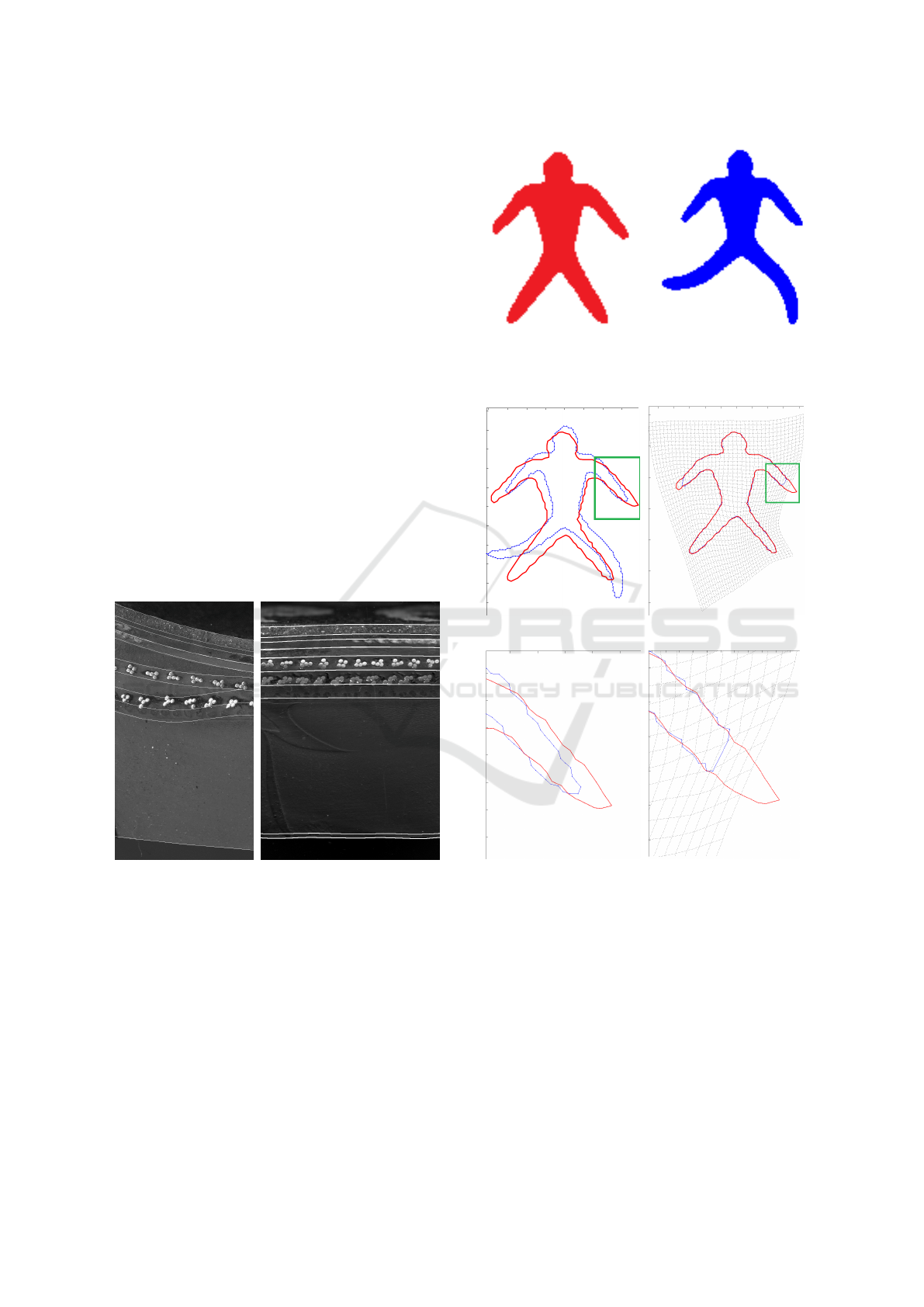
Figure 3: Good registration results on objects 6 and 16 using
Rouhnani’s method (Rouhani and Sappa, 2012).
2.2 Problems Encountered
Using that method we have performed registration
of 2D shapes, obtained from the database (Ralph,
2009).The blue shape is the model that is registered
to another instance of the object, the red shape.
Figure 5 illustrates the results obtained after
Rouhani’s registration. We can observe that every
point of the model is, after registration, projected on
the contour of the image. Based on this observation,
it may be considered as a good result. However the
(a) object: dude 0 (b) model: dude 7
Figure 4: 2D Shapes used for registration.
(a) before registration (b) after Rouhani’s registra-
tion
(c) before registration,
zoom from 5(a)
(d) after Rouhani’s regis-
tration, zoom from 5(c)
Figure 5: Registration results on 2D Shapes: dude7 and
dude0.
contours do not actually coincide: If we connect the
dots, as shown in the figure 5(c), we observe that even
if the points were moved so that they belong to the
image contour after registration, the registration fails,
specially on the dude’s arms. We can observe that
phenomenon on the figure 5(d).
This phenomenon occurs because this registration
technique tends to minimize a criterion that is only
related to the distance between the model points and
VISAPP 2019 - 14th International Conference on Computer Vision Theory and Applications
336
the contours. In the case of the dude’s arms, the point
located at the end of the arm in the model is closer to
a point located in the forearm of the image than to the
extremity. This error appears mainly in high curvature
zones.
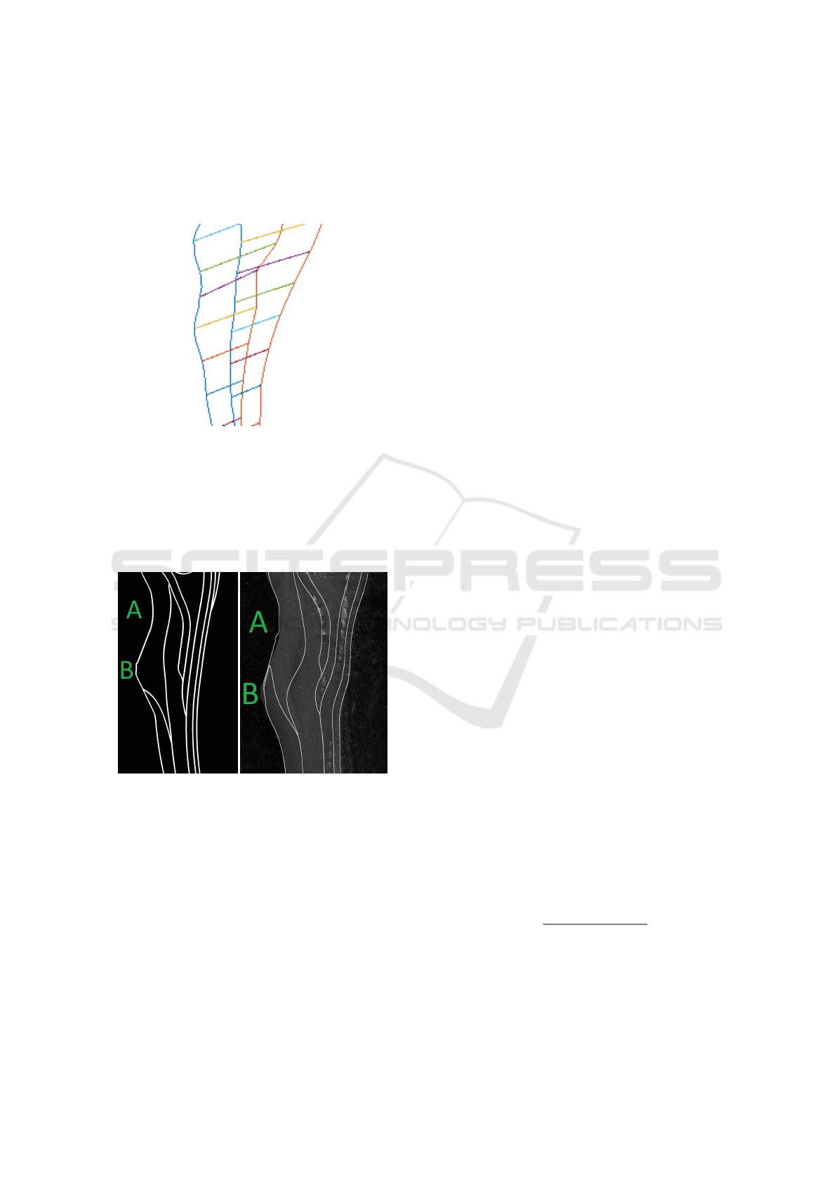
Figure 6: Mapping between model points and their location
after registration.
We also face this problem in our images. This phe-
nomenon can be observed in figure 6: the contours
coincide but there is a shift between them. The final
error achieved by the algorithm is close to zero but the
registration still fails.
(a) model (b) registration of the model
on the object
Figure 7: Registration results on object 18: the deforma-
tion due to registration introduces non-physical curvatures
on the internal contours.
This is problematic in our case because it induces
distortion in the internal contours, as shown in figure
7. The observed distortions of the internal contours
are due to a shift between the obtained registration re-
sult and the expected one. This is in our case a major
mistake: such a distortion corresponds to a stretching
in the lower area (B) and a compression in the upper
area (A), as in figure 7, inducing a curvature in the in-
ternal contours. Those two physical transformations
could not happen in the case of nearly incompressible
material, and thereby this solution is not possible.
3 PROPOSED SOLUTION
Our solution relies in the fact that the distortion be-
tween the object and its model is global. Because of
that, high curvature zones present in the model will
remain in the object.
The solution we propose is to favor the pairing of
similar high curvature points by adding a term in the
error equation (3).
This term would avoid shifts between the con-
tours, but also prevent the case where model points
belong to the object’s contour after registration but the
contours do not coincide as seen on figure 5, which
happens mainly in high curvature zones.
First we detect high curvature points on the model.
We name them the characteristic points cp. Those
characteristic points are identified using the curvature
radius. For our experiment we defined a point as high
curvature point if its curvature radius ρ
j
is the lo-
cal minimum of a zone where the curvature radius is
smaller than 50 pixels.
Then we detect high curvature points on the im-
age. By definition, high curvature points of the model
are also present in the object and no additional high
curvature points are created. Therefore we select the
same number of characteristic points N
cp
as detected
in the model, within the high curvature points in the
image.
We match each characteristic point from the
model cp
i
to the closest characteristic point of the ob-
ject C(cp
i
).
We add a term in the error equation in order to
minimize the distance between characteristic points
of similar curvature.
E = λT (P)+
N
s
∑
i=0
i/∈cp
SD(L(s
i
),C)+
∑
i∈cp
µd(L(cp
i
),C(cp
i
))
2
(4)
with cp characteristic points, cp
i
being paired
with C(cp
i
), d the distance between those points and:
µ =
k
1 + |ρ
C(cp
i
) − ρ
cp
i
|
(5)
with k, being a weight to give the curvature term
more or less impact, and ρ
cp
i
and ρ
C(cp
i
)
being respec-
tive curvature radius. In our application we observed
experimentally that variations of this parameter has a
Non-rigid Shape Registration using Curvature Information
337

low sensitivity as long as it has values between 20 and
200. We decided to use k = 50.
Then as each iteration tends to reduce the global
error, the distance between those points will decrease.
4 EXPERIMENTAL RESULTS
4.1 Database
The study we conducted was for an industrial pur-
pose: an industrial partner provided us with images
of objects and the models according to which the ob-
jects were manufactured. Our database contains 80
images of size 14000 by 8000 pixels, of objects pro-
duced according to 31 different models.
In order for us to quantify the improvement on the
problematic cases of our obtained results, images of
objects with areas of strong curvature have been an-
notated by a specialist: we have a ground truth of the
real inner frontiers of the objects corresponding to 4
different models.
The method we’ve developed aims to be deployed
in factories, it must therefore must cope with a wide
variety of objects and models.
4.2 Results
Figure 8 compares the results between Rouhani’s
original method and our proposed improvement. We
observe that after Rouhani’s registration every point
of the model is projected on the image but that the
contours do not coincide.
Using our method, as the extremities of the arms
are high curvature points, those points are well regis-
tered.
Adding this constraint on high curvature points
improves the registration: in both cases every point of
the model is, after registration, projected on the con-
tour of the image, which leads to a small error term.
But the use of high curvature points pairing allows
contours to coincide even in high curvature zones.
This method improves the registration of the
model on the object produced: not defining charac-
teristic points induces a shift between contours which
corresponds to a not physical deformation (cf. figure.
7), whereas those deformations do not occur with our
method cf. figure 9.
Figure 9 shows the performances of our method
on other problematic images. We observe on all the
objects that the inner borders are less curved using our
method in comparison with Rouhani’s method. These
(a) after Rouhani’s registra-
tion
(b) after our registration
(c) extremity of the arm af-
ter Rouhani’s registration
(d) extremity of the arm
after our registration
Figure 8: Comparison of registration results on 2D Shapes
before and after adding the curvature term.
curvatures are not present in the model before regis-
tration, they where induced by the registration and do
not correspond to any physical deformation of the ob-
ject. Therefore our registration method improves the
registration.
The quantitative evaluation of the registration is
not easy. As illustrated hereinbefore, a perfect corre-
spondence of registered points is not a guarantee of
a perfect registration. In order to quantify the qual-
ity of the registration in an objective way, we intro-
duce a distance measure between the inner frontiers
of the object annotated by an expert, and their cor-
responding frontiers registered: To each point of the
registered inner frontier is associated the distance to
the closest point in the annotated frontiers.
As the objects are not perfect, even if the registra-
tion was perfect the inner contours in the image might
not correspond with those in the model. However, a
huge average distance between the annotated and the
registered frontiers reveals a failure in the registration.
The average distance to the ground truth is signif-
VISAPP 2019 - 14th International Conference on Computer Vision Theory and Applications
338
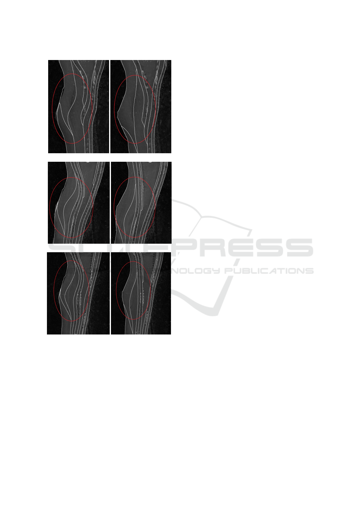
(a) object 18
(b) object 56
(c) object 75
Figure 9: Comparaison of the results obtained before (left)
and after adding the curvature term (right) on objects 18, 56
and 75.
icantly lower for our result than for Rouhani’s result.
The quantitative evaluation of the results shown in fig-
ure 9 are the following.
For object 18, shown in figure 9-a the average dis-
tance between the annotated and the registered fron-
tiers is 24.11 pixels using Rouhani’s method whereas
we obtain an average distance of 11.49 pixels using
our method. It corresponds to an improvement of 52
%.
We obtain similar results for objects 56 and 75
shown in figures 9-b and 9-c. For object 56, be-
fore adding the curvature term, the average distance
to ground truth is 22.13, whereas with that term the
average distance is 12.53, which correspond to an im-
provement of 43%. Also for object 75, before adding
the curvature term, the average distance to ground
truth is 39.78, whereas with that term the average dis-
tance is 20.94, which correspond to an improvement
of 47%.
Over all the annotated objects, the mean distance
using Rouhani’s registration is 28.9 pixels, whereas
using our method we obtain an average distance of
14.2 pixels, wich corresponds to an improvement of
51%. Those results highlight the improvement made
by our method: the average distance on all annotated
objects is divided by 2.
By the use high curvature points pairing, this
method allows us to get better results: a curvature on
the inner contours is not induced by this registration.
The registered model’s contours are closer to the ob-
ject’s without any non physical deformation induced.
This method has been applied on our whole database
and similar results have been obtained.
5 CONCLUSION
This paper presents a method to cope with registration
mistakes of 2D shapes that are common in high curva-
ture regions. It is done by first identifying and pairing
the high curvature points, then by adding a term that
favors the rapprochement of these pairs.
This method allows us to get better results that are
consistent with the physics inherent to the manufac-
tured object. It has been used in an industrial context,
and good results have been obtained on the set of im-
ages provided by the manufacturer. This method is
intended to be deployed in factories to allow a quality
control of the produced objects.
From the methodological point of view, we pro-
pose a non-rigid shape registration method, able to
handle correctly extremities registration. Our process
avoids significant deformations of objects, that can
not be seen if we verify only the contour correspon-
dence.
REFERENCES
Besl, P. J., McKay, N. D., et al. (1992). A method for reg-
istration of 3-d shapes. IEEE Transactions on pattern
analysis and machine intelligence, 14(2):239–256.
Non-rigid Shape Registration using Curvature Information
339

Beucher, S. and Meyer, F. (1992). The morphologi-
cal approach to segmentation: the watershed trans-
formation. OPTICAL ENGINEERING-NEW YORK-
MARCEL DEKKER INCORPORATED-, 34:433–481.
Myronenko, A. and Song, X. (2010). Point set registra-
tion: Coherent point drift. IEEE transactions on pat-
tern analysis and machine intelligence, 32(12):2262–
2275.
Myronenko, A., Song, X., and Carreira-Perpin
´
an, M. A.
(2007). Non-rigid point set registration: Coherent
point drift. In Advances in Neural Information Pro-
cessing Systems, pages 1009–1016.
Peterl
´
ık, I., Courtecuisse, H., Rohling, R., Abolmaesumi, P.,
Nguan, C., Cotin, S., and Salcudean, S. (2017). Fast
elastic registration of soft tissues under large deforma-
tions. Medical Image Analysis.
Pomerleau, F., Colas, F., Siegwart, R., and Magnenat, S.
(2013). Comparing ICP variants on real-world data
sets. Autonomous Robots, 34(3):133–148.
Ralph, R. (2009). Mpeg-7 core experiment ce-shape-1 test
set.
Rouhani, M. and Sappa, A. D. (2012). Non-rigid shape
registration: A single linear least squares framework.
In European Conference on Computer Vision, pages
264–277. Springer.
Rusinkiewicz, S. and Levoy, M. (2001). Efficient variants of
the ICP algorithm. In 3-D Digital Imaging and Mod-
eling, 2001. Proceedings. Third International Confer-
ence on, pages 145–152. IEEE.
Sotiras, A., Davatzikos, C., and Paragios, N. (2013). De-
formable medical image registration: A survey. IEEE
transactions on medical imaging, 32(7):1153–1190.
Zitova, B. and Flusser, J. (2003). Image registration
methods: a survey. Image and vision computing,
21(11):977–1000.
VISAPP 2019 - 14th International Conference on Computer Vision Theory and Applications
340
