
Cooperative Linker for the Distributed Control of the Barcelona
Drinking Water Network
Valeria Javalera-Rincon
1 a
, Vicenc Puig Cayuela
2 b
, Bernardo Morcego Seix
2 c
and Fernando Orduña-Cabrera
1 d
1
Advanced Systems Analysis and Ecosystem Services and Management Programs,
International Institute for Applied Systems Analysis, Schlossplatz 1, A-2361, Laxenburg, Austria
2
Advanced Control Systems Group, Universitat Politècnica de Catalunya (UPC),
Rambla Sant Nebridi, 10, 08222, Terrassa, Spain.
Keywords: Multi-Agent Systems, Large Scale Systems, Linkage of Models, Reinforcement Learning, Distributed Control,
Water Networks, Large Scale Systems.
Abstract: This work shows how a Linker agent coordinates a cooperative MAS environment to seek a global optimum.
The approach is applied to the Barcelona Drinking Water Network (DWN) administrated by AGBAR where
the main problem was to coordinate the control of three different sectors of the network. Each part has a local
controller (local agent) to solve the local water demands, but it also has to cooperate with the other agents to
satisfy the water demands of the whole network. The cooperative Linker agent implemented, learns by using
a Reinforcement Learning algorithm, called PlanningByExploration Behaviour with penalization (Javalera et
al., 2019), to converge towards an optimal (or suboptimal) value of each of the variables that connect the local
agents. For the training and simulation of the Linker agents real historical data of the Barcelona DWN
provided by AGBAR were used, as well as the data to model the distributed topology of the DWN. Moreover,
some results of the simulations of this approach in contrast with the results of a centralized Model Predictive
Controller are depicted.
1 INTRODUCTION
The Barcelona Drinking Water Network (DWN),
managed by Aguas de Barcelona, S.A. (AGBAR),
supplies drinking water to Barcelona city and the
metropolitan area. However, due to the complexity
and the computational effort required for its optimal
control, AGBAR needs for a distributed control
architecture that helps to solve the problem.
The requirement is to break down the whole water
network into smaller networks, solve them separately,
and then combine their solutions to get a global result
for the original task. However, the sub-problems (the
smaller networks) are not independent. Some
coordination between the partitions of the network is
necessary to consider the interrelationships between
them. The effort required to deal with these partitions
a
https://orcid.org/0000-0001-8743-9777
b
https://orcid.org/0000-0002-6364-6429
c
https://orcid.org/0000-0002-6944-7519
d
https://orcid.org/0000-0002-8558-0053
and their coordination can be allocated to various
processors, which constitute a distributed computing
system. In this way, distributed control is a type of
Multi-Agent System. This work presents a realistic
application of the LINKER architecture (Javalera
2016) (Javalera et al., 2019) previously called MA-
MPC architecture (Javalera et al., 2010).
One of the main problems of distributed control of
Large Scale Systems (LSS) is how these dependence
relations between sub-systems are preserved. In this
case, these relations are pipes that connect two
different control zones of the decentralized water
transport network. These connections represent
control variables, and the distributed control has to be
consistent for both zones, and the optimal value of
these variables will have to accomplish a common
goal.
560
Javalera-Rincon, V., Cayuela, V., Seix, B. and Orduña-Cabrera, F.
Cooperative Linker for the Distributed Control of the Barcelona Drinking Water Network.
DOI: 10.5220/0007349105600567
In Proceedings of the 11th International Conference on Agents and Artificial Intelligence (ICAART 2019), pages 560-567
ISBN: 978-989-758-350-6
Copyright
c
2019 by SCITEPRESS – Science and Technology Publications, Lda. All rights reserved
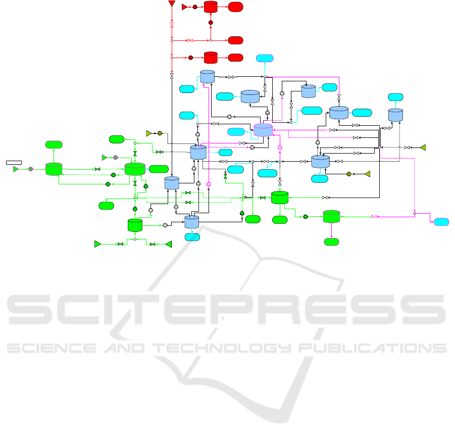
Figure 1: System diagram of the Barcelona DWN aggregate network.
The present work addresses the Distributed
Control (DC) problem by the application of the
Linker Architecture, making use of the LINKER
Methodology to implement it.
The structure of the paper is the following:
Section 2 introduces the proposed methodology.
Section 3 some details of the analysis phase of the
proposed methodology are given, while Section 4
presents the design phase. Section 5 shows the results
of the experimentation phase applied to the
considered case study. Finally, Section 6 summarizes
the main conclusions and provide future research
paths.
2 METHODOLOGY
A methodology has been developed to accurately
define and integrate the LINKER Architecture
(Javalera et al., 2010). First attempts to establish this
methodology can be found in (Javalera et al., 2010)
where a distributed MPC for a hypothetical drinking
water network was developed using the proposed
framework and compared against a centralized MPC
controller.
The LINKER methodology comprises five
phases: Analysis, Design, Experimentation,
Implementation, and Testing. The description of all
the steps of the LINKER methodology and the related
processes are described in the next sections of this
paper when applied to the Barcelona DWN case
study.
3 ANALYSIS
The purpose of the analysis phase is to define the
problem and the requirements of the system. It is the
basis of all the processes of the LINKER
methodology. In the analysis phase, there are five
steps to be defined: System description, the definition
of control objectives, the definition of functional
requirements, definition of restrictions and
considerations and definition of the partitioning. The
processes are sequential; each process is the basis for
the next one. Following the application of the
Analysis phase to the Barcelona DWN is introduced.
3.1 A System Description
The Barcelona DWN, managed by Aguas de
Barcelona, S.A. (AGBAR), not only supplies
drinking water to Barcelona city, even more, support
the metropolitan area. The sources of water are the
Ter and Llobregat rivers, which are regulated at their
head by some dams with an overall capacity of 600
cubic hectometers. Currently, there are four drinking
water treatment plants (WTP): the Abrera and Sant
c70PAL
c125PAL
CPIV
d110PAP
c110PAP
CPII
d54REL_8
d100FCE
c100FCE
VSJD_29
c100LLO
d80GAVi80CAS
85CRO
c80GAVi80CAS
c70LLO
VCA
CRE
CGIV
CCA
d115CAST
c115CAST
VCR
CB
dPLANTA
ApotLL1
CPLANTA70
CPLANTA50
d10COR
c10COR
PLANTA10
CC50
CC70
c70FLL
VZF
VCT
VT
c100BLLsud
VRM
VCO
CCO
VS
CE
VE
c130BAR
CF200
CF176
d200BLL
c200BLL
VF
d176BARsud
c176BARsud
c200BARs-c
VB
VP
VMC
d200ALT
c200ALT
VBSLL
d200BARnord
c200BARnord
d101MIR
c101MIR
CA
c100BLLcentre
VPSJ
d100BLLnord
c100BLLnord
VCOA
d70BBEsud
c70BBEsu
d
CC100
CC130
CRO
aMS
bMS
aPousB
aPousE
aPouCast
bPousB
bPousE
bPouCast
d130BAR
c140LLO
d125PAL
nAportA1_1
nAportA2_1
N70pal_2
n100LLO_3
n70LLO_4
n140LLO_5
n100BLLsud_6
n70FLL_7
n200BARsc_9
n100BLLcentre_8
VALVA45
VALVA
VALVA47
VALVA48
VALVA53
VALVA54
VALVA55
VALVA56
VALVA57
nAportT_11
ApotLL2
c176BARcentre
n176BARcentre_10
ApotA
VALVA60
VALVA61
VBMC
VALVA64
VALVA50
VALVA312
VALVA309VALVA308
ACast
bCast
CPR
CMO
d120POM
c120POM
VCON
n135SCG_11
c135SCG
u(1)
u(2)
u(3)
u(5)
u(4)
u(6)
u(7)
u(8)
u(10)
u(9)
u(11)
u(12)
u(16)
u(18)
u(14)
u(19)
u(13)
u(15)
u(20)
u(17)
u(21)
u(27)
u(22)
u(23)
u(24)
u(25)
u(26)
u(28)
u(29)
u(30)
u(31)
u(32)
u(33)
u(34)
u(35)
u(43)
u(36)
u(37)
u(38)
u(39)
u(40)
u(41)
u(47)
u(45)
u(42)
u(44)
u(49)
u(46)
u(53)
u(56)
u(48)
u(60)
u(55)
u(54)
u(57)
u(58)
u(51)
u(52)
u(50)
u(59)
u(61)
nPLANTA
x(1)
x(2)
x(9)
x(4)
x(3)
x(5)
x(8)
x(6)
x(7)
x(11)
x(10)
x(12)
x(17)
x(13)
x(14)
x(15)
x(17)
d(1)
d(2)
d(3)
d(8)
d(9)
d(5)
d(4)
d(7)
d(6)
d(10)
d(15)
d(18)
d(17)
d(14)
d(13)
d(21)
d(20)
d(19)
d(11)
d(12)
d(16)
d(22)
d(25)
d(24)
Cooperative Linker for the Distributed Control of the Barcelona Drinking Water Network
561

Joan Despí plants, which extract water from the
Llobregat river, the Cardedeu plant, which obtains
water from Ter river, and the Besòs plant, which
treats the underground flows from the aquifer of the
Besòs river. There are also several underground
sources (wells) that can provide water through
pumping stations. Those different water sources
currently offer a flow of around seven m3/s. The
water flow from each source is limited and with
varying prices of water depending on water
treatments and legal extraction canons.
The structure of the Barcelona DWN has two
layers; The upper layer, named transport network, this
layer aims to links the water treatment plants with the
reservoirs distributed all over the city. The lower
layer named distribution network, this layer is
sectored in subnetworks. Each subnetwork links a
tank with each consumer. This application case study
aims to work in the transport network. The control
system of the transport network is also organized in
two layers. The upper layer manages the global
control of the network, establishing the set-points of
the regulatory controllers at the lower layer.
Regulatory controllers are of PID type, while the
supervisory layer controller is of MPC type.
Regulatory controllers hide the network non-linear
behaviour to the supervisory controller. This fact
allows the MPC supervisory controller to use a
control-oriented linear model.
From the whole drinking water network of
Barcelona, described above, this work considers an
aggregated version of this model that is an entirely
representative version of the full network.
Aggregated means that some sectors of the network
are collected in a unique part, hence some tanks are
raised in a single representative tank and the
respective actuators in a single representative pump
or valve. This operation has been made to simplify the
complexity of the model to have a more manageable
but at the same time an essential system, in which the
control strategy of this study was applied. AGBAR
provided the demands episode of the network.
3.2 Control Objectives
Optimal control in water network deals with the
problem of generating flow control strategy from the
sources to the consumer areas to satisfy the demand
of water while optimizing performance goals such as
network safety volumes and flow control stability.
Thus, the following operational objectives should be
fulfilled by the distributed controllers by order of
priority:
Safety Term: the satisfaction of water demands
should be satisfied at any time instant, this is
guaranteed through the equality constraints of the
water mass balances at demand sectors. However,
some infeasibility avoidance mechanisms should be
introduced in the management of the tank volumes
such that this volume does not fall below a security
amount resulting in demands which cannot be
satisfied, this leads to the management of the tank
volumes above a specific security volume, which
ensures that the network can always supply the
demand flows.
Smooth Control Actions: pumps and valves
should operate smoothly to avoid large transients in
the pressurized pipes that can lead to their damage.
To obtain such smoothing effect, the MPC controller
includes in the objective function a term that
penalizes control signal variation
u(k).
Functional Requirements: the functional
requirements of this system are presented in Table I,
the control objectives are reflected in FR3, FR4, and
FR8. That means that the priority of the control is to
maintain the system inside the security levels, a
desirable reference is also considered but the priority
is FR3 and FR4. The latter one refers to a smooth
control, that means that control actions should
increase /decrease in small quantities.
3.3 Restriction and Considerations
The safety objective leads to the management of the
tank volumes above a specific security volume, which
ensures that the network can always supply the
demand flows. That is the minimum volume
restriction in tanks. A maximum safety level (to avoid
spills) should also be applied. Physical limits of
valves and pumps should be considered.
3.4 Definition of the Partitioning
For this case of study, the Barcelona DWN aggregate
network presented in Fig. 1, has been used. From this
figure, is clear that the network is comprised of 17
tanks (state variables), 61 actuators (26 pumping
stations and 35 valves), 11 nodes and 25 main sectors
of water demand (model disturbances). Nodes (of the
water network) correspond to the points where water
flows are merged or divided within the network.
Thus, the nodes represent mass balance relations and
are modelled as equality constraints related to inflows
and outflows of the nodes.
ICAART 2019 - 11th International Conference on Agents and Artificial Intelligence
562
Table 1: Functional requirements of the Barcelona DWN.
Req
No.
Name of the
requirement.
Description.
FR1
Type of
partitioning.
As defined in Fig 2.
FR2
Distributed
control.
One controller for each
partition.
FR3
Safety levels.
The tank levels should keep
between the defined limits.
FR4
Smooth control.
Control actions should
increase / decrease in small
quantities.
FR5
Avoid conflicts
and collisions.
Avoid conflicts and collisions
between sub-systems.
FR6
Satisfy
demands.
All demands have the same
priority.
FR7
FR8
Global
optimization
Follow a
reference
Seek the global optimality of
the system.
Follow a desirable reference.
Using the partitioning obtained in (Ocampo et al.,
2011), the aggregate model of the Barcelona DWN is
decomposed in three sub-systems, as depicted in Fig.
1 in different colors. The detailed information about
physical parameters and other system values are
reported in (Fambrini et al., 2009).
Table 2 collects the resultant dimensions for each
sub-system and the corresponding comparison with
the dimensions of the vectors of variables for the
entire aggregate network.
Sub-system 1: composed by tanks x
i
, i
{1, 2},
inputs u
j
, j
{1, 2, 3, 4, 5}, demands d
l
, l
{1, 2,
3}, and nodes n
q
, q
{1, 2}. It is represented in Figure
2 with red color.
Sub-system 2: composed by tanks x
i
, i
{3, 4, 5,
12, 17}, inputs u
j
, j
{7, 8, 9, 10, 11, 12, 13, 14, 15,
16, 18, 19, 25, 26, 32, 34, 40, 41, 47, 48, 56, 60},
demands d
l
, l
{4, 5, 6, 7, 15, 18, 22}, and nodes n
q
,
q
{3, 4, 7}. It is represented in Figure 2 with blue
color.
Sub-system 3: composed by tanks x
i
, i
{6, 7, 8,
9, 10, 11, 13, 14, 15, 16}, inputs u
j
, j
{6, 17, 20, 21,
22, 23, 24, 27, 28, 29, 30, 31, 33, 35, 36, 37, 38, 39,
42, 43, 44, 45, 46, 49, 50, 51, 52, 53, 54, 55, 57, 58,
59, 61}, demands d
l
, l {8, 9, 10, 11, 12, 13, 14, 16,
17, 19, 20, 21, 23, 24, 25}, and nodes n
q
, q
{5, 6, 8,
9, 10, 11}. It is represented in Figure 2 with green
colour.
Table 2: Dimension comparison between the sub-systems
and the whole network.
Elements
Subsyst
(Red)
Subsyst 2
(Green)
Subsyst 3
(Blue)
Whole
Model
Tanks
2
5
10
17
Actuators
5
22
34
61
Demands
3
7
15
25
Nodes
2
3
6
11
As it can be seen, there are inputs u
j
that are part
of more than one sub-system. In the LINKER control
architecture, these are the so-called shared variables.
Shared variables are control variables that appear in
the model of at least two sub-systems in the problem.
Their values should be consistent in the sub-systems
they appear.
The shared variables in this system (see Figure 1)
are: Sub-system 2–Sub-system 3: u18, u20, u21, u32,
u34, u40, u47, u56, u60; Sub-system 1–Sub-system 3:
u6.
4 DESIGN
The design phase comprises three processes:
definition of the LINKER architecture, the
description of the local agents and the meaning of
Linker agents. The definition of the LINKER
architecture is made first, once defined the
architecture, the definition of the local agents and
Linker can be made. The whole problem formulation
is done in this phase. This problem formulation is
based on the information gathered in the analysis
phase.
Before proceeding with the Design phase, it is
important to define what is a local agent and a Linker
Agent.
Local Agent. A local agent (or just an agent) is the
entity that is in charge of controlling one specific
partition of the system. There is one agent for each
system partition (pi). Each agent is arranged to
cooperate so that the Linker agent solves the
optimization of a common goal through a
reinforcement learning algorithm. The cooperative
behaviour of local agents is a primary issue in the
LINKER Architecture. To behave in such a
collaborative way, local agents implement three
actions:
1) They provide the data required by the Linker
agent.
2) They accept the value(s) provided by the
Linker agents of its shared variable(s).
Cooperative Linker for the Distributed Control of the Barcelona Drinking Water Network
563
3) They solve the local control problem of its
partition, adjusting the value(s) of its shared control
variable(s) in order to coordinate the solution of the
negotiation.
Linker Agent. A Linker agent is the entity that is
in charge of determining the value of one or more
shared variables between two local agents. A Linker
agent exists for every pair of local agents that have
one or more shared variables in common. Each Linker
determines the optimal value of one or more shared
variables in the set V. Each shared variable is solved
seeking a global optimum for both local agents which
are agreed to cooperate. The Linker carries out its
optimization based on the reinforcements given at
each step and on the experience obtained. This
experience is stored in a knowledge base.
4.1 Definition of the LINKER
Architecture
As it was established in Section 3.4, the system is sub-
divided in three partitions. This means that three local
agents are required for this system. A local agent
(named M
1
, M
2
and M
3
respectively) was assigned to
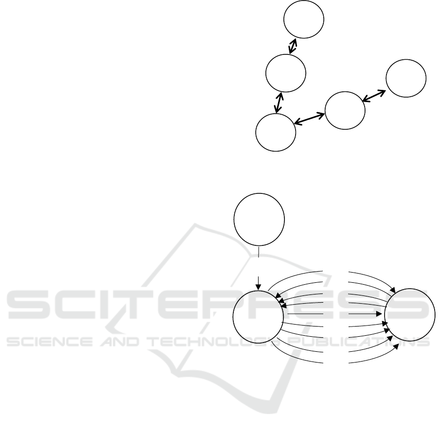
each partition (sub-system). Figure 2 shows the local
agents and the relations between them in the relation
diagram of the system.
A Linker was placed between the local agents
with shared variables between them. Two negotiator
agents were required. Figure 3 shows the resulting
general structure of the DWN system diagram.
The LINKER Architecture is defined as:
(1)
where:
M is the set of local agents, in this case defined by
(2)
N is the set of Linker, in this case defined by
(3)
P is the set of system partitions in this case defined by
(4)
Where, in this case each partition of the Barcelona
DWN (sub-system) p
i
is described by a deterministic
linear time-invariant (LTI) model that is expressed in
discrete-time as follows
(5)
(6)
where variables x, y, u and d are the state, output,
Figure 2: Relation diagram of the Barcelona aggregate
DWN.
Figure 3: General structure of the Barcelona BWN
LINKER implementation.
input and disturbance vectors of appropriate
dimensions, respectively; A, B, C and D are the state,
input, output and direct matrices, respectively. Sub-
indexes u and d refer to the type of inputs the matrices
model, either control inputs or exogenous inputs
(disturbances). Control variables are classified as
internal or shared according if they belong only to the
sub-system or are shared with other sub-systems.
W represents the set of nodes in the system, in this
case, there are nodes in all sub-systems, and they have
to be taken into account in the model of its respective
partition. For now, the set of nodes in the architecture
is defined as
W=
w
1
,w
2
, w
3
(7)
Where
and
are the sets of nodes of sub-
system 1, sub-system 2 and sub-system 3
respectively.
M
1
M
3
M
2
N
1
N
2
M
1
M
3
M
2
u
18
u
20
u
21
u
34
u
32
u
40
u
47
u
56
u
60
u
6
ICAART 2019 - 11th International Conference on Agents and Artificial Intelligence
564

V represents the set of shared variables described
above. In this case V is defined as:
V=
V
1
,V
2
, V
3
(8)
Where
and
are the sets of shared
variables of sub-system 1, sub-system 2 and sub-
system 3 respectively.
U is the set of control variables that appear in the
model of only one sub-system in the problem, these
variables are called Internal variables. In this case,
the set of internal variables is defined by:
U={U
1
,U
2
,U
3
} (9)
Where
and
are the sets of internal
variables of sub-system 1, sub-system 2 and sub-
system 3 respectively.
Finally, represents the agent platform, this
platform provides the agents with a homogenous
medium to communicate and the user with a way to
manage agents.
4.2 Definition of Local Agents
The local agents have three main elements: models, a
local controller, and a communication module. Next,
these elements will be defined for local agents M
1
, M
2
and M
3
of the system.
Plant model and disturbance model are used in
this case to implement the MPC technique of the local
agent. They are also involved in the learning process
as it will be explained later. The model of each agent
is described by a deterministic linear time-invariant
model expressed in discrete-time defined in Eq. (5)
and Eq. (6). A local MPC controller is in charge of
the control of each partition P
i
, formed by all its
internal variables, constraints, objective functions,
Prediction Horizon (H
p
) (Interval of finite future time
in which the MPC computes the predictive values by
using the model in (5) and Control Horizon (H
c
)
(Interval of finite future time in which the MPC
computes the control values by using the model in (5)
and (6)). The Communication module is the interface
that communicates and synchronizes the local agent
with the related Linker agent(s). The models are
constructed taking in to consideration the elements of
each subsystem described above and their connection
in the network of figure 1.
The calculus of states, reward and the prediction
horizon H
p
are the same for all agents and are defined
next.
s=
Hp
f=0
J
f
=
Hp
f=0
J
x
f
+
Hp
f=0
J
∆u
f
(10)
where
(11)
(12)
w
∆u
=w
x
=1 (13)
H
p
=24 (14)
4.3 Definition of the Linker
The Linker applies learning techniques in order to
find the optimal (or can we be suboptimal) values of
the shared variables of two agents, considering their
objectives with the same priority. The system is based
on the coordination and cooperation of agents, which
share data with the Linker and accept the actions
dictated by it.
The interaction between the Linker and
the agents consists in the following steps: the Linker
sends a control action to the agents at each sampling
time; the agents set that value as constraint in their
respective internal control variables and solve their
local problem associated to its partition; agents
communicate their new sate to Linker; and the Linker
calculates a reward associated to the states. This
reward is higher if the actions taken lead to a good
state for both agents. The accumulated reward is the
experience or the knowledge obtained by the Linker
through the training process. The optimization
algorithm of the negotiator agent is based on its
experience and on maximizing the reinforcements
received at every action taken in the past on similar
situations.
The Linker agents implements the
PlanningbyExploration Behaviour (PBEB), described
in depth in (Javalera, 2016) and (Javalera et al, 2019).
In the PBEB the agent explores the control action
space randomly, assigning large negative rewards to
those actions that lead to infeasible states. The
exploitation phase is made through the greedy
behaviour; see (Javalera et al, 2019) (Javalera, 2016).
The internal architecture of a Linker agent
comprises the following elements: Communication
module, knowledge base and behaviours module. The
communication module of the Linker is the analogous
of the communication module of the local agents. It
deals with the interaction between Linker and the
related agents involved in the solution of one or more
shared variables. A Q-table is a tri-dimensional
matrix that represents the knowledge related to one
particular shared variable. It maintains the Q-value
gained for each possible pair of states (of the agents
related to that shared variable) and an action.
In this way, N
1
is in charge of shared variable u
6
and N
2
is in charge of u
18
, u
20
, u
21
, u
34
, u
32
, u
40
, u
47
, u
56
and u
60
.
Cooperative Linker for the Distributed Control of the Barcelona Drinking Water Network
565
5 RESULTS
The objective of PBEB algorithm is to learn by
exploration, trying random actions but using just the
meaningful experience and penalizing the steps that
lead to unfeasible states. A training of PBEB of only
50 iterations using a negative reward of -1000 was
applied to obtain the results below. Simulations use
same random initial state and reference. The results
obtained through the proposed framework are
compared with those obtained when a centralized
MPC strategy is used. AGBAR has supplied the
model parameters and measured disturbances
(demands). Demand data correspond to consume of
drinking water of the city of Barcelona during the
year 2007.
Tank volume evolutions presented in Fig. 4 show
that using the LINKER Architecture applying PBEB
all tanks remain in the security levels and eight of ten
tanks could even follow the desirable reference. That
means that agents can solve functional requirements
FR3 and FR4 but FR8 (follow a beneficial reference)
less accurately than the centralized controller,
however, it remains close to the reference.
Table 3: Average
of the LINKER and centralized MPC
solutions
M
1
M
2
M
3
Total
Centralized
MPC
4,7837
1,7244
132,4717
138,9798
LINKER
1,4916
0
69,4476
70,9393
Table 3 shows the total of
average (the
accumulated value of all control actions) of LINKER
agents, was almost half (53.55%) of the total average
of the centralized MPC solution. That means that
The LINKER architecture provides a more
economical solution that the centralized MPC. That
also represents the improvement in requirement FR4,
smooth control actions, which is essential for the
maintenance of the actuators of the water network.
Figure 5 compares the actions applied by the
LINKER and the centralized MPC during the
simulation of figure 4.
6 CONCLUSIONS
The implementation of the LINKER Architecture and
the PBEB in the case of the Barcelona DWN leads to
a good solution where all the states are kept within
limits with a cost
of almost half (53.55%) of the
centralized solution. Ten of seventeen (the 58.8%)
Figure 4: Examples of simulations results of tank volume
evolutions. From tank x1 to x10. Blue line represents
LINKER solution and green line centralized MPC. Doted
lines are min and max volumes of tanks and red line is a
desired volume (not mandatory).
tanks of the entire system could even follow the
desirable reference (that was not mandatory). That
means that the system accomplishes the objectives of
keeping within the security levels and maintaining a
smooth control better than to track the reference. It
seems that with a more balanced partitioning the
DWN performance could still improve.
0 5 10 15 20 25
150
200
250
300
350
400
450
Agent 1 - output x1
0 5 10 15 20 25
300
400
500
600
700
800
900
1000
Agent 1 - output x2
0 5 10 15 20 25
0
500
1000
1500
2000
2500
3000
3500
4000
Agent 2 - output x3
0 5 10 15 20 25
0
500
1000
1500
2000
2500
3000
3500
Agent 2 - output x4
0 5 10 15 20 25
0
5000
10000
15000
Agent 2 - output x5
0 5 10 15 20 25
500
1000
1500
2000
2500
3000
3500
Agent 3 - output x6
0 5 10 15 20 25
1
2
3
4
5
6
7
x 10
4
Agent 3 - output x7
0 5 10 15 20 25
0
2000
4000
6000
8000
10000
12000
Agent 3 - output x8
0 5 10 15 20 25
0
1000
2000
3000
4000
5000
6000
7000
8000
Agent 3 - output x9
0 5 10 15 20 25
2000
4000
6000
8000
10000
12000
14000
16000
Agent 3 - output x10
ICAART 2019 - 11th International Conference on Agents and Artificial Intelligence
566
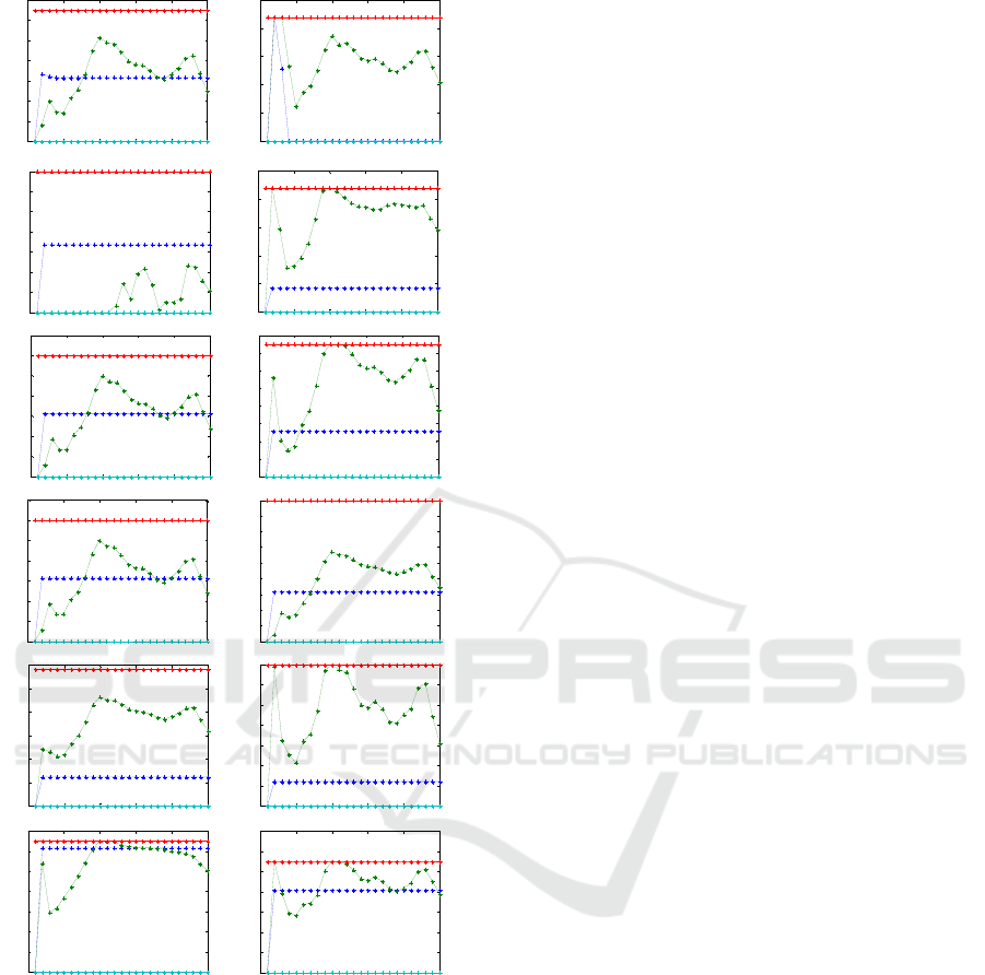
Figure 5: Evolution of some of the control actions applied
by The LINKER (blue) and the centralized MPC (green)
during simulation of figure 4. Max value (Red) and min
value (Cyan)
ACKNOWLEDGEMENTS
This work was financed by the National Council of
Science and Technology (CONACyT) and PRODEP
of Mexico.
REFERENCES
Fambrini and Ocampo-Martinez. (2009). Modelling and
decentralized Model Predictive Control of drinking
water networks. Technical Report IRI-TR-04-09.
Barcelona. Institut de Robòtica i Informàtica Industrial
(CSIC-UPC).
Javalera, V., Puig V., Morcego B. and Orduña F. (2019)
Reinforcement Learning Approach for Cooperative
Control of Multi-Agent Systems. Proceedings of the
International Conference of Agents and Artificial
Intelligence.
Javalera V. (2016). Distributed Large Scale Systems: A
Multi-Agent RL-MPCArchitecture. PhD Thesis,
Universitat Politècnica de Catalunya.
Javalera V., Morcego B. and Puig V. (2010) A multi-agent
MPC architecture for distributed large scale systems.
Valencia Spain. 2nd International Conference on
Agents and Artificial Intelligence.
Javalera V., Morcego B. and Puig V. (2010) Distributed
MPC for large scale systems using agent based
reinforcement learning. Lille France IFAC Symposium
Large Scale Systems.
Ocampo-Martinez, Barcelli D., Puig V and Bemporad A.
(2011). Hierarchical and decentralised model predictive
control of drinking water networks: Application to the
barcelona case study. IET Control Theory &
Applications.
0 5 10 15 20 25
0
0.2
0.4
0.6
0.8
1
1.2
1.4
0 5 10 15 20 25
0
0.005
0.01
0.015
0.02
0.025
0 5 10 15 20 25
0
0.005
0.01
0.015
0.02
0.025
0.03
0.035
0 5 10 15 20 25
0
0.05
0.1
0.15
0.2
0.25
0 5 10 15 20 25
0
0.2
0.4
0.6
0.8
1
1.2
1.4
0 5 10 15 20 25
0
0.2
0.4
0.6
0.8
1
1.2
1.4
1.6
0 5 10 15 20 25
0
0.2
0.4
0.6
0.8
1
1.2
1.4
0 5 10 15 20 25
0
0.2
0.4
0.6
0.8
1
1.2
1.4
1.6
1.8
0 5 10 15 20 25
0
0.5
1
1.5
2
2.5
3
0 5 10 15 20 25
0
0.05
0.1
0.15
0.2
0.25
0.3
0.35
0 5 10 15 20 25
0
0.2
0.4
0.6
0.8
1
1.2
1.4
0 5 10 15 20 25
0
0.1
0.2
0.3
0.4
0.5
0.6
0.7
Cooperative Linker for the Distributed Control of the Barcelona Drinking Water Network
567
