
A Sketch-based Interface for Real-time Control of Crowd Simulations
that Use Navigation Meshes
Luis Rene Montana Gonzalez and Steve Maddock
Department of Computer Science, University of Sheffield, Sheffield, U.K.
Keywords:
Sketch-based Interface, Crowd Simulation, Multiagent System, Navigation Mesh.
Abstract:
Controlling crowd simulations typically involves tweaking complex parameter sets to attempt to reach a de-
sired outcome, which can be unintuitive for non-technical users. This paper presents an approach to control
pedestrian simulations in real time via sketching. Most previous work has relied on grid-based navigation
to support the sketching approach, however this does not scale well for large environments. In contrast, this
paper makes use of a tiled navigation mesh (navmesh), based on the open source tool Recast, to support pedes-
trian navigation. The navmesh is updated in real time based on the user’s sketches and the simulation updates
accordingly. Users are able to create entrances/exits, barriers to block paths, flow lines to guide pedestrians,
waypoint areas, and storyboards to specify the journeys of crowd subgroups. Additionally, a timeline interface
can be used to control when simulation events occur. The effectiveness of the system is demonstrated with
a set of scenarios which make use of a 3D model of an area of a UK city centre created using data from
OpenStreetMap. This includes a comparison between the grid-based approach and our navmesh approach.
1 INTRODUCTION
Crowds are present in quotidian activities such as
walking to work, taking a train, shopping and attend-
ing a football match, and are simulated for numerous
computer applications such as in entertainment, urban
planning, safety and military training. Such crowd
simulations are commonly modelled using an agent-
based approach. However, controlling such simula-
tions can be challenging, since many parameters must
be tuned by the user. With commercial systems such
as SimWalk
1
, MassMotion
2
, Massive
3
, Legion
4
and
Exodus (Owen et al., 1996)
5
, the user needs to be
familiarised with the system and must know which
parameters to change to obtain a desired outcome.
Editing the environment can also be an issue. For in-
stance, to create an obstacle such as a barrier in Mass-
Motion, the simulation must be terminated and started
again after adding the obstacle.
This paper presents a real-time, sketch-based con-
trol approach, where non-expert users are able to in-
teract with the simulation by creating entrances/exits
to define the spawning and goal positions for pedes-
1
http://www.simwalk.com
2
http://www.oasys-software.com/products/engineering/
massmotion.html
3
http://www.massivesoftware.com/
4
http://www.legion.com/legion-software
5
http://fseg.gre.ac.uk/exodus/index.html
trians, barriers to block paths, flow lines to guide
pedestrians, waypoint areas, and storyboards to spec-
ify journeys. In addition, users can simulate events
through the day using a timeline interface. We use a
microscopic modelling approach based on agents and
a tiled navigation mesh (navmesh (Snook, 2000)) as
the navigation approach to guide the agents through
the environment.
Sketching approaches to control crowd simula-
tions have been presented before (Jin et al., 2008;
Oshita and Ogiwara, 2009; Patil et al., 2011; Hughes
et al., 2014; Gonzalez and Maddock, 2017). However,
this paper presents five novel contributions. First,
sketching is used to update a navmesh in real time,
rather than using a grid-based approach. This in-
cludes the ability to draw barriers, unlike previous
work where a list of points was used to add an obsta-
cle to a navmesh (Kallmann, 2005), which is less in-
tuitive for the user. Second, flow lines can be sketched
and the cost of traversing each flow line can be indi-
vidually changed. Third, areas can be sketched onto
an environment, similar to Hughes et al. (2014), but
with explicit control being given over the percentage
of agents visiting each (waypoint) area. Fourth, sto-
ryboards can be created to define the journeys of sub-
crowds. Last, a timeline interface can be used to con-
trol events during a simulation of a 24-hour period.
The remainder of the paper is organised as fol-
lows. Section 2 gives an overview of related work
Gonzalez, L. and Maddock, S.
A Sketch-based Interface for Real-time Control of Crowd Simulations that Use Navigation Meshes.
DOI: 10.5220/0007344200410052
In Proceedings of the 14th International Joint Conference on Computer Vision, Imaging and Computer Graphics Theory and Applications (VISIGRAPP 2019), pages 41-52
ISBN: 978-989-758-354-4
Copyright
c
2019 by SCITEPRESS – Science and Technology Publications, Lda. All r ights reserved
41

and offers a classification of the existing graphical ap-
proaches to control pedestrian simulations. Section 3
describes the implementation of the system. Section
4 presents and discusses the results. A range of sce-
narios is presented to demonstrate the effectiveness of
the system. Section 5 gives a detailed comparison be-
tween a grid-based approach and our navmesh-based
approach. Finally, Section 6 concludes the paper.
2 RELATED WORK
Agent-based modelling is the most common approach
to simulate virtual crowds. Each agent calculates
its own movement based on a set of rules or be-
haviours. Reynolds’s seminal work (Reynolds, 1987)
demonstrated how to control a bird flock with three
simple rules, and his later work (Reynolds, 1999,
2000) implemented new steering behaviours such as
seek and pursuit. Other work has shown how the
movement of agents could be determined by ‘so-
cial forces’ produced by agent-agent interaction and
agent-environment interaction (Helbing, 1991; Hel-
bing and Molnar, 1995). More recent work has shown
how psychological aspects can be taken into account
when modelling agents (Pelechano et al., 2005, 2007;
Yeh et al., 2008; Ulicny and Thalmann, 2001, 2002;
Rao et al., 2011). Sociological factors have also been
modelled (Musse and Thalmann, 1997; Pan et al.,
2007; Yu and Terzopoulos, 2007).
Two levels of control can be observed in pedes-
trian simulations. Local motion defines the short
range motion of the agents considering their imme-
diate surroundings. This level relates to the previ-
ously mentioned work using rules, behaviours and
other factors. Global navigation guides the agents
through environments where pedestrians could get
stuck in local minima when using local rules. Several
techniques have been proposed for global path plan-
ning. These methods include flow fields and naviga-
tion meshes. Reynolds (1999) was the first to propose
the idea of flow fields. The environment is mapped
to a two-dimensional grid where each cell contains a
force vector. This is a grid-based approach. In our
paper, we use a navigation mesh. Our sketch-based
interface for graphical control of the simulation is im-
plemented on top of this.
2.1 Navigation Mesh (Navmesh)
Snook (2000) introduced the term navigation mesh,
a decomposition of a 3D environment into a mesh
of convex polygons to represent walkable areas. He
called this a navmesh, Several techniques have been
proposed to generate navmeshes from the geometry
of the environment. Van Toll et al. (2011) employed
a medial axis to create a navmesh for a multilayered
environment, and then extended this work to sup-
port dynamic updates (van Toll et al., 2012). Kall-
mann et al. (2003) represented a 2D environment us-
ing a constrained Delaunay triangulation. In subse-
quent work, Kallmann (2005) added obstacles in real
time. Hale et al. (2008) created a 2D navmesh by di-
viding the environment into a grid. Square regions
are seeded and grown in every direction until obsta-
cles are found to form the polygons. This work was
later extended to work with 3D environments (Hale
and Youngblood, 2009). Oliva and Pelechano (2011)
represented the environment as a single polygon that
may have holes in it. Their later work used GPUs
to automatically generate a navmesh from a 3D envi-
ronment (Oliva and Pelechano, 2013). Akaydın and
G
¨
ud
¨
ukbay (2013) proposed an approach to create a
navmesh based on images. Berseth et al. (2016) cre-
ated a navmesh based on the curvature of the original
mesh. There is also an open source software to create
a navmesh: Recast is used in video games to generate
navmeshes for a given environment. Section 3.1 will
give more details about the use of Recast in this paper.
2.2 Graphical Control
Graphical tools for the control of crowd simulations
make it possible for a user to interact with a sim-
ulation in an intuitive way, eliminating the time-
consuming task of parameter tuning. We identify five
categories to describe the different graphical control
approaches: Navigation Graph, Map, Patch, Direct
Interaction, Sketching. Table 1 summarises the rel-
evant research.
In the first category, Navigation Graph, a graph-
ical interface is used to manipulate graphs to control
crowd movement. Yersin et al. (2005) created a graph
from a predefined environment and allowed the user
to assign nodes as goals for the pedestrians.
The second category, the Map approach, attaches
extra information to the environment by drawing
maps on top of it. Agents use this information to
influence their behaviour. Sung et al. (2004) added
‘situations’ to the environment using a painting inter-
face. Millan and Rudomin (2005) set environmental
attributes such as height using maps. Similarly, McIl-
veen et al. (2016) defined areas such as obstacles and
exits with a painting tool. Jordao et al. (2015) speci-
fied the crowd density and direction by drawing maps
on top of the environment.
In the third category, Patch, large and complex
environments are created by connecting small prede-
GRAPP 2019 - 14th International Conference on Computer Graphics Theory and Applications
42

Table 1: Summary of the graphical control approaches for
crowd simulations. The Control column indicates whether
the agent behaviour is controlled by changing agent (A) pa-
rameters and/or by modifying the environment (Env). The
Discretisation column indicates how the environment is rep-
resented: Grid, Navmesh or Graph (where Graph includes
techniques that use a graph structure based on circles or
polygons).
Category Control
Discretis-
ation
Work
NavGraph Env Graph Yersin et al. (2005)
Maps/Direct A/Env
not
stated
Sung et al. (2004)
Maps Env Grid Millan and Rudomin (2005)
Maps Env Graph Jordao et al. (2015)
Maps Env Grid McIlveen et al. (2016)
Patches Env Grid
Chenney (2004); Lee et al.
(2006)
Patches Env Graph
Yersin et al. (2009); Jordao
et al. (2014)
Patches Env
not
stated
Kim et al. (2012)
Sketching Env Grid
Jin et al. (2008); Patil et al.
(2011); Gonzalez and Maddock
(2017)
Sketching Env Navmesh Hughes et al. (2014)
Sketching Agent
not
stated
Oshita and Ogiwara (2009);
Takahashi et al. (2009); Gu and
Deng (2011, 2013); Allen et al.
(2015); Xu et al. (2008, 2012,
2015); Hauri et al. (2014)
Direct Agent
not
stated
Ulicny et al. (2004); Kwon et al.
(2008); Kim et al. (2014, 2009);
Zheng et al. (2014); Zhang et al.
(2015)
Direct Agent Grid Henry et al. (2012)
Direct A/Env
not
stated
Shen et al. (2018)
fined patches or blocks. Chenney (2004) presented
Flow Tiles, which are small blocks with predefined
forces. These tiles are connected to move agents
around the environment. Yersin et al. (2009) devel-
oped Crowd Patches with flows and animation at-
tached. This work was extended by Jordao et al.
(2014) where the patches could be deformed or com-
bined to fit the environment. Another approach called
‘motion patches’ (Lee et al., 2006) includes motion
data to animate characters within the patch. This con-
cept was used by Kim et al. (2012) to model a simu-
lation with characters interacting with each other.
In the fourth category, Direct Interaction, a crowd
is directly controlled to change its behaviour – the
agents themselves are directly targetted. Ulicny et al.
(2004) create and modify agents and their behaviour
using brush tools. Kwon et al. (2008) created a graph
from an existing animation of characters, which is
then user-deformable to create a new animation. A
similar method was presented by Kim et al. (2014).
Here, the existing animation can be manipulated in
space and time. Furthermore, Kim et al. (2009) per-
mits the user to change the position and direction of
a group of characters with spatial and temporal con-
straints. Different input approaches have also been
experimented with (Henry et al., 2012; Shen et al.,
2018).
The final category includes work that interacts
with the simulation by Sketching. This could be by
modifying the environment or by controlling the path
or actions of a group. Jin et al. (2008) controlled
pedestrian movement by drawing arrows in the envi-
ronment. These sketches update the underlying vec-
tor field responsible for guiding the agents. Oshita
and Ogiwara (2009) allowed the user to specify the
spawning location and trajectory of pedestrians by
sketching lines. Patil et al. (2011) created a navigation
field to direct the crowd based on flow lines drawn by
the user.
Hughes et al. (2014) presented a sketch-based ap-
proach to populate environments initially based on
an image. These environments cannot be used in
automatic navigation mesh generation tools. Thus,
the user first defines the boundaries of the navigation
mesh and the borders of the obstacles (e.g. buildings)
in an offline process using sketching. The mesh is tri-
angulated to obtain a navigation graph. Then, users
are able to dynamically use sketching to add way-
points, select pedestrians, create a path, and define be-
haviour areas where agents perform a certain action.
This work is the only approach that uses sketching
on top of a navmesh. However, unlike our paper, the
navmesh is not updated in real time based on user in-
put. In our work, the navmesh itself is changed in re-
sponse to sketches that change the environment, such
as sketching barriers and flow lines. Gonzalez and
Maddock (2017) developed an interface where users
are able to specify the agent spawning position and
draw obstacles and flow lines to control the simulation
in real time. The underlying grid-based navigation is
updated according to the user’s actions.
The creation of crowd formations is a popu-
lar application of sketching interfaces. Takahashi
et al. (2009) controlled formations taking into account
agent adjacency. Gu and Deng (2011) define a for-
mation with user-sketched lines. This work was sub-
sequently extended to give more options to specify
the formation and to allow the sketching of trajec-
tories (Gu and Deng, 2013). Similarly, Allen et al.
(2015) create and move formations with sketches but
offer the extra feature of subgroup control. Xu et al.
(2008) presented a flock simulation constrained by a
user-defined shape. The user can define fixed posi-
tions over time and the path followed by the flock.
In (Xu et al., 2012), the user specifies the source and
target formations. Xu et al. (2015) created a simi-
lar crowd formation transformation model but using
different criteria to assign the final positions. Sub-
A Sketch-based Interface for Real-time Control of Crowd Simulations that Use Navigation Meshes
43
groups are formed to maintain the cohesion of the
group. Zheng et al. (2014) suggested a method to
create formations based on geometry which does not
require collision avoidance algorithms. A similar ap-
proach was presented by Zhang et al. (2015). The user
is able to specify the density of the formation and the
final formation by importing an image or by sketch-
ing the shape. Hauri et al. (2014) proposed a flock-
ing algorithm to represent user-defined shapes within
a robot swarm. A drawing interface is provided where
static shapes or animations can be made by the user.
3 THE SYSTEM
This paper presents an intuitive and simple way for
non-technical users to interact in real time with crowd
simulations. The system consists of two modules: a
visualisation module created by making use of Un-
real
6
and Recast
7
, and a simulation module based
on the FLAMEGPU framework (Richmond and Ro-
mano, 2008)
8
. Both modules communicate with each
other through a CPU-based shared memory segment.
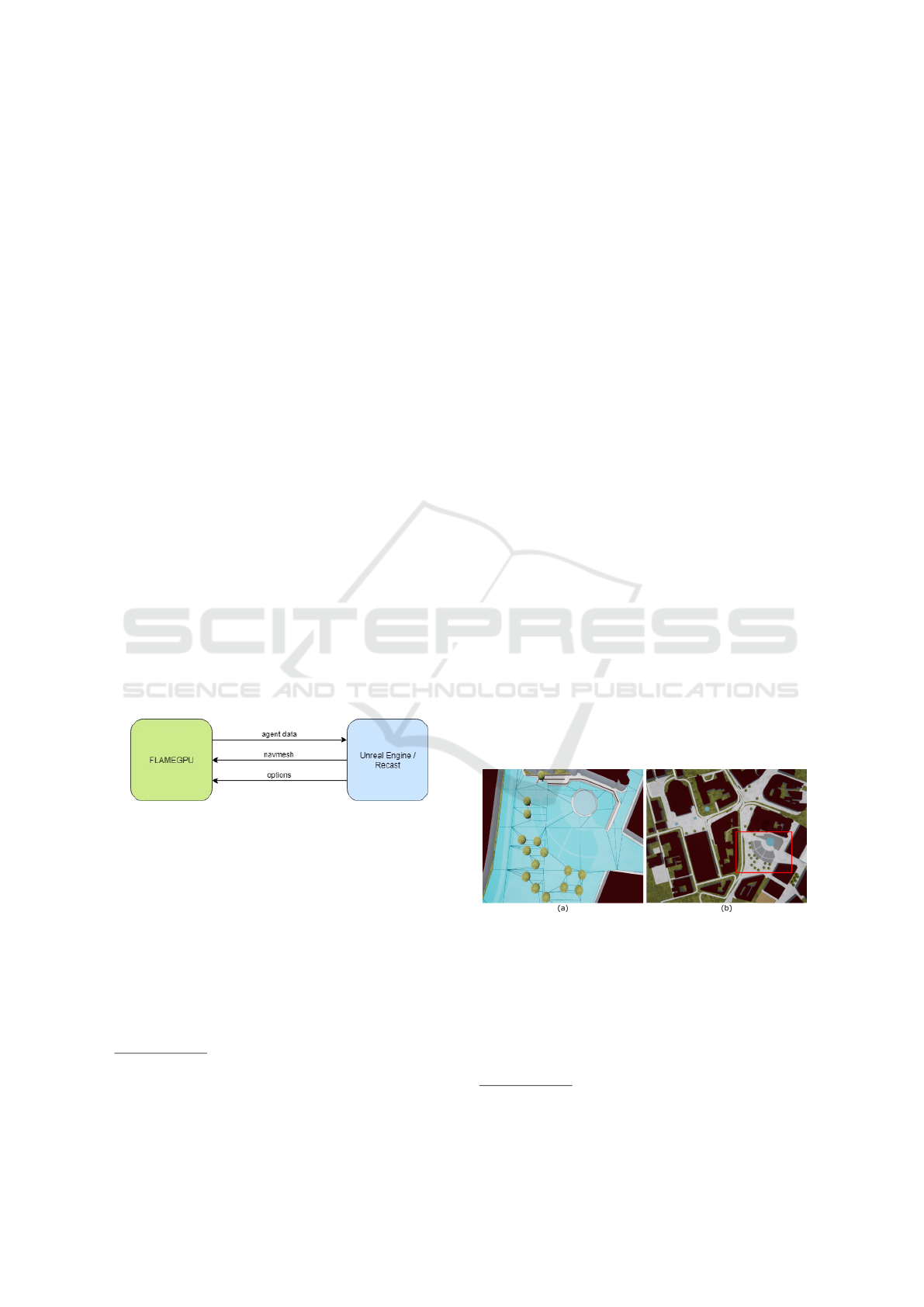
Figure 1 shows an overview of the system and the data
structures that are exchanged. The agent data used in
the FLAMEGPU framework must be available to the
visualisation module running on the CPU, which, in
turn, must send sketched updates to the environment
back to FLAMEGPU to influence the simulation run-
ning on the GPU.
Figure 1: System overview showing the data structures that
are exchanged between GPU (green) and CPU (blue).
3.1 Visualisation
The objective of this module is to provide a visual rep-
resentation of the simulation and to create an interface
where users can use sketching to manipulate the vir-
tual crowd. Additionally, this module is responsible
for the navmesh creation and finding the paths to be
followed by the agents.
The environment is produced using data from
6
https://www.unrealengine.com/en-US/what-is-unreal-
engine-4
7
http://masagroup.github.io/recastdetour/
8
http://www.flamegpu.com
OpenStreetMap
9
. The tool OSM2World
10
is then used
to convert this data into a 3D model before importing
it into the game engine. The selected environment
is an area of a UK city centre (see Figure 2b). Some
modifications were made to the model prior to the im-
port: imperfections on the ground were removed, tree
models were substituted with a new 3D model, and a
few materials were replaced.
3.2 Navmesh
A novel contribution of this paper is the use of a
navmesh to support the sketch-based solution. Pre-
vious work (Gonzalez and Maddock, 2017; Jin et al.,
2008; Patil et al., 2011) used a grid-based approach.
A navmesh approach is a more scalable solution (see
Section 5 for a detailed comparison based on the sce-
narios we use in Section 4).
In our work, the underlying navmesh used to de-
termine the movement of the agents is created with
Recast, which is an open source tool used in games
to automatically create a navmesh from a 3D environ-
ment. Recast allows the creation of tiled navmeshes
which offer the individual update of the tiles rather
than the entire navmesh. At the beginning of the sim-
ulation, the navmesh of all tiles is computed to gener-
ate the polygons (see Figure 2a) – Recast’s mesh gen-
eration process produces some long, thin triangles,
but this does not affect our sketch work. Later up-
dates are only made in affected tiles, which facilitates
real time modification of the mesh. The user has the
option to hide or show the navmesh – in most of the
figures in this paper the navmesh is visible to make it
clear how it is updated based on user inputs.
Figure 2: (a) The tiled navmesh created with Recast and
displayed in Unreal Engine. The underlying square tile pat-
tern is shown, as well as the polygons created to connect dif-
ferent parts of the environment such as buildings and trees.
(b) The environment where the simulation runs. The red
rectangle highlights the area shown in (a).
The Recast software was modified to implement
sketching on top of the navmesh and to update it ac-
cording to user actions (Section 3.4). After every
9
https://www.openstreetmap.org/
10
http://osm2world.org/
GRAPP 2019 - 14th International Conference on Computer Graphics Theory and Applications
44
navmesh change, the shortest path from every poly-
gon to the target is recalculated. This information
is sent to the simulation module through the shared
memory segment.
3.3 Simulation
The agent-based simulation uses the social forces
model (Helbing and Molnar, 1995) to determine the
movement of the agents. Whilst this is a relatively
simple model, it is sufficient to support the combined
sketching work and navmesh use. A more complex
approach could be used if required. The agent mo-
tion is the result of the weighted sum of three forces:
(i) The pedestrian avoidance force for inter-agent col-
lision avoidance. This is computed taking into ac-
count the position and velocity of nearby agents;
(ii) The collision force used to prevent agents collid-
ing with the environment. The polygon edges with-
out neighbours exert a repulsive force on agents de-
pending on the distance; (iii) The goal force to guide
agents to their destination. This is obtained using the
graph (navmesh) sent by the visualisation module.
The graph is formed by nodes (polygons) and the
edges shared by adjacent polygons. Each node con-
tains a list of neighbouring polygons and the connect-
ing edges. This graph is used to calculate the short-
est path from every polygon to all the exits and ar-
eas. The A* algorithm is used to compute the shortest
path – this uses a heuristic value to guide the search
for better performance. A route is computed for each
exit. To create the route, every polygon stores the ad-
jacent polygon leading to the corresponding exit. In
this manner, agent movement can be calculated know-
ing the current polygon and the assigned exit of the
agents. One approach to generate the agent movement
is by following the middle point of the edges connect-
ing the polygons of the shortest route. However, this
would produce unrealistic paths. This problem can
be solved by smoothing the resulting path using The
Simple Stupid Funnel Algorithm (Demyen and Buro,
2006). This technique finds the corners of the path
staying inside the polygons found by the A* route.
3.4 Sketching
The interface, implemented in Unreal, allows the user
to perform a series of actions by sketching or clicking
in the environment. These actions include definition
of agent spawn and goal locations, sketching obsta-
cles to alter the crowd movement, creation of flow
lines to guide the motion of the agents, drawing ar-
eas to create waypoints, and definition of journeys via
storyboards. The entrances and exits are created by
selecting a polygon edge with no neighbours. These
locations define the spawning position of the agents
and also serve as goals.
The first step to update the navmesh is to capture
the user sketch and sample the line into equidistant
points. Each sequence of points can represent an ob-
stacle, a flow line or an area edge. Then, the line is
mapped to the navmesh by marking the area covered
by the sketch. These regions are given an id to dif-
ferentiate among obstacles, flow lines and areas. The
tiles affected by the user sketch are identified and the
navmesh of these tiles is rebuilt with the new infor-
mation.
3.4.1 Barriers
The barrier obstacles are created by marking the af-
fected navmesh area as null. A null area cannot be
crossed and is not used in navigation computation.
The process is made efficient by using the tiles that
the relevant navmesh area overlaps. Each overlapped
tile is divided into an integer grid of voxels, the size of
which can be controlled by a Recast parameter. Ev-
ery voxel in the grid is tested to determine if it lies
within the sketched obstacle region, whereupon it is
marked as empty. Using this information, the con-
tours of the updated walkable areas inside the affected
tiles are calculated and these are used to re-triangulate
this area to obtain the new polygons of the navmesh.
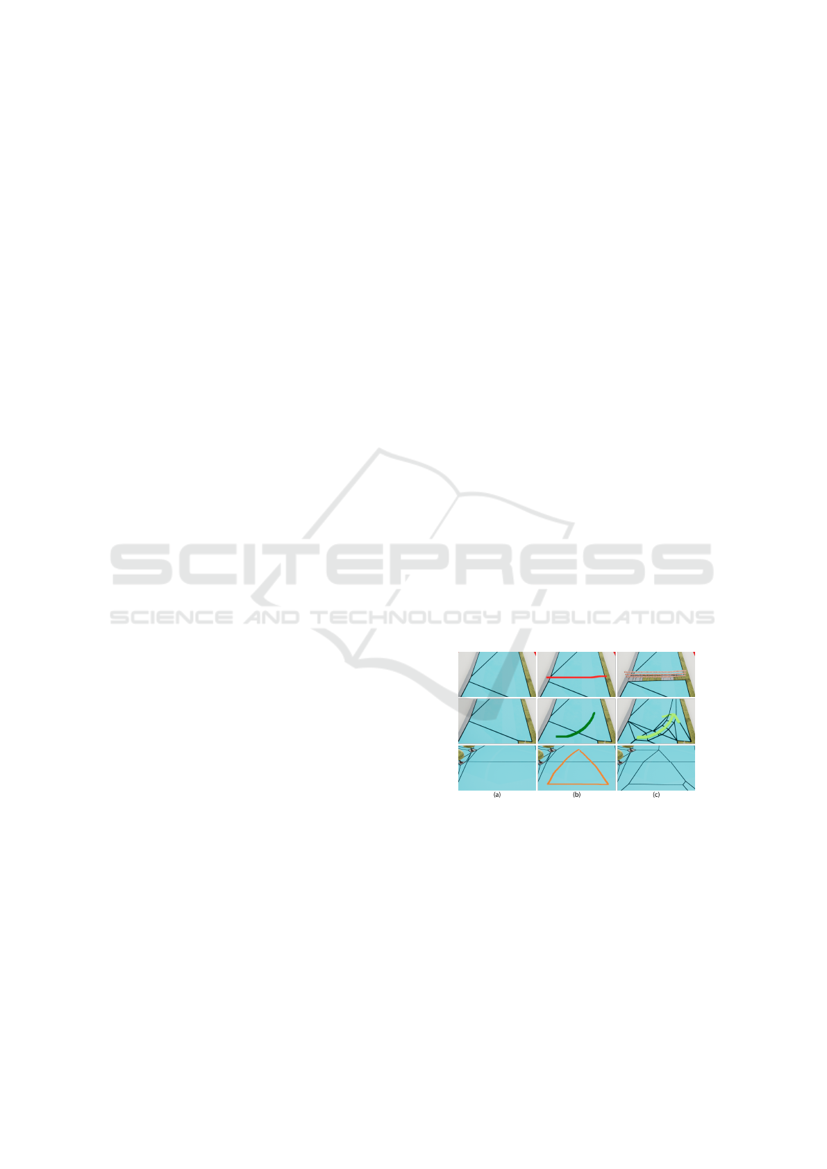
The first row of Figure 3 shows the process of produc-
ing a barrier by sketching a line—navmesh polygons
are generated on both sides of the barrier.
Figure 3: Column (a) original navmesh. Column (b) user-
sketched line. Column (c) Updated navmesh with an obsta-
cle (first row), flow line (second row) and area (third row).
3.4.2 Flow Lines
A sketched flow line is given an id to identify it.
The sketched flow line is divided into a set of poly-
gons which are traversable only in the direction of the
sketch (second row in Figure 3). The cost of travers-
ing a flow line can be changed by the user – a higher
value means that a flow line is more likely to attract
agents from the surrounding area.
A Sketch-based Interface for Real-time Control of Crowd Simulations that Use Navigation Meshes
45
The addition of flow lines converts the navmesh in
the flow line area into a directed graph which means
that adjacent polygons are not necessarily connected
for navigation purposes. Therefore, agents inside flow
lines must follow the complete flow line until the end
of it is reached. The routes to areas and exits are re-
calculated when the cost of traversing the flow lines
is changed.
3.4.3 Areas and Behaviours
The user can create areas in the environment that
serve as waypoints. The shape of the sketched poly-
gon is mapped to the navmesh and the new area is re-
triangulated to eliminate concave polygons, as shown
in the third row of Figure 3. The shortest path from
each navmesh polygon to the area is then computed.
In addition, the interface offers the ability to set the
percentage of agents that will visit each area.
Currently, within an area, a wandering behaviour
is implemented. When an agent reaches an area, it
moves in random directions within the area for a pre-
defined amount of time, before continuing on its jour-
ney. Whilst the idea of areas and behaviours has been
previously suggested (Hughes et al., 2014), the main
difference in our approach is the ability to set the per-
centage of agents visiting and to assign the areas to a
storyboard (Section 3.4.4). In future work other be-
haviours could be assigned to areas.
3.4.4 Storyboards
A storyboard defines the exact journey of agents
throughout the simulation. To create a storyboard, the
user must select an entrance polygon, areas (optional)
and an exit. Once the route is completed, the story-
board is displayed as shown in Figure 4. The selected
polygons and areas are highlighted and the indication
arrows show the order of the storyboard. These ar-
rows are not the actual path followed by the crowd.
Individual pedestrians will calculate their own path
using the navmesh.
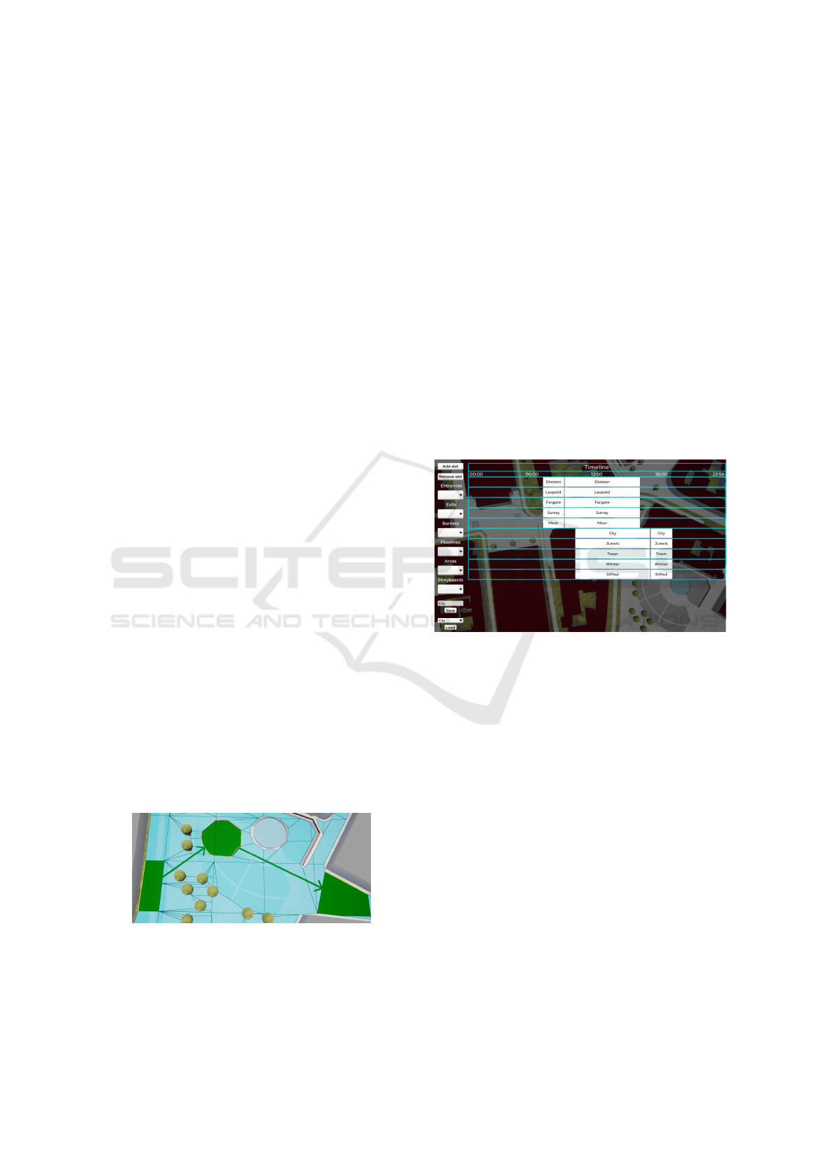
Figure 4: Storyboard created by the user. The selected poly-
gons and areas are highlighted in green. The route begins
at the left entrance, continues to the area in the middle and
ends at the right exit.
Currently, up to ten storyboards can be created per
entrance. The user is able to define the percentage
of pedestrians (spawned at the selected entrance) that
follow the desired storyboard. A menu displays the
existing storyboards and offers editing facilities. If no
storyboard has been created, agents spawn at every
entrance depending on a user-defined emission rate.
Similarly, their exit is selected from all the exits based
on percentages specified by the user. By creating sto-
ryboards, the user defines the exact agent journey.
3.4.5 Timeline
The simulation keeps track of the time allowing the
user to simulate events during a day. Example events
include: open/close entrances and exits; change the
emission rate of an entrance; create barriers, flow
lines, areas and storyboards. In addition, the speed of
the simulation can be increased up to 24x to observe
a day in an hour.
Figure 5: Timeline interface. The elements created by the
user can be selected with the drop-down lists on the left.
These can be dragged into the timeline to determine the time
of the event.
Using the timeline interface, the previously cre-
ated elements can be dragged and dropped into the
timeline to specify their occurrence time. The du-
ration of the events is modified by re-sizing the ele-
ments. The simulation constantly checks for events
and updates the environment accordingly to influence
the pedestrian behaviour. The elements that are not
added to the timeline are considered permanent as
part of the environment. Figure 5 shows the time-
line of the complex environment in Figure 10. In this
example, the emission rate of the named entrances
is changed throughout the day to simulate two peak
travel periods, as people travel to a city centre in the
morning and then leave it in the evening. For exam-
ple, the “Division” entrance has a high flow from 7-
9am, then a low flow until 4pm. These people follow
one of 5 storyboards to different buildings. For the
building ”JLewis”, there is a low leaving flow from
10am-5pm, followed by a high leaving rate from 5-
GRAPP 2019 - 14th International Conference on Computer Graphics Theory and Applications
46
7pm. These people follow storyboards to exit routes
(which are equivalent to the original entrance routes).
4 VALIDATION SCENARIOS
A set of scenarios were simulated to demonstrate the
system’s functionality. A video of the system in ac-
tion is available at https://tinyurl.com/y7waxwfr. The
scenarios were run on an Intel Core i5 6500 with
16GB RAM and an NVIDIA GeForce GTX 1060 SC.
The performance of the system is shown in Table 2.
Table 2: System performance with multiple crowd sizes.
No. Agents fps
1k 118-119
5k 86-87
10k 50-52
20k 24-26
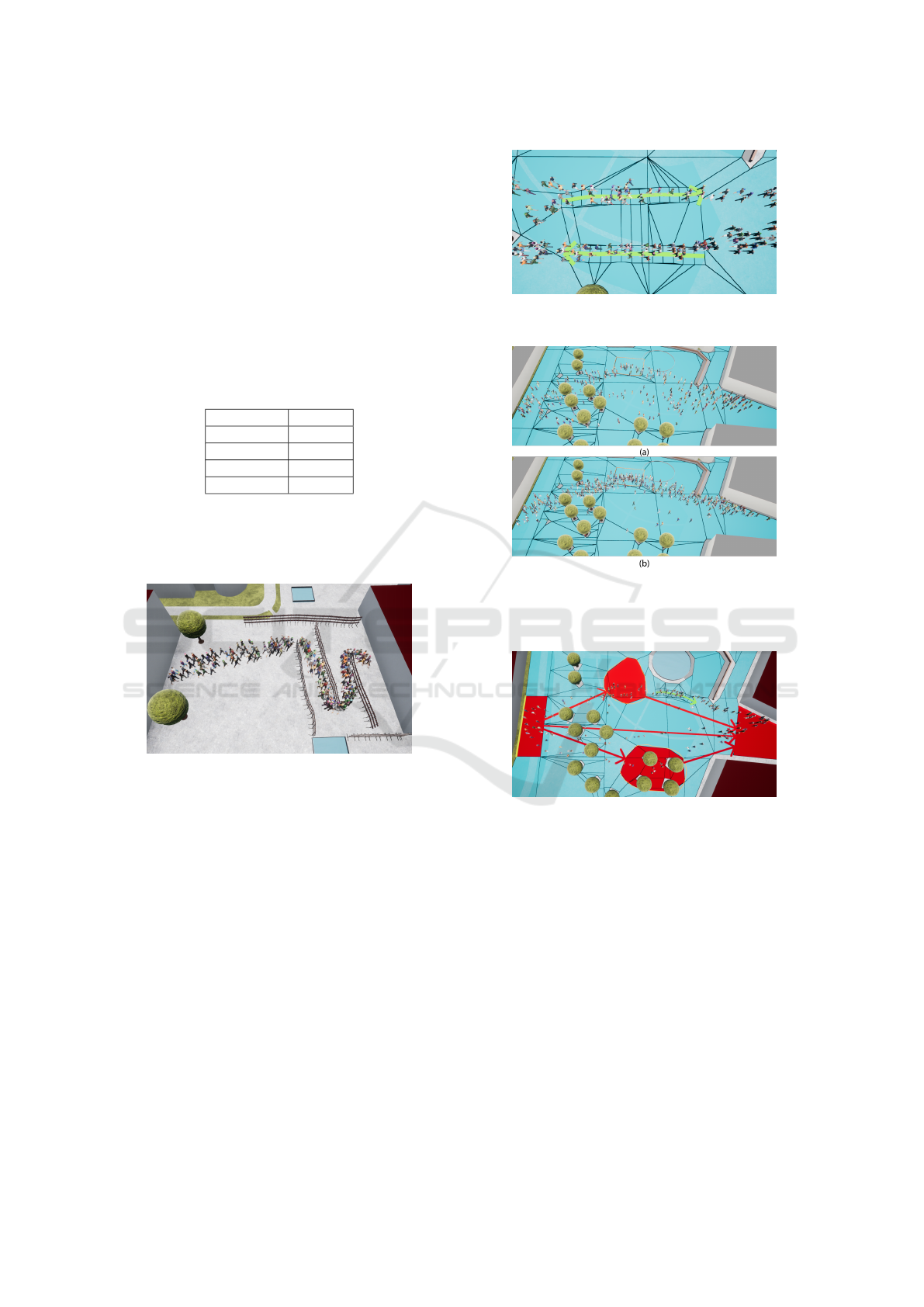
The first scenario is the creation of a queue that
simulates the entrance to a venue. Figure 6 shows a
snake-like corridor created by sketching barriers.
Figure 6: Pedestrians following the path created by the user.
The corridor was built with a set of sketched barriers.
The second scenario shows the use of flow lines
(Figure 7) to control the crowd by forming lanes in
areas such as road crossing points. Lane formation
is a global behaviour that can emerge in agent-based
simulations (Treuille et al., 2006). Our system gives a
user more control over where it occurs. Currently the
user has no control over the width of a flow line. This
could be added but would increase interface complex-
ity. An extension to consider for future work would
be two-way flow lines.
Figure 8 shows the use of areas, which can be used
as waypoints on a journey for a range of scenarios,
e.g. where some pedestrians have to queue at a ticket
machine before continuing in a train station or per-
haps where pedestrians are stopping to watch some
kind of street entertainment before continuing.
Storyboards offer complete control over the paths
to be followed by the crowd. Figure 9 shows three
Figure 7: Pedestrians walking in the direction of the
sketched flow lines.
Figure 8: Pedestrians walking from the right hand side to
the left hand side via the same area (represented by the
orange rectangle) with two different user-controllable area
visit percentages: (a) fifty and (b) ninety.
Figure 9: Pedestrians divided into three equal groups, each
following a different storyboard.
storyboards created by the user – different shades of
the same colour are used for storyboards that belong
to the same entrance, and each entrance is assigned
a different colour for its storyboards. The crowd is
divided into three equal parts, each following a dif-
ferent storyboard. Two storyboards have an interme-
diate area and one directs pedestrians straight from
the entrance to the exit. A flow line is also used near
to the top area. It can be difficult to see the different
shades of colour used for storyboards emanating from
the same entrance because the system allows up to 10
storyboards from one entrance. This is something that
still needs further work.
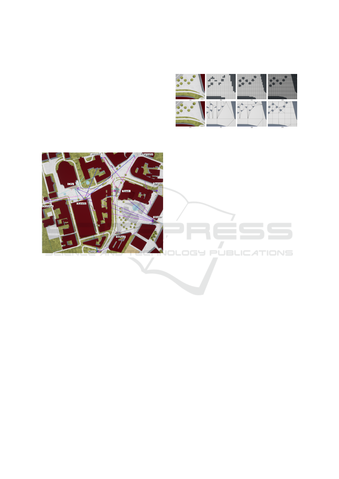
Figure 10 shows a more complex scenario with
10 entrances/exits and 70 storyboards. In this ex-
A Sketch-based Interface for Real-time Control of Crowd Simulations that Use Navigation Meshes
47
ample, a day in a city centre is simulated. Five en-
trances/exits are placed on the outskirts of the city
centre and the other five entrances/exits are located
in buildings. This simulates the flow of people going
to work or visiting the area. The timeline in Figure
5 is used to simulate peak hours. During the morn-
ing the number of agents going to the city centre is
increased, whereas in the early evening, the agents
leave the area. Late evening and night-time are not
modelled. The use of storyboards combined with the
timeline gives non-expert users control over the sim-
ulation to recreate real scenarios. Future work could
look at the use of decision trees in conjunction with
storyboards.
Figure 10: Complex scenario simulating a city centre with
10 entrances/exits and 70 storyboards.
5 GRID VS NAVMESH
This section compares our tiled navmesh approach
with a grid-based approach (Gonzalez and Maddock,
2017) using three criteria: environment representation
and sketch accuracy, memory usage and computation
time.
5.1 Environment Representation and
Sketch Accuracy
The representation accuracy of the grid depends on
its resolution. Low resolution grids use bigger cells
which cover larger areas of the environment, e.g.
walkable surfaces and obstacles. However, a cell can
only be marked as empty or occupied, leading to mis-
representation of the environment. This issue is evi-
dent in objects with circular shapes and when straight
walls are not aligned with the grid, as shown in the
top row of Figure 11, and also when curves and lines
are sketched at angles to the underlying grid.
Figure 11: Grid and navmesh representation of the environ-
ment. Top row shows three grids with different resolutions:
(a) original environment, (b) 128x128, (c) 256x256 and (d)
512x512. Bottom row shows three navmeshes with differ-
ent voxel size: (e) original environment, (f) 0.5, (g) 0.25 and
(h) 0.1.
The navmesh provides a more accurate represen-
tation of the environment since it is based on the ge-
ometry of the model. Reducing the voxel size re-
sults in a better representation but also increases the
number of tiles and polygons. An advantage of the
navmesh over the grid is that polygons cover larger ar-
eas compared to the cells of the grid, therefore fewer
polygons are required to cover the entire walkable
surface. The bottom row of Figure 11 shows the
same zoomed area of the environment represented by
navmeshes with different voxel size. As the voxel size
is reduced, the number of polygons increases and the
accuracy of the representation improves. Sketch pre-
cision is also better for the navmesh approach, since
the navmesh does not require a small voxel size to
represent a line in a reasonably accurate way, whereas
the grid approach must increase its resolution.
In both the grid-based approach and the navmesh-
based approach, increasing the accuracy of the rep-
resentation impacts on the the memory used and the
computation efficiency. Bigger environments require
more data to be accurately represented, therefore a
trade-off has to be made between environment rep-
resentation, memory usage and computation time.
5.2 Memory Usage
A grid is represented by a two-dimensional array with
each element set to empty or occupied. However, an-
other structure is required to store the shortest paths
to the goals. Gonzalez and Maddock (2017) used a
flowmap per exit (as in (Karmakharm et al., 2010))
to store these paths. The maps are grids where ev-
ery cell stores a force directing agents to their target.
Table 3 shows the memory used by grids of differ-
ent sizes with multiple exits. Figure 12 illustrates that
the memory used is directly proportional to the grid
GRAPP 2019 - 14th International Conference on Computer Graphics Theory and Applications
48
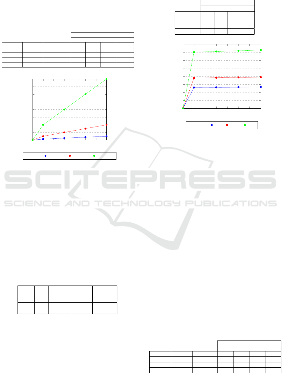
resolution and the number of exits. When the num-
ber of cells is quadrupled, the memory usage is also
increased fourfold. The grid approach has poor scala-
bility.
Table 3: Memory used by the grid approach with three dif-
ferent sizes.
Structure memory (kB)
No. exits
Grid size No. cells
Grid
memory (kB)
1 3 5 7
128x128 16,384 128 256 512 768 1,024
256x256 65,536 256 1,024 2,048 3,072 4,096
512x512 262,144 512 4,096 8,192 12,288 16,384
0 1 2 3 4
5 6
7
0
2
4
6
8
10
12
14
16
No. exits
Memory (MB)
Grid size 128x128 256x256 512x512
Figure 12: Memory used by three grids with multiple exits.
The navmesh is represented by a structure that
stores tiles, polygons, vertices and polygon adjacency,
as well as other information required to find paths be-
tween polygons. In addition, an extra structure is de-
fined to store the shortest routes, entrances, exits, ar-
eas, storyboards and a search grid used to accelerate
the polygon search to determine the position of each
agent. An advantage of the grid-based approach is
that the location of the agent can be directly mapped
to a grid cell when determining the next movement.
Table 4 shows the number of tiles, polygons and ver-
tices generated for three voxel sizes and also the mem-
ory used by the navmesh structure.
Table 4: Number of elements generated by the navmesh
with different voxel size, and memory used.
Voxel
size
No.
tiles
No.
polygons
No.
vertices
Memory
used (kB)
0.5 44 516 1,363 80.2
0.25 168 911 2,643 163
0.1 921 2,213 7,310 499
Table 5 shows the memory used by the additional
structure with different voxel sizes and multiple exits.
Similar to the grid, memory usage also increases with
the number of tiles, polygons and exits, however, the
growth ratio is lower, as shown in Figure 13. Since
the navmesh approach scales better with the size of
the environment, it is a more suitable option for large
environments in terms of memory usage.
Table 5: Memory used by the structure storing the shortest
paths with multiple exits.
Structure memory (kB)
No. exits
Voxel size 1 3 5 7
0.5 260 263 265 267
0.25 379 387 386 390
0.1 701 710 719 728
0 1 2 3 4
5 6
7
0
100
200
300
400
500
600
700
800
No. exits
Memory (kB)
Voxel size 0.5 0.25 0.1
Figure 13: Memory used by three navmeshes with multiple
exits.
5.3 Computation Time
To compare the performance of both approaches the
time taken by three functions was measured: con-
struction, update and pathfinding. A grid is built by
using vertical raycasting to segment the world into
cells. The update time is the amount of time taken to
change the values of the grid when the environment
is dynamically updated. Pathfinding uses a wavefront
propagation algorithm to calculate the distance from
each grid cell to the corresponding goal and the re-
sult is smoothed to create more realistic paths. Table
6 shows the time taken by these functions for three
grids with multiple exits. The update times are simi-
lar since only the affected cells are updated. However,
the paths must be recalculated, which requires more
time as the grid resolution increases.
The process of building and updating a navmesh
is described in Section 3. Table 7 shows the times for
these processes and the pathfinding algorithm. The
construction time is an issue for the navmesh ap-
proach. For a static environment, the navmesh can
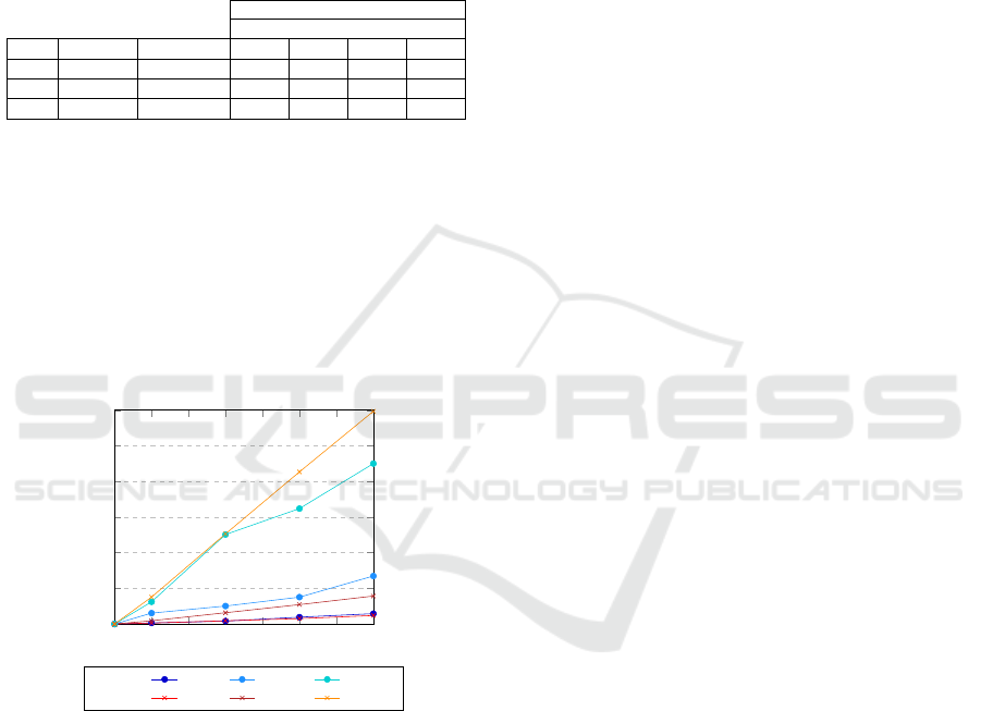
Table 6: Time taken to create and update three grids of dif-
ferent sizes and to find the shortest paths for several goals.
Pathfinding (s)
No. exits
Size Build (s) Update (s) 1 3 5 7
128x128 0.071 0.00003 0.003 0.008 0.019 0.029
256x256 0.279 0.0001 0.031 0.050 0.075 0.135
512x512 0.944 0.0005 0.062 0.251 0.324 0.45
A Sketch-based Interface for Real-time Control of Crowd Simulations that Use Navigation Meshes
49
be created just once in an offline stage. For a dy-
namic environment, such as a sketching environment,
the navmesh must be recalculated when the environ-
ment changes. However, using the tiled approach of
Recast, where the mesh is updated locally, amelio-
rates the cost. The update time is similar for each
case since the number of voxels per tile is the same.
Table 7: Time taken to create and update three navmeshes
with different voxel sizes and to find the shortest paths for
several goals.
Pathfinding (s)
No. exits
Size Build (s) Update (s) 1 3 5 7
0.5 0.134 0.003 0.003 0.009 0.015 0.024
0.25 0.492 0.002 0.009 0.031 0.054 0.078
0.1 3.433 0.004 0.076 0.253 0.427 0.597
Figure 14 plots the time taken by the pathfinding
algorithm for different size grids and navmeshes. For
the navmesh, the major issue is that this time increases
as the number of polygons grows. Sketching barri-
ers, flowlines and areas creates more polygons, thus
exacerbating the problem. Higher computation times
could compromise the real time interaction with the
simulation. This may be an issue in complex environ-
ments or with a large number of destinations.
0 1 2 3 4
5 6
7
0
0.1
0.2
0.3
0.4
0.5
0.6
No. exits
seconds
Grid 128x28 256x256 512x512
Navmesh 0.5 0.25 0.1
Figure 14: Time taken in seconds to calculate the shortest
paths in grids and navmeshes with different sizes.
6 CONCLUSIONS
This paper has presented a solution for real-time con-
trol of virtual crowds without the need for technical
knowledge and complex parameter tuning. Users can
guide the pedestrian flow by sketching directly in the
environment while the simulation is running. Multi-
ple elements can be defined by sketching or clicking:
entrances/exits, obstacles to block paths, flow lines
to guide agents, waypoint areas, and storyboards to
specify the journeys of the pedestrians. A timeline
interface administers the simulation of events through
the day. The underlying navigation approach used is a
navmesh created with a modified version of the open
source tool Recast. The navmesh is a better alter-
native for navigation, since it represents the environ-
ment more accurately and requires less memory than
the grid-based approach, although computation time
is similar for both approaches. However, the navmesh
approach has some limitations. The initial construc-
tion time (which can be done in an offline step) and
the addition of new elements increases the number of
polygons and consequently the path-finding computa-
tion time. Future work will look at ways to mitigate
this problem. We also intend to run a user study look-
ing at the ease of use of the interface as environment
complexity increases.
REFERENCES
Akaydın, A. and G
¨
ud
¨
ukbay, U. (2013). Adaptive grids: an
image-based approach to generate navigation meshes.
Optical Engineering, 52(2):027002–027002.
Allen, T., Parvanov, A., Knight, S., and Maddock, S. (2015).
Using Sketching to Control Heterogeneous Groups. In
Proc. CGVC 2015.
Berseth, G., Kapadia, M., and Faloutsos, P. (2016).
ACCLMesh: curvature-based navigation mesh gen-
eration: Curvature-based navigation mesh genera-
tion. Computer Animation and Virtual Worlds, 27(3-
4):195–204.
Chenney, S. (2004). Flow Tiles. In Proc SCA 2004, pages
233–242.
Demyen, D. and Buro, M. (2006). Efficient triangulation-
based pathfinding. In Proc. AAAI’06, pages 942–947.
Gonzalez, L. R. M. and Maddock, S. (2017). Sketching
for Real-time Control of Crowd Simulations. In Proc.
CGVC 2017.
Gu, Q. and Deng, Z. (2011). Formation sketching: An ap-
proach to stylize groups in crowd simulation. In Proc.
GI 2011, pages 1–8.
Gu, Q. and Deng, Z. (2013). Generating freestyle group
formations in agent-based crowd simulations. IEEE
Computer Graphics and Applications, 33(1):20–31.
Hale, D. H. and Youngblood, G. M. (2009). Full 3d spa-
tial decomposition for the generation of navigation
meshes. In AIIDE 2009, pages 142–147.
Hale, D. H., Youngblood, G. M., and Dixit, P. N. (2008).
Automatically-generated Convex Region Decomposi-
tion for Real-time Spatial Agent Navigation in Virtual
Worlds. AIIDE, 8:173–8.
Hauri, S., Alonso-Mora, J., Breitenmoser, A., Siegwart, R.,
and Beardsley, P. (2014). Multi-robot formation con-
trol via a real-time drawing interface. In Field and
Service Robotics, pages 175–189. Springer.
Helbing, D. (1991). A mathematical model for the behavior
of pedestrians. Behavioral Science, 36(4):298–310.
GRAPP 2019 - 14th International Conference on Computer Graphics Theory and Applications
50

Helbing, D. and Molnar, P. (1995). Social force model for
pedestrian dynamics. Physical review E, 51(5):4282.
Henry, J., Shum, H. P. H., and Komura, T. (2012).
Environment-aware Real-time Crowd Control. In
Proc. EUROSCA’12, pages 193–200.
Hughes, R., Ond
˘
rej, J., and Chaurasia, G. (2014). Sketch-
Based Annotation and Authoring of Geometrically
Sparse 3d Environments. Technical report, TCD-CS-
2014-01, School of Computer Science and Statistics,
Trinity College Dublin.
Jin, X., Xu, J., Wang, C. C., Huang, S., and Zhang,
J. (2008). Interactive Control of Large-Crowd
Navigation in Virtual Environments Using Vector
Fields. IEEE Computer Graphics and Applications,
28(6):37–46.
Jordao, K., Charalambous, P., Christie, M., Pettr
´
e, J., and
Cani, M.-P. (2015). Crowd art: Density and flow
based crowd motion design. In Proc. MIG ’15, pages
167–176.
Jordao, K., Pettr
´
e, J., Christie, M., and Cani, M.-P. (2014).
Crowd sculpting: A space-time sculpting method for
populating virtual environments. Comput. Graph. Fo-
rum, 33(2):351–360.
Kallmann, M. (2005). Path planning in triangulations. In
Proceedings of the IJCAI workshop on reasoning, rep-
resentation, and learning in computer games, pages
49–54.
Kallmann, M., Bieri, H., and Thalmann, D. (2003).
Fully Dynamic Constrained Delaunay Triangulations.
In Geometric Modelling for Scientific Visualization,
Springer-Verlag, 2003.
Karmakharm, T., Richmond, P., and Romano, D. M. (2010).
Agent-based Large Scale Simulation of Pedestrians
With Adaptive Realistic Navigation Vector Fields.
TPCG, 10:67–74.
Kim, J., Seol, Y., Kwon, T., and Lee, J. (2014). Interactive
Manipulation of Large-scale Crowd Animation. ACM
Trans. Graph., 33(4):83:1–83:10.
Kim, M., Hwang, Y., Hyun, K., and Lee, J. (2012). Tiling
motion patches. In Proc. SCA ’12, pages 117–126.
Kim, M., Hyun, K., Kim, J., and Lee, J. (2009). Synchro-
nized multi-character motion editing. ACM Trans.
Graph., 28(3):79:1–79:9.
Kwon, T., Lee, K. H., Lee, J., and Takahashi, S. (2008).
Group Motion Editing. In Proc. SIGGRAPH 2008,
pages 80:1–80:8.
Lee, K. H., Choi, M. G., and Lee, J. (2006). Motion patches:
Building blocks for virtual environments annotated
with motion data. ACM Trans. Graph., 25(3):898–
906.
McIlveen, J., Maddock, S., Heywood, P., and Richmond, P.
(2016). PED: Pedestrian Environment Designer. In
Proc. CGVC 2016.
Millan, E. and Rudomin, I. (2005). Agent paint: Intuitive
specification and control of multiagent animations. In
Proc. CASA.
Musse, S. R. and Thalmann, D. (1997). A model of human
crowd behavior: Group inter-relationship and colli-
sion detection analysis. In Computer Animation and
Simulation’97, pages 39–51.
Oliva, R. and Pelechano, N. (2011). Automatic genera-
tion of suboptimal navmeshes. In Proc MIG’11, pages
328–339, Berlin, Heidelberg.
Oliva, R. and Pelechano, N. (2013). NEOGEN: Near op-
timal generator of navigation meshes for 3d multi-
layered environments. Computers & Graphics,
37(5):403–412.
Oshita, M. and Ogiwara, Y. (2009). Sketch-based interface
for crowd animation. In International Symposium on
Smart Graphics, pages 253–262. Springer.
Owen, M., Galea, E., and Lawrence, P. (1996). The exodus
evacuation model. Fire Engineers Journal, 56:26–30.
Pan, X., Han, C. S., Dauber, K., and Law, K. H. (2007).
A multi-agent based framework for the simulation of
human and social behaviors during emergency evacu-
ations. AI & SOCIETY, 22(2):113–132.
Patil, S., Van Den Berg, J., Curtis, S., Lin, M. C., and
Manocha, D. (2011). Directing crowd simulations us-
ing navigation fields. IEEE Transactions on Visual-
ization and Computer Graphics, 17(2):244–254.
Pelechano, N., Allbeck, J. M., and Badler, N. I. (2007).
Controlling Individual Agents in High-density Crowd
Simulation. In Proc. SCA ’07, pages 99–108.
Pelechano, N., O’Brien, K., Silverman, B., and Badler, N.
(2005). Crowd simulation incorporating agent psy-
chological models, roles and communication. Techni-
cal report, Center for human modeling and simulation,
Pennsylvania University, USA.
Rao, Y., Chen, L., Liu, Q., Lin, W., Li, Y., and Zhou, J.
(2011). Real-time control of individual agents for
crowd simulation. Multimedia Tools and Applications,
54(2):397–414.
Reynolds, C. W. (1987). Flocks, herds and schools: A
distributed behavioral model. ACM SIGGRAPH com-
puter graphics, 21(4):25–34.
Reynolds, C. W. (1999). Steering behaviors for autonomous
characters. In Game developers conference, volume
1999, pages 763–782.
Reynolds, C. W. (2000). Interaction with groups of au-
tonomous characters. In Game developers conference,
volume 2000, page 83.
Richmond, P. and Romano, D. M. (2008). A high perfor-
mance framework for agent based pedestrian dynam-
ics on gpu hardware. Proc. EUROSIS ESM, 20:27–29.
Shen, Y., Henry, J., Wang, H., Ho, E. S., Komura, T., and
Shum, H. P. (2018). Data-Driven Crowd Motion Con-
trol with Multi-touch Gestures. Computer Graphics
Forum, 37(6):382–394.
Snook, G. (2000). Simplified 3d movement and pathfinding
using navigation meshes. Game Programming Gems,
1(1):288–304.
Sung, M., Gleicher, M., and Chenney, S. (2004). Scalable
behaviors for crowd simulation. In Computer Graph-
ics Forum, volume 23, pages 519–528.
Takahashi, S., Yoshida, K., Kwon, T., Lee, K. H., Lee, J.,
and Shin, S. Y. (2009). Spectral-Based Group Forma-
tion Control. Computer Graphics Forum.
Treuille, A., Cooper, S., and Popovi
´
c, Z. (2006). Contin-
uum Crowds. In Proc. SIGGRAPH 2006, pages 1160–
1168.
A Sketch-based Interface for Real-time Control of Crowd Simulations that Use Navigation Meshes
51

Ulicny, B., Ciechomski, P. d. H., and Thalmann, D.
(2004). Crowdbrush: Interactive Authoring of Real-
time Crowd Scenes. In Proc. SCA’04.
Ulicny, B. and Thalmann, D. (2001). Crowd simulation for
interactive virtual environments and vr training sys-
tems. In Computer Animation and Simulation 2001,
pages 163–170.
Ulicny, B. and Thalmann, D. (2002). Towards Interactive
Real-Time Crowd Behavior Simulation. Computer
Graphics Forum, 21(4):767–775.
Van Toll, W., Cook, A. F., and Geraerts, R. (2011). Naviga-
tion meshes for realistic multi-layered environments.
In 2011 IEEE/RSJ International Conference on Intel-
ligent Robots and Systems, pages 3526–3532.
van Toll, W. G., Cook, A. F., and Geraerts, R. (2012). A
navigation mesh for dynamic environments: A nav-
igation mesh for dynamic environments. Computer
Animation and Virtual Worlds, 23(6):535–546.
Xu, J., Jin, X., Yu, Y., Shen, T., and Zhou, M. (2008).
Shape-constrained flock animation. Computer Anima-
tion and Virtual Worlds, 19(3-4):319–330.
Xu, M., Wu, Y., and Ye, Y. (2012). Smooth and efficient
crowd transformation. In Proceedings of the 20th
ACM international conference on Multimedia, pages
1189–1192. ACM.
Xu, M., Wu, Y., Ye, Y., Farkas, I., Jiang, H., and Deng, Z.
(2015). Collective Crowd Formation Transform with
Mutual Information-Based Runtime Feedback. Com-
puter Graphics Forum, 34(1):60–73.
Yeh, H., Curtis, S., Patil, S., van den Berg, J., Manocha,
D., and Lin, M. (2008). Composite agents. In Proc.
SCA’08, pages 39–47.
Yersin, B., Ma
¨
ım, J., Ciechomski, P., Schertenleib, S., and
Thalmann, D. (2005). Steering a virtual crowd based
on a semantically augmented navigation graph. In
Proc. V-CROWDS’05, pages 169–178.
Yersin, B., Ma
¨
ım, J., Pettr
´
e, J., and Thalmann, D. (2009).
Crowd patches: Populating large-scale virtual envi-
ronments for real-time applications. In Proc. I3D’09,
pages 207–214.
Yu, Q. and Terzopoulos, D. (2007). A decision network
framework for the behavioral animation of virtual hu-
mans. In Proc. SCA’07, pages 119–128.
Zhang, P., Liu, H., and Ding, Y.-h. (2015). Crowd simula-
tion based on constrained and controlled group forma-
tion. The Visual Computer, 31(1):5–18.
Zheng, L., Zhao, J., Cheng, Y., Chen, H., Liu, X., and
Wang, W. (2014). Geometry-constrained crowd for-
mation animation. Computers & Graphics, 38:268–
276.
GRAPP 2019 - 14th International Conference on Computer Graphics Theory and Applications
52
