
Unifying Modeling and Programming with Valkyrie
Johannes Schr
¨
opfer and Thomas Buchmann
Chair of Applied Computer Science I, University of Bayreuth, Universit
¨
atsstrasse 30, 95440 Bayreuth, Germany
Keywords:
Model-driven Development, UML, ALF, Code Generation, Agile Development, Model Transformations,
Behavioral Models.
Abstract:
Raising the level of abstraction when developing a software system is the driving force behind Model-driven
software development (MDSD) – a software engineering paradigm which gained more and more attention
during the last decade. The current state of the art in MDSD allows software engineers to capture the static
structure in a model, e.g., by using class diagrams provided by the Unified Modeling Language (UML), and
to generate source code from it. Furthermore, when it comes to expressing the behavior, i.e., method bodies,
the UML offers a set of diagrams which may be used for this purpose. Unfortunately, not all UML diagrams
come with a precisely defined execution semantics and thus, code generation is hindered. Recently, the OMG
issued the standard for an Action Language for Foundational UML (ALF) which allows for textual modeling
of software system and which provides a precise execution semantics. In this paper, a tight integration between
our UML-based CASE tool and our ALF tool is presented. The resulting tool chain allows to express structure
and behavior of a software system on the model level and to generate fully executable Java source code.
1 INTRODUCTION
The motivation behind Model-driven software de-
velopment (MDSD) (V
¨
olter et al., 2006) is to re-
place low-level programming with the development
of high-level models. Starting from an initial model
capturing the requirements, a set of models over mul-
tiple levels of abstraction is derived until finally code
is generated. Modeling languages are usually defined
with the help of metamodels in the context of object-
oriented modeling.
Model-driven Architecture (MDA) (Mellor et al.,
2004) is the standard process for model-driven soft-
ware engineering. In the MDA context, model trans-
formations are typically chained. A platform inde-
pendent model (PIM) is refined to a platform spe-
cific model (PSM) using a series of subsequent model
transformations.
MDSD puts strong emphasis on the development
of high-level models rather than on the source code.
While in model-based development, models are con-
sidered as documentation or as informal guidelines on
how to program the actual system, models used for
MDSD have a well-defined syntax and semantics.
Over the years, the Unified Modeling Language
(UML) (OMG, 2015b) has been established as the
standard modeling language for model-driven devel-
opment and in particular for MDA. UML provides a
wide range of diagrams classified into structural and
behavioral ones. When model-driven development
needs to be supported in a full-fledged way, having
executable models from which code may be generated
is crucial. However, generating executable code re-
quires a precise and well-defined execution semantics
from behavioral models. Unfortunately, not all behav-
ioral diagrams provided by the UML are quipped with
such a well-defined semantics. As a consequence,
software engineers nowadays need to supply method
bodies in the generated code using traditional pro-
gramming techniques.
This circumstance is called “code generation
dilemma” (Buchmann and Schw
¨
agerl, 2015) and
refers to the fact that automatically generated code
which is obtained from higher-level models needs to
be extended with hand-written code. Typically, these
different fragments of the software system evolve sep-
arately which may lead to inconsistencies. Round-trip
engineering (Buchmann and Westfechtel, 2016) may
help to keep the structural parts consistent. However,
there’s still no adequate representation of the manu-
ally supplied behavioral fragments.
Recently, the Object Management Group (OMG)
issued the standard for the Action Language for Foun-
dational UML (ALF) (OMG, 2013a) which provides
a textual surface notation for a foundational subset of
UML models (fUML) (OMG, 2013b). The fUML
Schröpfer, J. and Buchmann, T.
Unifying Modeling and Programming with Valkyrie.
DOI: 10.5220/0007259600250036
In Proceedings of the 7th International Conference on Model-Driven Engineering and Software Development (MODELSWARD 2019), pages 25-36
ISBN: 978-989-758-358-2
Copyright
c
2019 by SCITEPRESS – Science and Technology Publications, Lda. All rights reserved
25

standard provides a precise execution semantics for
the UML subset which allows for the generation of
executable code. The ALF standard includes a sub-
set of UML class diagrams which are used to model
the static structure of the software system. Behavior
is modeled using activities and statements to further
refine them. The textual concrete syntax allows for a
Java-like specification of method bodies.
In the academic world, the de-facto standard for
research dedicated to model-driven engineering is the
Eclipse Modeling Framework (EMF) (Steinberg et al.,
2009). It strictly focuses on principles from object-
oriented modeling and only provides core concepts
for defining classes, attributes and relationships be-
tween classes. EMF is based on its metamodel Ecore
which basically resembles Essential MOF (EMOF),
a subset of MOF (OMG, 2015a). EMF and its sur-
rounding technologies are the basis for the work pre-
sented in this paper.
This paper extends previous work (Buchmann,
2017) to achieve a tight integration of our ALF edi-
tor (Buchmann and Rimer, 2016) and our UML-based
CASE tool (Buchmann, 2012). In the current paper
we present a much tighter integration of UML and
ALF editing tools which result in an integrated tool
chain that allows for graphical structural modeling
and textual behavioral modeling of a software system
for which fully executable Java code may be gener-
ated.
The paper is structured as follows: Related work is
discussed in Section 2. In Section 3, a brief overview
of the used frameworks and tools is given. Our solu-
tion is explained in Section 4. Furthermore, an exam-
ple demonstrating the use of our integrated tool chain
in a typical model-driven development process is pre-
sented in Section 5. A discussion is given in Section
6, while Section 7 concludes the paper.
2 RELATED WORK
Many different tools and approaches have been pub-
lished in the last few years, which address model-
driven development and especially modeling behav-
ior. The resulting tools rely on textual or graphical
syntaxes, or a combination thereof. While some tools
come with code generation capabilities, others only
allow to create models and thus only serve as a visu-
alization tool.
Xcore
1
recently gained more and more attention
in the modeling community. It provides a textual con-
crete syntax for Ecore models allowing to express the
1
http://wiki.eclipse.org/Xcore
structure as well as the behavior of the system. In
contrast to ALF, the textual concrete syntax is not
based on an official standard. Xcore relies on Xbase
– a statically typed expression language built on Java
– to model behavior. Executable Java code may be
generated from Xcore models. Just like the realiza-
tion of ALF presented in this paper, Xcore blurs the
gap between Ecore modeling and Java programming.
In contrast to ALF, the behavioral modeling part of
Xcore has a strongly procedural character. As a con-
sequence an object-oriented way of modeling is only
possible to a limited extent. E.g. there is no way to
define object constructors to describe the instantiation
of objects of a class. Since Xcore reuses the EMF
code generation mechanism (Steinberg et al., 2009),
the factory pattern is used for object creation. Further-
more, ALF provides more expressive power since it is
based on fUML, while Xcore only addresses Ecore.
Another textual modeling language, designed for
model-oriented programming is provided by Umple
2
.
The language has been developed independently from
the EMF context and may be used as an Eclipse plu-
gin or via an online service. In its current state, Umple
allows for structural modeling with UML class dia-
grams and describing behavior using state machines.
A code generation engine allows to translate Umple
specifications into Java, Ruby or PHP code. Umple
scripts may also be visualized using a graphical no-
tation. Unfortunately, the Eclipse based editor only
offers basic functions like syntax highlighting and a
simple validation of the parsed Umple model. Umple
offers an interesting approach which aims at assisting
developers in rasing the level of abstraction (“umpli-
fication”) in their programs (Lethbridge et al., 2010).
Using this approach, a Java program may be stepwise
translated into an Umple script. The level of abstrac-
tion is raised by using Umple syntax for associations.
Fujaba (The Fujaba Developer Teams from
Paderborn, Kassel, Darmstadt, Siegen and Bayreuth,
2005) is a graphical modeling language based on
graph transformations which allows to express both
the structural and the behavioral part of a software
system on the modeling level. Furthermore, Fujaba
provides a code generation engine that is able to trans-
form the Fujaba specifications into executable Java
code. Behavior is specified using story diagrams.
A story diagram resembles UML activity diagrams,
where the activities are described using story patterns.
A story pattern specifies a graph transformation rule
where both the left hand side and the right hand side
of the rule are displayed in a single graphical nota-
tion. While story patterns provide a declarative way
to describe manipulations of the runtime object graph
2
http://cruise.site.uottawa.ca/umple
MODELSWARD 2019 - 7th International Conference on Model-Driven Engineering and Software Development
26
on a high level of abstraction, the control flow of a
method is on a rather basic level as the control flow in
activity diagrams is on the same level as control flow
diagrams. As a case study (Buchmann et al., 2011)
revealed, software systems only contain a low num-
ber of problems which require complex story patterns.
The resulting story diagrams nevertheless are big and
look complex because of the limited capabilities to
express the control flow.
The graphical UML modeling tool Papyrus
(Guermazi et al., 2015) allows to create UML, SysML
and MARTE models using various diagram editors.
Additionally, Papyrus offers dedicated support for
UML profiles which includes customizing the Pa-
pyrus UI to get a DSL-like look and feel. Papyrus
is equipped with a code generation engine allowing
for producing source code from class diagrams (cur-
rently Java and C++ is supported). Future versions
of Papyrus will also come with an ALF editor. A pre-
liminary version of the editor is available and allows a
glimpse on its provided features. The textual ALF ed-
itor is integrated as a property view and may be used
to textually describe elements of package or class dia-
grams. Furthermore, it allows to describe the behavior
of activities. The primary goal of the Papyrus ALF in-
tegration is using graphical and textual syntax as alter-
native representations of the same view on the model
and not executing behavioral specifications by gener-
ating source code. While Papyrus strictly focuses on a
forward engineering process (from UML to ALF), the
approach presented in this paper explicitly addresses
round-trip engineering.
Compared with our own solution presented in
(Buchmann, 2017), the approach discussed in this pa-
per provides a much tighter integration of UML and
ALF modeling in one single tool. The motivation be-
hind our approach presented in this paper is the com-
bination of graphical and textual modeling in an in-
tegrated tool in a way such that the most appropriate
formalism is used depending on the considered model
elements; while structure is represented pretty intu-
itively using graphical elements, behavioral model el-
ements can be expressed very precisely by a textual
language. For this purpose, only ALF operations are
persisted, presented and edited textually, i.e., all other
aspects of the ALF model are hidden. The modeler
may focus on the current task which results in a lower
cognitive complexity exposed to the user. Further-
more, instead of providing two different editors which
are not connected to each other, the ALF editor is now
integrated visually in the graphical editing process.
When the user clicks an operation within the UML
model, a specific view shows the corresponding ALF
operation containing the method body; UML model
and ALF text are displayed at the same time. Addi-
tionally, some actions of the tool chain are bundled
such that the user does not have to take care about the
technical details running in the background.
3 BACKGROUND
In this section we give a brief background on the
frameworks and tools that are used for the integrated
modeling environment described in this paper.
3.1 Valkyrie
In this subsection, a conceptual overview about UML
modeling tool Valkyrie (Buchmann, 2012) is given.
Requirements
Elicitation
Analysis & Design
Source Code
Use Case
Diagrams
Activity Diagrams
Package Diagram
Class Diagrams
Activity
Diagrams
State
Charts
Application CodeTest Cases
Refinement
Update
Code Generation
already supported
planned
Reverse Engineering
Refactoring
Object
Diagrams
Figure 1: Valkyrie’s diagrams and relations.
Figure 1 shows an overview about the diagrams
currently supported by Valkyrie and their usage in the
different phases of the software engineering process.
Use case diagrams and activity diagrams are used dur-
ing requirements engineering. In that case, activity
diagrams serve as a formalism to further detail single
use cases. Analysis and design is supported through
package diagrams, class diagrams, object diagrams,
activity diagrams and state charts respectively. Fur-
thermore, classes may be refined by state charts defin-
ing a protocol state machine. In that case, the state
chart defines valid states of a class. The transitions
defined in the state chart can be called from operation
implementations.
Valkyrie itself has been developed in a highly
model-driven way. Using the Eclipse UML2 meta
model
3
(which is based on EMF (Steinberg et al.,
2009)) offers the following advantages:
Integration. A tight integration into the Eclipse plat-
form.
3
http://www.eclipse.org/modeling/mdt/?project=uml2
Unifying Modeling and Programming with Valkyrie
27

Data Exchange. The semantic model can be ex-
changed easily between different UML diagram
editors (e.g. Papyrus, UML Lab, Valkyrie, etc.).
Focus on Concrete Syntax. Tool developers can fo-
cus on concrete syntax development since abstract
syntax and model validation is provided by the
Eclipse UML2 project.
Model-driven. The Eclipse community offers a
broad spectrum of model-driven tools which are
based on the Ecore metamodel. These tools were
used heavily when developing Valkyrie; in par-
ticular, the diagram editor was created using the
Graphical Modeling Framework (GMF)
4
.
3.2 ALF
ALF (OMG, 2013a) is an OMG standard which ad-
dresses a textual surface representation for UML
modeling elements. It provides an execution seman-
tics by mapping the ALF concrete syntax to the ab-
stract syntax of the OMG standard of Foundational
Subset for Executable UML Models also known as
Foundational UML or just fUML (OMG, 2013b).
The primary goal is to provide a concrete textual
syntax allowing software engineers to specify exe-
cutable behavior within a wider model which is rep-
resented using the usual graphical notations of UML.
A simple use case is the specification of method bod-
ies for operations contained in class diagrams. To this
end, it provides a procedural language whose underly-
ing data model is UML. However, ALF also provides
a concrete syntax for structural modeling within the
limits of the fUML subset. Please note that in case the
execution semantics are not required, ALF is also us-
able in the context of models which are not restricted
to the fUML subset. The ALF specification comprises
both the definition of a concrete and an abstract syntax
which are briefly presented in the subsequent subsec-
tions.
We implemented an ALF editor for the Eclipse
platform using Xtext
5
. Details may be obtained from
(Buchmann and Rimer, 2016).
3.3 BXtend
BXtend (Buchmann, 2018) is a lightweight frame-
work for bidirectional and incremental model trans-
formations for EMF-based models. It is based on the
Xtend
6
programming language and allows for a con-
cise specification of model transformations using both
4
http://www.eclipse.org/modeling/gmp/
5
http://www.eclipse.org/Xtext/
6
http://www.eclipse.org/Xtend
imperative and declarative constructs. A generic cor-
respondence model allows for incremental transfor-
mations, as only updates to already existing model
elements are propagated rather than always creating
target model elements from scratch. The transfor-
mation engineer only needs to specify transformation
patterns for forward and backward transformation of
the respective model elements. Since Xtend is built on
top of Java, a seamless integration into Java or Eclipse
applications is easily possible.
4 UML ↔ ALF INTEGRATION
In this section, we depict the implementation strate-
gies relating to the technical as well as the visual inte-
gration of the ALF editor and the UML-based mod-
eling tool Valkyrie. The diagram editor within the
Valkyrie environment was created using GMF; all ed-
itors that are generated by GMF are projectional edi-
tors – as it is usual for graphical editors: The under-
lying model as well as the diagram file which consti-
tutes a view onto the model are persisted within two
separate files. When the user edits the model via ed-
itor commands within the diagram environment, the
model file is modified and after that, the changes are
propagated to the diagram.
By contrast, as all Xtext editors the ALF editor
is parser-based: Text files are persisted and a parser
creates an in-memory model for each text file which
constitutes a temporary artifact. The visual integra-
tion combines the projectional diagram editor for edit-
ing structural model elements and the parser-based
ALF text editor for editing model behavior as well
as a bidirectional and incremental synchronization be-
tween them.
4.1 The Integrated User Interface
In this section, we describe the foundations of the
implementation considering the user interface. One
significant goal for the integrated modeling tool was
that the integration not only applies to the underlying
models but also the user interface constitutes a visual
integration. Although a pretty wide range of models
are involved in the workflow, the user should get the
feeling of editing one model instead of a collection of
models, each representing a certain part of the con-
text. For this purpose, a special Eclipse view was cre-
ated; within the view, the behavioral modeling is per-
formed while the structure is visible and edited within
the class diagram editor. Figure 2 shows the user in-
terface for a class diagram within the Valkyrie edi-
tor (above) which has been augmented with a method
MODELSWARD 2019 - 7th International Conference on Model-Driven Engineering and Software Development
28
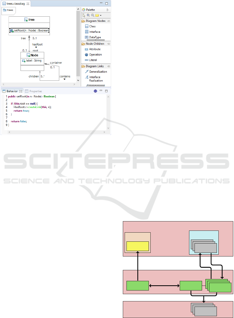
Figure 2: The user interface combining two editors.
body for the selected UML operation in the embedded
ALF editor within the respective view (below).
Xtext provides tool support to embed generated
text editors within SWT composites. If the user clicks
an operation or a derived property within the class di-
agram – in this example, the operation setRoot is se-
lected –, the view is notified about the edit part and
shows the corresponding textual ALF file within the
embedded editor. The ALF operation that is shown
can now be edited textually; apart from behavioral
modeling, also the structural elements relating to the
operation – name, visibility, parameters and docu-
mentation – can be edited. By clicking the button that
is visible within the view, the ALF parsing process as
well as the transformation is induced such that struc-
tural changes of the respective operation get visible
within the class diagram. Thus, the integrated tool
provides roundtrip engineering with respect to struc-
tural elements of the operation; all other structural
model elements are edited within the diagram editor
while behavior can be only edited textually.
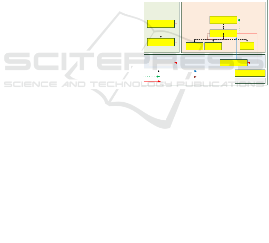
4.2 Overview of the Tool Chain
This section depicts an overview of the technical pro-
cesses running in the background. Figure 3 illustrates
the models within the integrated tool chain and their
relations to each other. It bases upon an underlying
UML model that may comprise requirements, archi-
tecture and implementation artifacts. During analysis
and design, it comprises package and class diagrams,
the latter of which is the starting point for the inte-
gration described in this paper. The class diagram
editor is a projectional editor, i.e., the user modifies
the underlying UML model directly via appropriate
commands and model changes are propagated to the
diagram file.
A bidirectional and incremental model transfor-
mation that is implemented using the BXtend frame-
work converts the UML model to the corresponding
ALF model system and vice versa. The whole UML
model is transformed into a model system that consti-
tutes the corresponding ALF model; thus, editor im-
plementations as scoping and validation as well as the
final code generation can be limited to the ALF model
system only (as it already comprises the correspond-
ing structural counterparts from the UML model).
Since the basic idea of the visual integration within
an integrated user interface is that only ALF opera-
tions are shown within the textual editor, the whole
ALF model is separated into several resources: One
main model – which contains most of the structural
elements and corresponds with the UML model aside
from operation contents – and some branch models
– which comprise apart from some structural ele-
ments concerning the ALF operations all the behav-
ioral model elements not shown by the Valkyrie dia-
gram editors.
Using the Xtext serialization process, text files –
shown by the textual ALF editor – for the ALF branch
models are created. Changes of the ALF text are prop-
agated to the branch models by a parsing process; in
this process, the abstract syntax tree that is built tem-
porary by the Xtext parser is used to store respective
ALF elements permanently within the branch model.
Integrated user interface
Abstract syntax (background)
Fully executable source code
Valkyrie
ALF editor
UML
class diagram
UML
model
ALF
main model
ALF
branch models
ALF
text files
Java
program
GMF
BXtend (M2M)
Acceleo (M2T)
Serializing
(M2T)
Parsing
(T2M)
Figure 3: The tool chain.
Unifying Modeling and Programming with Valkyrie
29
UML ALF
Comment
Element
Class
Operation
Parameter
Class
OperationNode Operation
OperationDefinition
Parameter
ActivityDefinition
DocumentedElement
DocumentationElement
ownerClass
1
*
ownedOperation
1
operation
1
implementation
*
documentation
*
ownedParameter
1
method
1
class
*
ownedOperation
*
ownedParameter
ownedComments
*
isAbstract : Boolean
body : String
isAbstract : Boolean
comment : String
Figure 4: The modified ALF metamodel and corresponding UML elements.
Finally, the code generator that is implemented us-
ing Acceleo creates Java files for the complete ALF
model – including the main model as well as the
branch models; the generated source code is fully ex-
ecutable without requiring any manual code exten-
sions.
4.3 Adaption of the ALF Editor
The stand-alone ALF editor presented in (Buchmann
and Rimer, 2016) provides support for building com-
plete ALF models where the whole model is repre-
sented by a single text file. These models consist of
classes, properties and operations with behavior that
is specified by different kinds of statements which are
contained in activity definitions. In order to enable
tool integration within an integrated user interface, the
ALF metamodel as well as the ALF grammar and fur-
ther editor implementations were modified. Since the
underlying idea for the editing process constitutes that
only the operations and in particular their child ele-
ments are edited within the textual ALF editor, each
ALF document that is shown within the editor only
comprises an operation object.
For this purpose, each operation is stored within
its own model. Figure 4 shows the modified ALF
metamodel subset and corresponding UML meta-
classes; correspondence links are colored red, ALF
metaclasses that are used for main models are col-
ored blue, and those used for branch models are col-
ored brown. Both metaclasses Class as well as Oper-
ation instantiate objects which are used as root objects
within their respective resources. Via an inter-model
cross reference (OperationNode::operation), access
from an ALF main model to its branch models is
achieved. For a UML operation contained in a UML
class, there is an object – an instance of OperationN-
ode – in the main model which constitutes the corre-
sponding ALF object contained in the corresponding
ALF class. The actual structural and behavioral in-
formation about the operation is stored in the branch
models – expressed by structural features of the meta-
class OperationDefinition. All in all, instead of provid-
ing one metaclass for the operation – as it was imple-
mented for the stand-alone ALF editor according to
the official standard –, for technical reasons there are
now three metaclasses and attributes and references
of the original metaclass are distributed among them
without redundancy.
4.4 Bidirectional and Incremental
Model Transformation UML ↔
ALF
The kernel of the tool chain constitutes the model
transformation between UML and ALF models. It is
implemented using the BXtend framework; a phys-
ically persisted correspondence model contains ob-
jects which represent correspondences between UML
and ALF model elements. This transformation is bidi-
rectional: An arbitrary UML model is transformed to
an ALF model system that contains ALF elements ex-
pressing (most of) the semantics of the UML model.
Since ALF only supports a subset of the whole UML
language concepts, some UML elements cannot be
transformed in completely corresponding ALF ele-
ments but an approximation of the semantics ex-
MODELSWARD 2019 - 7th International Conference on Model-Driven Engineering and Software Development
30
UML ALF
: Model
: Class : Class
: Property: Operation
: Parameter
: Parameter
: Operation
: Model
: Package
: Class : Class
: OperationNode : OperationNode : OperationNode
: Operation : Operation : Operation
: OperationDefinition
: Parameter
: Parameter
: OperationDefinition : OperationDefinition
: Parameter
name = trees
name = Tree name = Node
name = setRoot
name = restructure
name = leaf
derived = true
name = node
direction = IN
direction = RETURN
name = trees
name = Tree name = Node
name = setRoot
name = restructure
name = isLeaf
name = node
direction = IN
direction = RETURN
direction = RETURN
ownedParameter
ownedParameter
packagedElement packagedElement
ownedOperation ownedOperation ownedProperty
class
packagedElement
packagedElement packagedElement
owningPackage
ownerClass ownerClass
ownedOperation ownedOperation ownedOperation
operation operation operation
implementation implementation implementation
ownedParameter
ownedParameter
ownedParameter
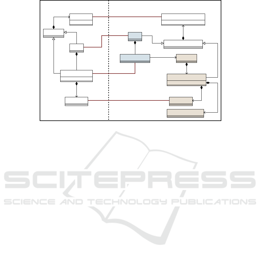
Figure 5: An example UML model and the ALF model system which the UML model is transformed to.
pressed by the UML elements using alternate ALF el-
ements is sought. In contrast, an ALF model system
leads to a UML model that contains elements corre-
sponding to the structural ALF model elements, i.e.,
there are UML model elements for all the ALF model
elements except the activity definitions for the opera-
tions and their child elements.
The transformation works incrementally, i.e. in
case a UML model and a corresponding ALF model
system already exist, model changes are propagated
to the respective opposite model rather than creat-
ing those models from scratch. This is an important
feature to support incremental development processes
that consist of several iterations. On the one hand,
user supplied method bodies have to be retained when
the UML model is transformed; on the other hand,
UML model elements that are referenced by other
models – e.g. in case of GMF, by the diagram file
– may not be replaced.
Table 1: Transformation correspondences of non-fUML el-
ements.
UML model elements ALF model elements
derived property getter operation
readOnly property property + getter operation
interface abstract class
interface realization generalization
The root element of a UML model is an instance
of the metaclass Model; a UML model object corre-
sponds to an instance of the ALF metaclass Model
and an ALF package – i.e., an instance of the ALF
metaclass Package – which is contained in the model
and persists the name of the considered UML model.
UML classifiers – classes, associations, enumera-
tions, and structured data types – as well as enu-
meration literals, generalizations, comments, and or-
dinary properties and operations are transformed to
analogous ALF elements. UML elements which are
not part of the fUML standard have no directly cor-
responding elements but they are mapped otherwise
(see table 1).
Figure 5 depicts an example UML model and its
corresponding ALF model system which constitutes
the target if the model transformation is performed
with the given UML model as the source model. All
involved objects are grouped according to their con-
taining resources. The target model system consists
of one main model – that is marked blue – and three
branch models – that are marked brown; correspon-
dence links are colored red. The branch models rep-
resent the three ALF operations – the corresponding
elements for the two UML operations as well as the
derived UML property – within their own models.
Unifying Modeling and Programming with Valkyrie
31

4.5 Java Code Generation
The final step of the tool chain is the generation of ex-
ecutable Java code from the ALF model system. For
this purpose, the Acceleo framework was used. The
model-to-text transformation tool Acceleo
7
– which
is also used for Valkyrie – allows to express the trans-
formation by templates and queries pretty intuitively
using the Object Constraint Language (OCL) (OMG,
2014). It constitutes a pragmatic implementation of
the MOF Model to Text Transformation Language
(MOFM2T) standard (OMG, 2008). A nice feature of
Acceleo is the integration with Java classes; instead of
expressing the queries exhaustively by OCL expres-
sions, Java methods can be used to build queries by
respective invocation statements. These Java services
were used to get access to other building blocks of the
modeling environment, as e.g., the ALF type system.
For the ALF classifiers, respective Java classes
and interfaces are generated. By access to the branch
models, the body implementations of the ALF oper-
ations are transformed to corresponding Java method
bodies. Functional ALF expressions that cannot be
expressed by completely analogous Java constructs –
e.g., operations for filtering collections – are mapped
to Java operation calls that work on streams. Java
streams
8
– available since Java 1.8 – are sequences
of elements supporting sequential and parallel aggre-
gation operations as filtering and mapping methods.
ALF documentation comments lead to corresponding
Javadoc documentation.
Listing 1 shows some example templates that are
involved when Java code is generated from ALF op-
erations within ALF classes. The first template illus-
trates the call of a method generation template within
the class body template; the respective ALF object
– that contains the structural and behavioral features
of the operation – is accessed by means of the inter-
model cross reference (see line 2). The next template
shows the actual generation of a method for a non-
abstract ALF operation; the template which generates
the included activity definition that contains all the
behavioral model elements for the operation is called
(see line 7). The succeeding template depicts the gen-
eration of the activity definition; if it has a body –
i.e., the operation body is not empty –, the respective
template is called (see line 11). The next template is
called for any block; it consists of statements each of
which is called by an appropriate template (see line
15). Which template is used for an ALF statement
depends on the specific kind of the statement. The
7
https://www.eclipse.org/acceleo/
8
https://docs.oracle.com/javase/8/docs/api/?java/util
/stream/Stream.html
generation of a return statement is shown next: For
the contained expression, an appropriate template is
called (see line 18).
Listing 1: Some Acceleo templates used for the generation
of Java code from the complete ALF model.
1 [template private g ene rat eC l as s Bo dy ( class :
Class ) ]...
2 [for ( op : O per ati onD ef i ni t io n |
owned Op erati on - > c ol lect ( ope ra tio n .
imp lem en t at ion ))]
3 [ g ene ra t eM eth od () /][/for]...[ /template]
4
5 [template public g ene ra teM eth od (
ope rat ion Def ini tio n : O per ati onD efi nit io n )
? ( isA bst ra ct = fa ls e )]
6 [ v is ibi lity . v is i bi lit yGe n ()/]... {
7 [ met ho d . g ene rat e Ac t iv i ty D efi nit ion () /]
8 } [/template]
9
10 [template public g ene rat eAc tiv i ty D ef i ni t ion ( ad
: A cti vi t yD e fi nit ion ) ]
11 [if ( no t _body . ocl IsU nde fi ned ()) ] [ _body .
gen era te Blo ck () /][/if] [/template]
12
13 [template public g ene ra teB loc k ( b : B lo ck )]
14 [for ( st m t : Sta temen t | o wni ng S ta tem ent s ) ]
15 [ g ene rat eSt at e me n t () /] [/for][/ template]
16
17 [template public g ene rat eS t at e me nt ( s ta tem en t :
Ret urn Sta te men t ) ]
18 r eturn [ exp re ssi on . g ene rat eEx pre ssi on () /];[/
template]
19
20 [template public g ene rat eEx pr e ss i on ( e xpr es sio n
: S equ enc eCo nst r uc t io n Exp res sio n ) ]
21 ...[if ( e le ments . o cl AsTyp e (
Seq uen ceE xpr esi onL ist ) . el ements -> is Empty ()
] ne w [ c ol l ect i on I m p l e m e n t a t i on G en () /] < [
typ e N a me . ocl A s T ype ( C o ll e ct i on T y p e R e f e r e n c e
). c hil d R e f . t y p e . typeG e n ( false ) /] > ()
22 [else] S t r eam . of ([ e l e men t s .
ge n er a te S eq u e n c e E l e m e n t s () / ] ) [if (
is O r de r e dS e t () ) ] . di s t i nct () [ /if]. col l e c t (
Col l e ct o r s . to [ ge n er a lC o ll e ct i on K in d () / ] ( ) )
[/if]...[/template]
23
24 [template public g e n e r at e Ex p r e s s i o n ( e xpr e s si o n
: S e q u e n c e E x pa n si o n E x p r e s s i o n ) ]
25 [if ( o p e r at i o n = S e qu e nc e Ex p an s io n Ki n d :: EXIS T S
) ] [ pri m a r y . g en e ra t e E x p r e s si o n () /] . s t r e a m ()
. a n y M atc h ([ v a r iab l e . name /] - > [ ar g u m ent .
ge n e r a t e E x pr e ss i o n () /] )
26 [elseif ... [/if] [ /template]
Also the template that is called for an ALF ex-
pression depends on the type of the expression. The
last two templates demonstrate exemplarily the gen-
eration of Java code for ALF sequence construction
expressions and sequence expansion expressions. Se-
quence construction expressions are mapped to ordi-
MODELSWARD 2019 - 7th International Conference on Model-Driven Engineering and Software Development
32
1
2
3
4
5
6
7
8
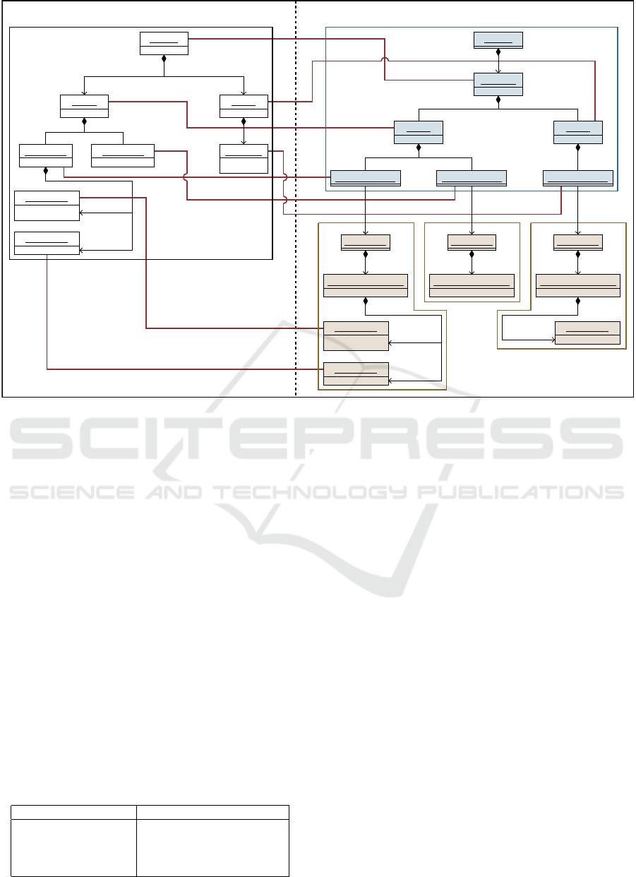
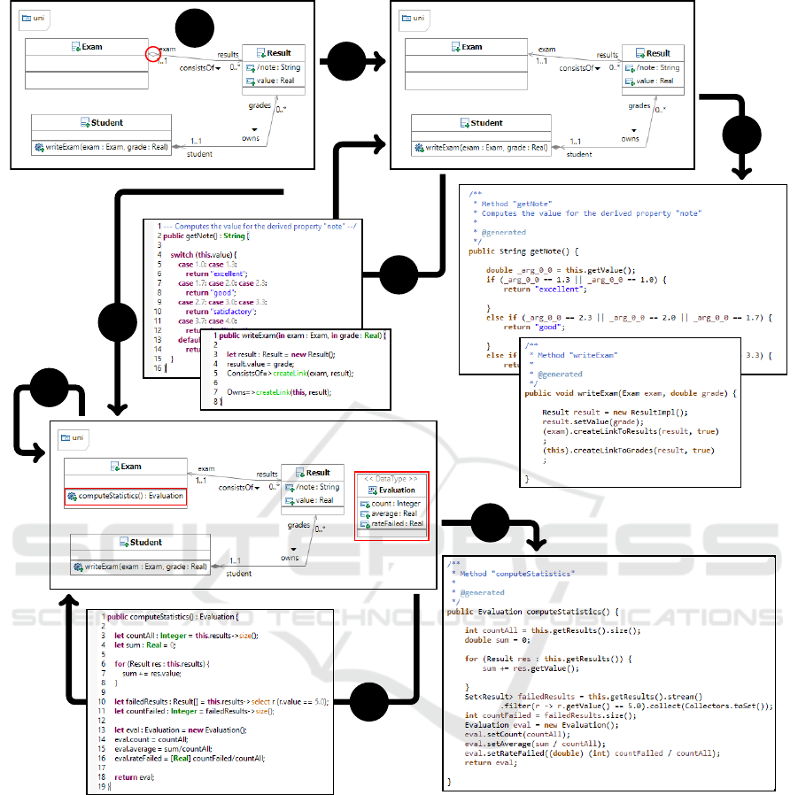
Figure 6: Example development workflow.
nary Java collection creation expressions (see line 21)
– if the created sequence is empty – or Java stream
creation expressions (see line 22) – if the created se-
quence initially has some elements; sequence expan-
sion expressions lead to corresponding method calls
working on streams or collections (see line 25).
5 EXAMPLE
This section illustrates a possible development pro-
cess of an example ALF model that consists of several
iterations of structural as well as behavioral model
evolution. The context of this example is a campus
management system. Figure 6 depicts the workflow.
We start with a UML class diagram (step 1) that con-
sists of three classes and two associations – one com-
position and one aggregation – between them. The
classes contain properties where the class Result has
one derived property. Additionally, the class Student
has an operation. Since aggregations are not part of
the fUML standard, the model does not conform to
the fUML subset and the user is notified by a dialog
message in order to decide whether the transformation
should be performed or not. If the model transforma-
Unifying Modeling and Programming with Valkyrie
33

tion is executed – as we decide for our example –, the
UML elements are modified in order to conform to
the fUML subset; in our example for instance, the as-
sociation is changed such that no association end has
a shared aggregation kind.
While the class diagram contains the structural
model elements, we want to add behavioral artifacts
for the operation and the derived property. By invok-
ing a menu action, the model transformation is exe-
cuted and the ALF model is built (step 2). The UML
operation as well as the derived UML property lead
to ALF operations which can be modified textually
within the specific view. By invoking a button ac-
tion, the ALF model is parsed and the UML model
is updated if structural changes have been performed
(step 3).
The derived property note is supposed to return a
verbal description – ”excellent”, for instance – for the
real attribute value in the Result class. In our exam-
ple, we use an ALF switch statement which is more
powerful than the respective Java statement, as we use
a real argument value for the switch. The operation
writeExam is supposed to create a new result object
with the values that are given by the parameters. In
our example, we use ALF link operation expressions
to create the links.
At the end of the current iteration, Java code is
generated from the ALF model (step 4). This is also
induced by a menu action. The generated Java pack-
age has one class and one interface for each ALF
class. For the ALF operations – i.e., for the ALF op-
eration that corresponds to the UML operation as well
as the ALF operation resulted from the derived UML
property – Java methods are generated. Since Java
cannot express the ALF switch statement as an analo-
gous Java switch statement, if statements are used.
Now, we want to modify the model (step 5).
Within the class diagram, a new data type is created; it
is used for bundling statistical information. The class
Exam gets a new operation for computing statistical
information about the results which is returned as an
instance of the new data type. After that we invoke
the incremental model transformation such that the
structural changes are propagated to the ALF model
(step 6).
Within the ALF operation that emerged from the
new UML operation, we use sequence operation ex-
pressions – e.g., for the computation of the count
value –, a for statement – during the computation pro-
cess for the average value –, and a sequence expan-
sion expression – to get the subset of failed results
which is needed for the rateFailed value (step 7).
Finally, Java code for the modified ALF model
is generated (step 8). The sequence expressions are
mapped to operation calls to Java collections and
streams.
6 DISCUSSION
In this section, the modeling environment described
above is discussed. First, the benefits of the environ-
ment are explicated.
Convenient Notation. The integrated tool chain pro-
vides modeling structure and behavior by combin-
ing two different paradigms of editing models as
well as two different modeling languages. Within
the projectional diagram editor, structural model
elements can be modeled pretty conveniently by
class diagrams using graphical elements. Further-
more, the structure is augmented by behavioral
elements which are specified textually within a
parser-based editor instead of also using graphical
diagrams as activity diagrams – where the repre-
sentation of the control flow can get very complex
and confusing. ALF provides a precise and in-
tuitive syntax which allows for modeling widely
ramified control flows clearly and intuitively.
Fully Executable Models. A major problem of sev-
eral behavioral UML diagrams is that they of-
ten lack a well-defined execution semantics. Not
only providing a precise and intuitive syntax, ALF
comes along with a well-defined execution se-
mantics. Since the structure as well as the behav-
ior of the models are specified, the code genera-
tor creates fully executable Java programs where
no further user interaction as augmenting the final
code is required.
Visual Integration. The integration of UML and
ALF is performed not only conceptually and tech-
nically but also visually: The different editors
that are involved in the modeling environment are
combined visually within an integrated user in-
terface using appropriate Eclipse concepts. Al-
though several models are called in the back-
ground, the user gets the feeling of editing one
model.
Flexible Workflow. The kernel transformation is
bidirectional and incremental. Thus, a very flexi-
ble and incremental workflow is supported that fa-
cilitates a development process consisting of sev-
eral iterations.
The aforementioned benefits emphasize the pos-
itive aspects of using ALF to express behavioral ele-
ments. However, we have to reveal a significant draw-
back: Although ALF is able to express a quite large
MODELSWARD 2019 - 7th International Conference on Model-Driven Engineering and Software Development
34

range of model components, only a proper subset of
the UML standard is supported; thus, some UML se-
mantics – as interfaces – cannot be expressed exactly.
Nevertheless, by using alternate ALF components –
e.g., abstract classes instead of interfaces –, the se-
mantics can often be approximated pretty well such
that in practice, the consequences concerning limited
expressiveness do not restrict the development pro-
cess too much.
7 CONCLUSION
In this paper, we introduced our approach to integrate
two model editors based on different paradigms: A
projectional editor for UML diagrams and a parser-
based editor for ALF text. The resulting tool chain
supports the creation of fully executable models based
on both specifications and allows for the generation of
Java source code. Since it relies on official standards
– UML (OMG, 2015b) and ALF (OMG, 2013a) –,
compatibility with other CASE tools is ensured. The
integrated environment provides benefits for the mod-
eler in terms of providing different views on the un-
derlying models, e.g. class diagrams for the structural
parts and ALF textual specifications for the behav-
ioral parts of method implementations. Consequently,
the modeler always works on the right level of ab-
straction and uses the most appropriate formalism.
REFERENCES
Buchmann, T. (2012). Valkyrie: A UML-Based Model-
Driven Environment for Model-Driven Software En-
gineering. In Proceedings of the 7th International
Conference on Software Paradigm Trends (ICSOFT
2012), pages 147–157, Rome, Italy. SciTePress.
Buchmann, T. (2017). Prodeling with the action language
for foundational UML. In Damiani, E., Spanoudakis,
G., and Maciaszek, L. A., editors, ENASE 2017 -
Proceedings of the 12th International Conference on
Evaluation of Novel Approaches to Software Engi-
neering, Porto, Portugal, April 28-29, 2017., pages
263–270. SciTePress.
Buchmann, T. (2018). Bxtend - A framework for (bidi-
rectional) incremental model transformations. In
Hammoudi, S., Pires, L. F., and Selic, B., edi-
tors, Proceedings of the 6th International Confer-
ence on Model-Driven Engineering and Software De-
velopment, MODELSWARD 2018, Funchal, Madeira
- Portugal, January 22-24, 2018., pages 336–345.
SciTePress.
Buchmann, T. and Rimer, A. (2016). Unifying Modeling
and Programming with ALF. In Kaindl, H. and Meli,
R., editors, Proceedings of the 2nd International Con-
ference on Advances and Trends in Software Engi-
neering (SOFTENG 2016), page 6. IARIA.
Buchmann, T. and Schw
¨
agerl, F. (2015). On A-posteriori
Integration of Ecore Models and Hand-written Java
Code. In Pascal Lorenz, M. v. S. and Cardoso, J.,
editors, Proceedings of the 10th International Con-
ference on Software Paradigm Trends, pages 95–102.
SciTePress.
Buchmann, T. and Westfechtel, B. (2016). Using Triple
Graph Grammars to Realize Incremental Round-Trip
Engineering. IET Software. Online first, http://digital-
library.theiet.org/content/journals/10.1049/iet-
sen.2015.0125.
Buchmann, T., Westfechtel, B., and Winetzhammer, S.
(2011). The added value of programmed graph trans-
formations - A case study from software configura-
tion management. In Sch
¨
urr, A., Varr
´
o, D., and Varr
´
o,
G., editors, Applications of Graph Transformations
with Industrial Relevance - 4th International Sympo-
sium, AGTIVE 2011, Budapest, Hungary, October 4-
7, 2011, Revised Selected and Invited Papers, volume
7233 of Lecture Notes in Computer Science, pages
198–209. Springer.
Guermazi, S., Tatibouet, J., Cuccuru, A., Seidewitz, E.,
Dhouib, S., and G
´
erard, S. (2015). Executable mod-
eling with fuml and alf in papyrus: Tooling and ex-
periments. In Mayerhofer, T., Langer, P., Seide-
witz, E., and Gray, J., editors, Proceedings of the 1st
International Workshop on Executable Modeling co-
located with ACM/IEEE 18th International Confer-
ence on Model Driven Engineering Languages and
Systems (MODELS 2015), Ottawa, Canada, Septem-
ber 27, 2015., volume 1560 of CEUR Workshop Pro-
ceedings, pages 3–8. CEUR-WS.org.
Lethbridge, T. C., Forward, A., and Badreddin, O. (2010).
Umplification: Refactoring to incrementally add ab-
straction to a program. In Reverse Engineering
(WCRE), 2010 17th Working Conference on, pages
220–224. IEEE.
Mellor, S. J., Kendall, S., Uhl, A., and Weise, D. (2004).
MDA Distilled. Addison Wesley Longman Publishing
Co., Inc., Redwood City, CA, USA.
OMG (2008). MOF Model to Text Transformation Lan-
guage, v1.0. OMG, Needham, MA, formal/2008-01-
16 edition.
OMG (2013a). Action Language for Foundational UML
(ALF). Object Management Group, Needham, MA,
formal/2013-09-01 edition.
OMG (2013b). Semantics of a Foundational Subset for Ex-
ecutable UML Models (fUML). Object Management
Group, Needham, MA, formal/2013-08-06 edition.
OMG (2014). Object Constraint Language. OMG, Need-
ham, MA, formal/2014-02-03 edition.
OMG (2015a). Meta Object Facility (MOF) Version 2.5.
OMG, Needham, MA, formal/2015-06-05 edition.
OMG (2015b). Unified Modeling Language (UML). Object
Management Group, Needham, MA, formal/15-03-01
edition.
Steinberg, D., Budinsky, F., Paternostro, M., and Merks,
E. (2009). EMF Eclipse Modeling Framework. The
Eclipse Series. Addison-Wesley, Boston, MA, 2nd
edition.
Unifying Modeling and Programming with Valkyrie
35

The Fujaba Developer Teams from Paderborn, Kassel,
Darmstadt, Siegen and Bayreuth (2005). The Fujaba
Tool Suite 2005: An Overview About the Develop-
ment Efforts in Paderborn, Kassel, Darmstadt, Siegen
and Bayreuth. In Giese, H. and Z
¨
undorf, A., editors,
Proceedings of the 3rd international Fujaba Days,
pages 1–13.
V
¨
olter, M., Stahl, T., Bettin, J., Haase, A., and Helsen, S.
(2006). Model-Driven Software Development: Tech-
nology, Engineering, Management. John Wiley &
Sons.
MODELSWARD 2019 - 7th International Conference on Model-Driven Engineering and Software Development
36
