Avoiding Glare by Controlling the Transmittance of Incident Light
Takeharu Kondo, Fumihiko Sakaue and Jun Sato
Nagoya Institute of Technology, Nagoya 466-8555, Japan
Keywords:
Anti-glare, Windshield, Transmittance, GAN.
Abstract:
In this paper, we introduce a new method for enhancing the visibility of human vision. In particular we propose
a method for avoiding glare caused by strong incident light, such as sunlight and headlight of oncoming
vehicles, in driving situations. Our method controls the transmittance of incident light pixel by pixel according
to the power of the incident light. For computing the transmittance of light efficiently from camera images, we
propose a leaning based method utilizing a generative adversarial network (GAN). By using our method, the
visibility of drivers can be improved drastically, and objects in dark place become visible even under strong
backlight, such as sunlight and headlight of oncoming vehicles.
1 INTRODUCTION
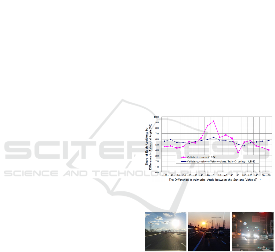
As shown in the statistics of traffic accidents in Fig. 1,
serious accidents increase drastically when the rela-
tive angle between the sun and the driver’s viewing di-
rection becomes small (Hagita and Mori, 2013). This
is because the dynamic range of the entire scene be-
comes very large under the existence of backlight as
shown in Fig. 2, and the visibility of objects in dark
place is greatly deteriorated because of the limited dy-
namic range of human vision. Furthermore, since the
dark adaptation takes much more time than the bright
adaptation in human vision, the strong backlight, such
as sunlight and headlight of oncoming vehicles, cau-
ses invisibility for a long time in human vision. The-
refore, it is very important to improve driver’s visibi-
lity in such high contrast situations.
Thus, we in this paper introduce a new method
for enhancing the visibility of human vision by di-
rectly controlling the incident light on human eyes.
In particular, we propose a method for controlling
the transmittance of glass pixel by pixel according to
the power of incident light. For this objective, we
capture the intensity of incident light by using a ca-
mera. However, the intensity of light observed by a
camera is often saturated because of the high power
incident light such as sunlight and headlight as shown
in Fig. 2. Thus, for computing the transmittance of in-
cident light efficiently from saturated camera images,
we propose a leaning based method utilizing a gene-
rative adversarial network (GAN) (Goodfellow et al.,
2014). GAN is a very successful neural network,
Figure 1: The relationship between the car accident rate and
the relative angle between the sun and the viewing direction
of driver (Hagita and Mori, 2013).
Figure 2: High contract scenes caused by the backlight of
sunlight and headlight of oncoming vehicles.
and many variations have been proposed in recent ye-
ars (Radford et al., 2016; Isola et al., 2017; Zhu et al.,
2017). In this paper, we propose a conditional GAN
for generating transmittance images efficiently from
saturated camera images. Our conditional GAN le-
arns ideal light intensity for driver’s vision, and ge-
nerates transmittance images for providing ideal light
intensity to drivers.
By using our method, the visibility of drivers can
be improved drastically, and objects such as pedestri-
Kondo, T., Sakaue, F. and Sato, J.
Avoiding Glare by Controlling the Transmittance of Incident Light.
DOI: 10.5220/0007256800190026
In Proceedings of the 14th International Joint Conference on Computer Vision, Imaging and Computer Graphics Theory and Applications (VISIGRAPP 2019), pages 19-26
ISBN: 978-989-758-354-4
Copyright
c
2019 by SCITEPRESS – Science and Technology Publications, Lda. All rights reserved
19

ans in dark place become visible, even if the incident
light includes strong backlight, such as sunlight and
headlight of oncoming vehicles.
2 RELATED WORK
In computer vision, many methods have been propo-
sed for producing high dynamic range (HDR) ima-
ges from low dynamic range (LDR) images (Mann
and Picard, 1995; Debevec and Malik, 1997). These
methods combine multiple static images taken un-
der different exposure time. To extend these met-
hod for dynamic scenes, the optical flow estimation
was also combined with HDR methods (Tomaszew-
ska and Mantiuk, 2007; Kalantari and Ramamoorthi,
2017; Wu, et al., 2018). For obtaining HDR images
from single shot imaging, coded exposure techniques
have been proposed (Schedl et al., 2013). More re-
cently, variable exposure imaging, which controls ex-
posure time pixel by pixel, has also been proposed
and used for generating HDR images from single shot
imaging (Uda et al., 2016). These single shot methods
provide us better HDR images under dynamic scenes.
Although these methods enable us to improve the
quality of images taken by cameras, the generated
HDR images are not directly visible for human ob-
servers, and these HDR images must be transfor-
med to LDR images again by using some tone map-
ping functions before showing them to human obser-
vers (Reinhard et al., 2002). As a result, these infor-
mation pipelines are not so efficient when we want to
show high quality images to observers. Thus, we in
this paper consider a direct improvement of light in-
cident on the human observers. In particular, we con-
sider a method for improving the visibility of human
drivers on the road.
Some countermeasures have been taken for im-
proving the visibility of vehicle drivers by directly
controlling light. For example, at the entrance and
the exit of tunnels, the light is strengthened for urging
the bright adaptation and dark adaptation of drivers
vision (CIE, 2004). Also on the vehicle side, automa-
tic anti-glare mirrors (GENTEX) have been realized,
which automatically adjust the amount of reflected
light according to the magnitude of incident light. Re-
cently, dimmable windows which block sunlight and
heat have also been developed (SmaerGlass).
However, these anti-glare systems change the re-
flectance or transmittance of entire mirrors or win-
dows uniformly. Therefore, if an intense light is inci-
dent on a part of the mirror or the window, the entire
mirror or the entire window becomes dark, and dark
objects in the scene become invisible. If it is a mirror,
this is not a big problem, but in the case of winds-
hields, it is very dangerous to darken all the winds-
hield surface.
For shutting out specific incoming light selecti-
vely, the polarization is often used. For example, if
we put polarized glass in front of an observer, and
if we emit polarized light from the headlamp of the
vehicle, whose polarization is rotated 90 degrees from
the polarization of the observer, then the light from
the headlamp can be shut out selectively in the ob-
served light (Land, 1948). Although the polarization
can eliminate specific light efficiently, it can be used
only for artificial light or specific natural light such as
reflected light, and it cannot control the intensity of
arbitrary incident light with arbitrary amount.
Thus, in this paper, we propose a method for con-
trolling the transmittance of light pixel by pixel, so
that strong incident light such as sunlight and head-
light of other vehicles is weaken, and weak incident
light of dark place is transmitted as it is.
3 OPTICAL ADAPTATION IN
HUMAN VISION
In general, when the human eye moves from a bright
place to a dark place, the lowest observable brightness
of vision decreases making proper observation possi-
ble even in dark places. This is called dark adaptation,
and the human vision which completed the dark adap-
tation is called scotopic vision. On the other hand,
when we move from a dark place to a bright place, the
highest observable brightness of vision rises, and the
lowest observable brightness also rises. As a result,
bright scenery can be observed by the human vision.
This process is called bright adaptation, and the hu-
man vision which completed the bright adaptation is
called photopic vision.
In general, the bright adaptation finishes in 30 se-
conds, whereas the dark adaptation takes about 30
minutes. Therefore, once the human vision changes
to the photopic vision from the scotopic vision by a
strong incident light, it cannot return to the scotopic
vision easily.
At dusk, the human vision is in an intermediate
state between photopic vision and scotopic vision,
which is called mesopic vision. When bright sun-
light enters the human eyes in mesopic vision state,
the light adaptation occurs, and the state changes from
the mesopic vision to the photopic vision. Once the
state is changed to the photopic vision, it cannot re-
turn to the mesopic vision easily, and the visibility of
dark places is degraded for long time. As a result, the
drivers cannot see pedestrians and obstacles at dusk,
VISAPP 2019 - 14th International Conference on Computer Vision Theory and Applications
20
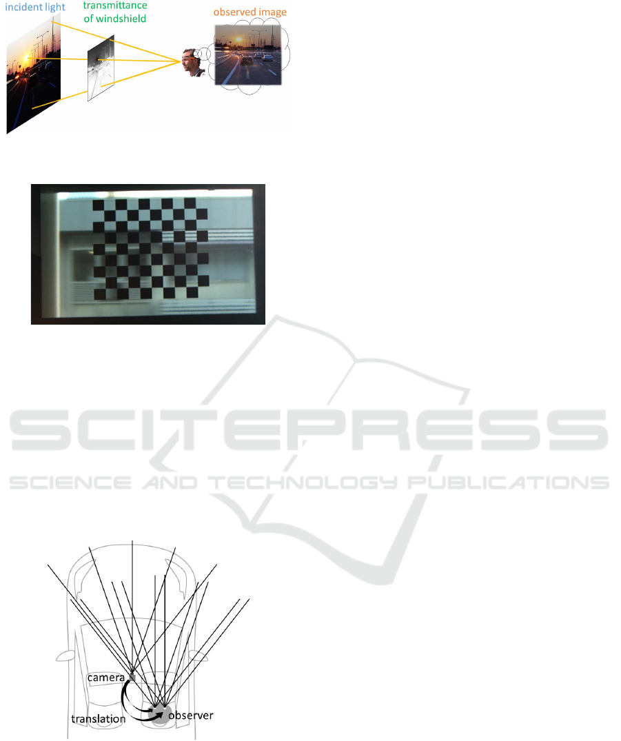
Figure 3: Controlling the transmittance of windshield pixel
by pixel according to the incident light.
Figure 4: Controlling the transmittance of windshield pixel
by pixel by using a LCD panel.
and the possibility of serious car accidents increases.
Thus, in this paper, we control the transmittance
of windshield pixel by pixel, so that strong incident
light such as sunlight and headlight of other vehicles
is weaken, and weak incident light of dark place is
transmitted as it is, as shown in Fig. 3. By controlling
the transmittance of the windshield like this, the sco-
topic vision and the mesopic vision can be preserved
at night and dusk, and the drivers can recognize pede-
strians and obstacles even under strong backlight.
Figure 5: Incident light of camera and incident light of ob-
server. Since the depth of background scene is very large
comparing with the distance between the camera and the
observer, we can assume that the incident light at the camera
viewpoint and the incident light at the observer’s viewpoint
are parallel to each other.
4 CONTROLLABLE
WINDSHIELD
Unfortunately, there is no glass material which can
control its transmittance pixel by pixel. Thus, we in
this research combine a liquid crystal display panel
(LCD) with a glass, so that the transmittance of each
pixel of the glass can be controlled.
Suppose an incident light with the magnitude of E
i
goes though the i-th pixel of the LCD and comes into
the eye of the observer. Then, the observed intensity
I
i
can be described as follows:
I
i
= E
i
α
i
(1)
where, α
i
is the transmittance of i-th pixel of the LCD.
Fig. 4 shows the observed intensity through an
LCD when we set a transmittance image of checker
pattern to the LCD. As we can see in this image, in-
cident light rays at black pixels are blocked, and only
background scene at white pixels is visible.
For controlling the transmittance of the winds-
hield for an observer, we need the incident light image
at the viewpoint of the observer, i.e. the intensity of
incident light in all the orientation at the viewpoint.
For obtaining the incident light image, we use a ca-
mera fixed near the observer as shown in Fig. 5. Alt-
hough the viewpoints of the camera and the obser-
ver are different, we can generate the incident light
image of the observer from that of the camera just by
translating the image. This is because the depth of the
background scene is very large comparing with the
distance between the camera and the observer and we
can assume that the incident light at the camera view-
point and the incident light at the observer’s viewpoint
are parallel to each other as shown in Fig. 5. Thus, by
using the camera image, we can compute the trans-
mittance image at each viewpoint of the observer.
5 COMPUTING
TRANSMITTANCE BY USING
GENERATIVE ADVERSARIAL
NETWORK
The naive method for controlling the transmittance of
the windshield is to simply cut the high intensity part
in the observed incident light image. However, this
is not a good method for several reasons. Firstly, the
high intensity part in the observed camera image is
often saturated because of the high power of incident
light, such as sunlight and headlight, and thus its ac-
tual intensity E
i
cannot be obtained. Secondly, there
seems to be a better way to control the transmittance
Avoiding Glare by Controlling the Transmittance of Incident Light
21
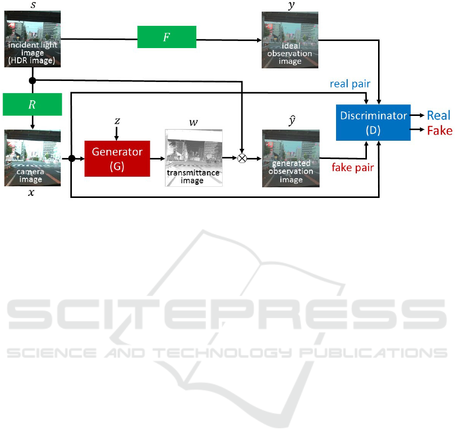
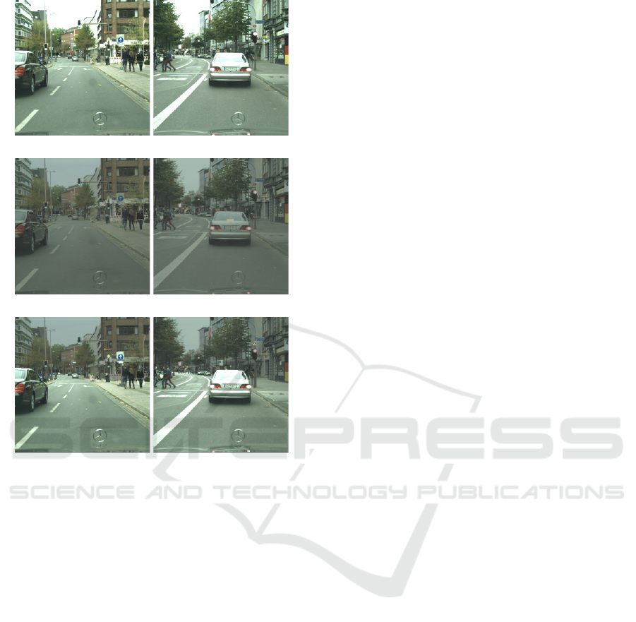
Figure 6: Generative adversarial network (GAN) for generating transmittance images. Generator, G, produces a transmittance
image, w, from a camera image x. Then, it is multiplied with the incident light image, s, and produces an observation image,
ˆy. The discriminator, D, trains so that it can distinguish real and fake pairs of camera image and observation image correctly.
On the other hand, the generator, G, trains so that it minimizes correct answer of discriminator.
for enhancing the visibility of the scene. For exam-
ple, it may be useful if we can enhance the visibility
of pedestrians selectively.
Thus, we in this paper control the transmittance
of LCD by using deep learning. In particular, we use
Generative Adversarial Network (GAN) (Goodfellow
et al., 2014) for generating visually pleasant intensity
image after controlling the transmittance of incident
light. In this research, we use conditional GAN (Isola
et al., 2017), and generate transmittance images, i.e.
LCD images, from input camera images which are sa-
turated partially because of high power incident lig-
hts, such as sun and headlight.
The network structure of our conditional GAN is
as shown in Fig. 6. The generator G is a 16-layer
convolution-deconvolution network (U-Net) (Ronne-
berger et al., 2015) and the discriminator D is an 8-
layer convolution network. We represent high power
incident light by an HDR image s, and consider that
a camera image x is generated from the HDR image s
through a camera response function R as follows:
x = R(s) (2)
Since the camera image x generated from the response
function R is a low dynamic range image, the camera
image x is saturated if we have strong incident light.
The generator generates a transmittance image w,
i.e. LCD image, from the saturated camera image x
as follows:
w = G(x, z) (3)
where, z denotes a random noise vector.
Then, an observation image ˆy is computed by mul-
tiplying the high dynamic incident light image s with
the transmittance image w obtained from the genera-
tor as follows:
ˆy = s ⊗ w
= s ⊗ G(x, z) (4)
where, ⊗ denotes a pixel-wise multiplication.
We also compute ideal observation image y from
the high dynamic incident light image s by using a
tone mapping function F as follows:
y = F(s) (5)
Then, a pair of saturated camera image and the
observation image, {x, y} or {x, ˆy}, is given to the dis-
criminator, and the discriminator judges whether the
pair is given from the ideal observation image y or the
observation image ˆy computed from the transmittance
w generated by the generator.
The network is trained, so that the discriminator
maximizes the rate of correct judgments and the ge-
nerator minimizes it. Thus, the training of our condi-
tional GAN can be described as follows:
G
∗
= argmin
G
max
D
L
cGAN
(G, D) + λL
L1
(G) (6)
where, L
cGAN
is the following adversarial loss:
L
cGAN
(G, D) = E
x,y∼p
data
(x,y)
[logD(x, y)] +
E
x∼p
data
(x),z∼p
z
(z)
[log(1 − D(x, s ⊗G(x, z)))] (7)
and L
L1
is an L
1
loss as follows:
L
L1
(G) = E
x,y∼p
data
(x,y),z∼p
z
(z)
[∥y − s ⊗ G(x, z)∥
1
](8)
VISAPP 2019 - 14th International Conference on Computer Vision Theory and Applications
22
(a) camera image
(b) ideal observation image from F
1
(c) ideal observation image from F
2
Figure 7: Examples of camera images and ideal observa-
tion images generated by using F
1
and F
2
as tone mapping
functions in our training data set. The camera images are
saturated, while the ideal observation images are not satu-
rated. However, the visibility of pedestrians, vehicles, road
markers and road signs is degraded in ideal observation ima-
ges generated from F
1
, while the visibility of those in F
2
is
preserved.
At the initial stage of the training, the discrimi-
nator can easily identify the fake observation images,
but gradually it becomes difficult to identify the fake
images, and at the final stage of the training the ge-
nerator can generate transmittance images for gene-
rating visually pleasant observation images for obser-
vers.
The proposed method can generate ideal transmit-
tance images for LCD control, even if the input ca-
mera images are partially saturated. Furthermore, the
ideal observation image can be designed freely by
modifying the tone mapping function F. For exam-
ple we can emphasize vehicles and pedestrians in the
ideal observation images by designing the tone map-
ping functions according to the objects in the scene.
In the next section, we consider the design of tone
mapping function F.
6 DESIGNING TONE MAPPING
FUNCTIONS
In this research, we consider two different types of
tone mapping functions.
The first one is a simple tone mapping function
F
1
(s) proposed by Reinhard et al. (Reinhard et al.,
2002), which is often used as a standard tone map-
ping function, where s denotes the intensity of inci-
dent light image.
The second one is a tone mapping function, which
varies according to the object in the scene. For emp-
hasizing pedestrians, vehicles, road and road signs
in the scene, we define the following tone mapping
function, F
2
(s):
F
2
(s) =
{
s : pedestrians, vehicles, road, road signs
F
1
(s) : others
(9)
By using this function, we can preserve the intensity
of pedestrians, vehicles, road and road signs, while
the intensity of others decreases according to Rein-
hard’s tone mapping function.
7 DATA SET AND TRAINING
For training our network, we need high dynamic in-
cident light images, s, and their camera images, x,
considering the camera response function, R. In this
research, we generated camera images, x, by simply
cropping the intensity of the high dynamic incident
light images, s. We also generated ideal observation
images, y, from high dynamic incident light images,
s, by using tone mapping functions, F
1
and F
2
, des-
cribed in section 6. We made 2974 sets of training
data from images in Cityscapes dataset (Cityscapes).
The annotation in Cityscapes dataset was used in F
2
function.
Fig. 7 shows some examples of our training data.
Fig. 7 (a) shows camera images, Fig. 7 (b) shows ideal
observation images made by using F
1
as a tone map-
ping function, and Fig. 7 (c) shows those made by
using F
2
. As we can see in these images, the ideal ob-
servation images are not saturated, while the camera
images are saturated at high intensity part, such as fa-
raway buildings. However, the visibility of pedestri-
ans, vehicles, road and road signs is degraded in ideal
observation images generated from F
1
. On the con-
trary, the visibility of those in F
2
is preserved. We
trained our network by using these training data with
100 epochs.
Avoiding Glare by Controlling the Transmittance of Incident Light
23
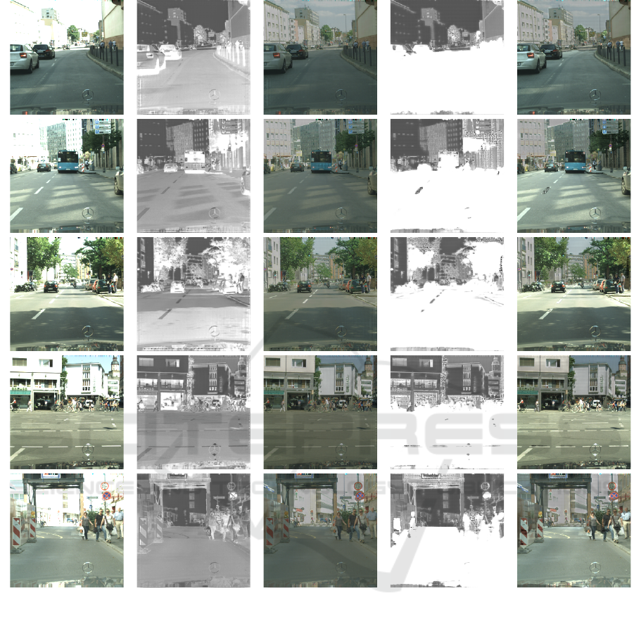
(a) camera image (b) transmittance (c) observed (d) transmittance (e) observed
image of F
1
image of F
1
image of F
2
image of F
2
Figure 8: Our results from test data. Column (a) shows input camera images, and column (b) shows transmittance images
generated from our network trained by using F
1
as a tone mapping function. Column (c) shows images observed by using
transmittance images in column (b). Column (d) and (e) show those obtained by using our network trained by using F
2
as a
tone mapping function. As show in (c) and (e), both networks generated transmittance images properly, so that the observed
images do not suffer from saturation unlike input camera images in (a). However, the visibility of pedestrians, road signs and
vehicles is degraded in the observed images in (c), while the visibility of those objects is preserved in the observed images in
(e).
8 EXPERIMENTS
We next show the experimental results obtained by
using F
1
and F
2
as tone mapping functions.
The first column (a) in Fig. 8 shows input camera
images which are not included in the training data
sets. As we can see in these images the intensity of
faraway buildings is saturated, and some buildings are
not visible because of the heavy saturation.
The column (b) in Fig. 8 shows transmittance ima-
ges obtained from the generator trained by using F
1
data set. As shown in these images, the transmittance
was generated so that the incident light at high inten-
sity part is suppressed and the incident light at low
VISAPP 2019 - 14th International Conference on Computer Vision Theory and Applications
24
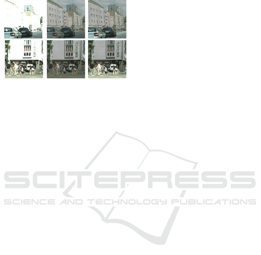
!
camera image F
1
F
2
Figure 9: Comparison of the tone mapping functions, F
1
and F
2
, used in the training step of our network. Both F
1
and F
2
enable us to see faraway buildings and their details,
which are not visible in the original camera images. Howe-
ver, the visibility of pedestrians is degraded in F
1
, while that
is preserved in F
2
.
intensity part is preserved. The column (c) in Fig. 8
shows observed images obtained after transmittance
control based on Fig. 8 (b). As shown in these ima-
ges, the observed images are not saturated unlike ca-
mera images in Fig. 8 (a), and the detail of faraway
buildings is clearly visible. However, the intensity of
all over the image is decreased in (c), and as a result,
the visibility of important objects, such as pedestrians
and road signs, is degraded in Fig. 8 (c).
Fig. 8 (d) shows transmittance obtained from our
generator trained by using F
2
data set, and Fig. 8 (e)
shows images observed after applying transmittance
images in Fig. 8 (d). As shown in (e), our network
trained by F
2
provides clear view of pedestrians, vehi-
cles, road and road signs, while the detail of faraway
buildings is also visible. The transmittance images
in column (d) also show these properties, that is the
transmittance of pedestrians, vehicles, road and road
signs is very high, while that of faraway buildings and
sky is low as shown in (d).
The magnified images in Fig. 9 compares the vi-
sibility of buildings and pedestrians in the observed
images derived from our network trained by F
1
and
F
2
. As shown in this figure, both F
1
and F
2
enable us
to see the detail of buildings, which is not visible in
the original camera images. However, the visibility of
pedestrians is degraded in F
1
based method, while the
F
2
based method preserves their visibility.
From these results, we find that our direct control
of incident light is very efficient for human observers
to see high dynamic scenes caused by backlight, etc.
We also find that the transmittance computed from F
2
provides us higher visibility of important objects in
the scene than the standard tone mapping functions.
9 CONCLUSION
In this paper, we proposed a method for avoiding glare
caused by strong incident light, such as sunlight and
headlight, in driving situations.
Our method controls the transmittance of winds-
hield pixel by pixel according to the intensity of inci-
dent light. For computing the transmittance of glass
efficiently from saturated camera images, we propo-
sed a method based on a generative adversarial net-
work (GAN).
In our method, the ideal observation images of the
driver can be designed freely. Therefore, we can emp-
hasize the intensity of specific objects, such as pede-
strians, in the driver’s view.
By using our method, the visibility of drivers can
be improved drastically, and objects such as pedestri-
ans in dark place become visible even under strong
backlight of sun, etc.
REFERENCES
Hagita, K., Mori, K.: Analysis of the Influence of Sun Glare
on Bicycle or Pedestrian Accidents with Turning Vehi-
cle, World Conference on Transport Research, 2013.
Goodfellow, I., Pouget-Abadie, J., Mirza, M., Xu, B.,
Warde-Farley, D., Ozair, S., Courville, A. and Bengio,
Y.: Generative Adversarial Nets, Advances in Neural
Information Processing Systems, 2672–2680, 2014.
Isola, P., Zhu, J.-Y., Zhou, T. and Efros, A. A.: Image-
to-image translation with conditional adversarial net-
works, IEEE Conference on Computer Vision and Pat-
tern Recognition, 2017.
Ronneberger, O., Fischer, P. and Brox, T.: U-Net: Convolu-
tional Networks for Biomedical Image Segmentation,
International Conference on Medical Image Compu-
ting and Computer-assisted Intervention, Springer,
pp. 234–241, 2015.
Radford, A., Metz, L., Chintala, S.: Unsupervised Repre-
sentation Learning with Deep Convolutional Genera-
tive Adversarial Networks, International Conference
on Learning Representations, 2016.
Zhu, J.Y., Park, T., Isola, P., Efros, A.A.: Unpaired Image-
to-Image Translation using Cycle-Consistent Adver-
sarial Networkss, IEEE International Conference on
Computer Vision, 2017.
Mann, S., Picard, R.W.: On Being ‘undigital’ With Digital
Cameras: Extending Dynamic Range By Combining
Differently Exposed Pictures, IS & T, 1995.
Debevec, P., Malik, J.: Recovering High Dynamic Range
Radiance Maps from Photographs, SIGGRAPH, 1997.
Tomaszewska, A., Mantiuk, R.: Image Registration for
Multi-exposure High Dynamic Range Image Acqui-
sition, WSCG, 2007.
Avoiding Glare by Controlling the Transmittance of Incident Light
25

Kalantari, N.K., Ramamoorthi, R.: Deep high dynamic
range imaging of dynamic scenes, ACM Transaction
on Graphics, 2017.
Wu, S., Xu, J., Tai, Y.W., Tang, C.K.: Deep High Dyna-
mic Range Imaging with Large Foreground Motions,
ECCV, 2018.
Schedl, D.C., Birklbauer, C., Bimber, O.: Coded exposure
HDR light-field video recording, SIGGRAPH, 2013.
Uda, S., Sakaue, F., Sato, J.: Variable exposure time ima-
ging for obtaining unblurred HDR images, IPSJ Tran-
sactions on Computer Vision and Applications, 2016.
CIE, Guide for the Lighting of Road Tunnels and Under-
passes; CIE Publication, Vol 88, 2004.
GENTEX, http://www.gentex.com/
SmartGlass, http://www.smartglass.com/
Land, E.H.: The Polarized Headlight System, Annual Con-
ference of the Highway Research Board, 1–20, 1948.
Reinhard, E., Stark, M., Shirley, P., Ferwerda, J.: Photo-
graphic Tone Reproduction for Digital Images, SIG-
GRAPH, 2002.
Cityscapes Dataset, https://www.cityscapes-dataset.com/
VISAPP 2019 - 14th International Conference on Computer Vision Theory and Applications
26
