
Symmetry-aware Registration of Human Faces
Martin Prantl, Libor V
´
a
ˇ
sa and Ivana Kolingerov
´
a
NTIS - New Technologies for the Information Society, Faculty of Applied Sciences, University of West Bohemia,
Technicka 8, Pilsen, Czech Republic
Keywords:
Registration, Symmetry, Computer Graphics.
Abstract:
Registration of 3D objects is a challenging task, especially in presence of symmetric parts. A registration
algorithm based on feature vectors must be able to distinguish left and right parts. Symmetric geometry can
be found in those two parts, however, most popular feature vectors produce equal numbers in this case, even
though the geometry is in fact different. One field, where this problem arises, is the registration of partially
overlapping parts of human faces or entire heads. The symmetric parts in this case are often eyes, ears, nostrils,
mouth corners etc. Using symmetry-oblivious feature vectors makes it hard to distinguish left and right part of
the face or head. This paper presents a feature vector modification based on a vector field flux and curvature.
Results show that the modified feature vector can improve the subsequent registration process.
1 INTRODUCTION
Global registration of partially overlapping parts of
the same model is a well-known problem in the field
of computer graphics and geometry processing. An
object is scanned from several viewpoints, which
leads to several partially overlapping data sets. The
goal is to find transformations that align these data
sets and obtain a complete model. To register data
sets, overlapping areas have to be found.
A commonly used approach consists of two main
steps - first, a simplified description of local neigh-
borhoods is created, and then it is used to find a trans-
formation that aligns the parts. A simplified descrip-
tion is essential for the speed of algorithms. From
the points of simplified description feature vectors (or
descriptors) are created. They essentially hold con-
densed information about the neighborhood. For ex-
ample, the vector can be created using information
from local angles, curvatures, normal vectors, dis-
tances, colors etc.
In the second step, the created feature vectors are
used to find similar parts, based on the difference of
the corresponding feature vectors (euclidean distance
or dot product of normalized feature vectors can be
used for this purpose). Identified similar parts are then
used to find a transformation that aligns them. The
alignment is often not accurate, and may be further
improved by a local registration algorithm, such as
Iterative Closest Point (ICP).
The quality and success of the registration de-
pends on the amount of details in the input data as
well as on the amount of information included in the
feature vector. The vectors should be descriptive, i.e.
they should vary with varying local shape, they should
be resilient to noise, and they should be invariant to
translation and rotation. Scale invariance is usually
not required, because the parts are mostly scanned at
the same scale. The scale, translation and rotation in-
variance can be jointly achieved by enforcing isom-
etry invariance. Such an approach, although com-
monly used, has a fundamental flaw: isometries in-
clude reflections, and reflections represent a relevant
change of local shape, which should not be ignored.
However, to the best of our knowledge, descriptors
are not created to be symmetry aware. For example,
ears of a human head are pair, symmetric organs. The
results from existing state-of-the-art descriptors indi-
cate that a local shape of a left ear is identical to the
local shape of the right ear, since there exists an isom-
etry that maps one to the other. The isometry, how-
ever, includes a reflection, and in fact left ear cannot
be well aligned with the right one.
Scanning of human faces is quite common re-
cently. An automated registration based on current
state-of-the-art methods often fails to find the correct
transformation for aligning the partial scans. In this
article, we propose an algorithm that improves an ex-
isting feature vector by adding symmetry information.
Although human faces are not fully symmetric, from
Prantl, M., Váša, L. and Kolingerová, I.
Symmetry-aware Registration of Human Faces.
DOI: 10.5220/0007254801850192
In Proceedings of the 14th International Joint Conference on Computer Vision, Imaging and Computer Graphics Theory and Applications (VISIGRAPP 2019), pages 185-192
ISBN: 978-989-758-354-4
Copyright
c
2019 by SCITEPRESS – Science and Technology Publications, Lda. All rights reserved
185

the registration point of view the symmetry plays an
important role.
The proposed algorithm is based on the cur-
rent state-of-the-art method Fast Global Registration
(FGR) by Zhou et al. (Zhou et al., 2016). This ap-
proach uses the FPFH descriptor (Rusu et al., 2009).
We have improved this feature vector by adding the
symmetry information. The proposed feature vector
modification can be used with other registration algo-
rithms as well. Our proposed solution fits directly into
other existing pipelines, since only the feature vector
is changed and the rest of the registration process re-
mains unaffected.
The rest of this paper is organized as follows: Sec-
tion 2 covers current state-of-the-art methods in fea-
ture vectors for geometry registration. Section 3 ex-
plains the proposed solution. Section 4 presents the
algorithm results. Section 5 concludes the paper.
2 RELATED WORK
There are many existing state-of-the-art algorithms
for feature vector computation. A comprehensive
comparison of feature vectors was recently done by
Guo et. al in (Guo et al., 2016). Authors compare sev-
eral properties of feature vectors and their goal is to
determine which descriptor is suitable for which type
of data. However, no symmetric data were included
in the experiments.
The second part of the registration process is to
find the transformation. Usually, the algorithms that
propose a novelty in a feature vector construction also
offer the description of the registration process based
on the proposed feature vector. However, it is not nec-
essary and a feature vector can be used with other reg-
istration algorithms as well.
Majority of methods use statistics based on nor-
mal vector or curvature. Other solutions can be based
on Euclidean distances ((Maximo et al., 2011)), vox-
elization ((Knopp et al., 2010)), Fourier transform
((Foulds and Drevin, 2011)) etc.
Neural networks can also be used for registration
purposes. One general approach was proposed by Liu
et. al (Liu et al., 2006). Another solution for a large
scene and small parts that are being registered inside
the scene was presented by Elbaz et. al (Elbaz et al.,
2017). A global disadvantage of neural network based
solutions is the need for a training set that can be
sometimes hard to obtain. Therefore, solutions based
on feature vectors computed from the geometry are
often preferred.
Solutions primarily based on normal vector statis-
tics can be found in (Drost et al., 2010; Rusu et al.,
2009; Tombari et al., 2010) etc. Some of these al-
gorithms are implemented in the PCL library. Their
basic overview can be found in (Holz et al., 2015).
Tombari et al. (Tombari et al., 2010) extend a
2D image descriptor SIFT (Lowe, 2004) to 3D. The
resulting descriptor is called SHOT. The algorithm
uses normal vectors of points to construct a reference
frame. Based on it, the neighborhood is divided into
several 3D spherical volumes. Each volume has its
own histogram created from angles between normals
of points and the normal at the center point.
A descriptor based on the so-called spin image
(Johnson and Hebert, 1999) creates the feature vector
by projection of points from 3D to 2D. For each point,
other points in the neighborhood of a given radius are
projected to 2D. A scale invariant method, based on
spin images, has been proposed by (Lin et al., 2017).
A frequently used descriptor is Fast Point Feature
Histogram (FPFH). It was proposed by Rusu et al.
(Rusu et al., 2009). The descriptor is based on the
relationships between points in a neighborhood of a
certain radius and the estimated surface normals. The
points in the neighborhood are paired, and based on
the changes in orientations of their local coordinate
systems in each pair, a histogram is created and used
as the descriptor of the neighborhood. The simplic-
ity, low number of elements in the final feature vector
and high performance make FPFH very often the first
choice when selecting a descriptor.
Jiaqi et al. (Jiaqi et al., 2016) use not only normal
vectors, but also the density of points in neighborhood
and local depths. They create an overall histogram
based on all of these properties. The histogram is
used as a feature vector. Approaches based on surface
curvature estimation can be used without the need of
having normal vectors. Curvature can be computed
by integral invariants (Pottmann et al., 2007) which
is a solution based on a voxelization algorithm. A de-
scriptor using this curvature calculation was presented
by Gelfand et al. (Gelfand et al., 2005). The com-
puted curvature, after normalization, is used to obtain
descriptors on the model surface. Interesting parts of
the models are found using a histogram of curvature.
The most important parts of the model are the ones,
where rare curvature values occur.
A solution based on a local voxelization has been
presented by Knopp et al. (Knopp et al., 2010).
Their solution is a 3D variant of 2D feature descriptor
SURF (Bay et al., 2008). The geometry is voxelized
using the intersection of mesh faces with the volume
raster. A saliency measure is computed using a pro-
cess similar to image convolution for each cell of the
volume.
GRAPP 2019 - 14th International Conference on Computer Graphics Theory and Applications
186
3 THE PROPOSED ALGORITHM
Solutions presented in section 3 yield the same feature
vector for the symmetric, yet not identical parts of the
same object, leading to an incorrect registration - see
Figure 1c.
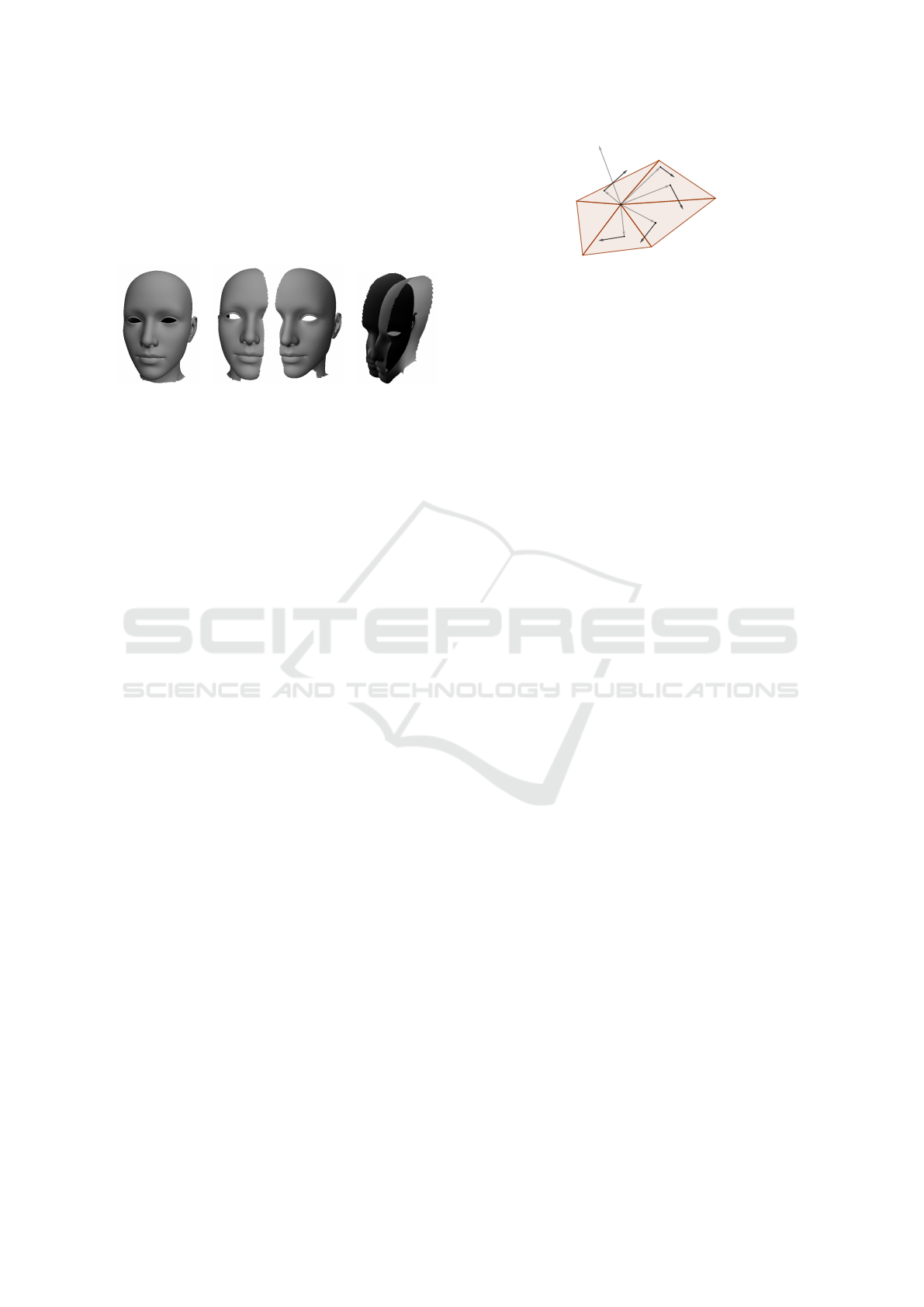
(a) (b) (c)
Figure 1: a) Original data of a human head; b) Left and right
part of the human head; c) An incorrect registration of the
two parts.
We propose two approaches to distinguishing left
and right parts in models involving symmetries. The
first approach is based on interaction of the local
shape with a strongly orientation dependent vector
field. The second approach is based on curvature es-
timation and a local coordinate system created in the
directions of the normal vectors and the extremal cur-
vatures. Both versions lead to a signed value that rep-
resents flux direction or signed volume. Based on the
sign, we can distinguish symmetric geometry parts.
3.1 Vector Field
Our first approach is based on analyzing the local
shape using a symmetry-aware vector field. Having
a surface and a vector field that goes through it, we
can calculate the flux. It describes the quantity which
passes through a surface and based on the direction of
the vector field and orientation of the surface, it has
either positive or negative sign. We can utilize this
knowledge to distinguish orientation of the local sur-
face. Symmetric parts will have opposite signs and
this can be used for the feature vector modification.
The initial derivation is based on a triangle mesh,
however, this approach can be used for point clouds
as well. First, we describe the solution based on a
triangle mesh and later explain its modification for a
point cloud.
3.1.1 Triangle Mesh
We want to calculate the feature vector at a vertex P
(equipped with the normal vector n
p
) of an input trian-
gle mesh. We define a vector field as a vector function
v(X) = (P −X)× n
p
, (1)
n
P
v(X
1
)
v(X
2
)
v(X
3
)
v(X
4
)
v(X
5
)
X
1
P
X
2
X
3
X
4
X
5
Figure 2: A local neighborhood with a few sample points X
i
and vector field values at them.
The entire setup with a few points X
i
can be seen in
Figure 2.
Our goal is to integrate the dot product of this field
with triangle normals over all neighboring triangles.
For i-th triangle, we compute the following integral:
F
i
=
Z
4
i
v(X) · n
i
d4
i
, (2)
where n
i
is the normal of the i-th triangle. Finally,
we sum these values over all triangles in a local neigh-
borhood as
F
s
=
∑
i
F
i
,
Points X in a triangle can be parameterized by
scalars r and s as:
X = A
i
+ r(B
i
− A
i
) + s(C
i
− A
i
), (3)
where A
i
, B
i
and C
i
are vertices of the triangle that
contains X, r ∈ R and s ∈ R are parameters fulfilling
the conditions r + s = 1 and r,s ≥ 0.
To calculate the integral (2), we have to change the
bounds of the integral. From the integral over the area
of triangle 4
i
, we get the integral based on the pre-
viously defined parametric function in Equation (3)
with parameters r and s:
F
i
=
1
Z
r=0
1−r
Z
s=0
v(A
i
+ r(B
i
− A
i
) + s(C
i
− A
i
)) · n
i
J
i
dsdr,
(4)
where J
i
is the Jacobian associated with the change
of the integral bounds and it is equal to J
i
= ||(B
i
−
A
i
) × (C
i
− A
i
)||. The integral from Equation 4 can be
rewritten using Equations 1 and 3 to:
F
i
= J
i
1
Z
r=0
1−r
Z
s=0
(P × n
p
· n
i
− A
i
× n
p
· n
i
−r(B
i
− A
i
) × n
p
· n
i
−s(C
i
− A
i
) × n
p
· n
i
)dsdr.
(5)
To simplify Equation 5, we use a substitution:
α
i
= (P − A
i
) × n
p
· n
i
,
β
i
= −(B
i
− A
i
) × n
p
· n
i
,
γ
i
= −(C
i
− A
i
) × n
p
· n
i
,
(6)
Symmetry-aware Registration of Human Faces
187

which leads to
F
i
= J
i
1
Z
r=0
1−r
Z
s=0
(α
i
+ β
i
r + γ
i
s)dsdr
=
1
6
J
i
(3α
i
+ β
i
+ γ
i
).
(7)
After the removal of substitution from Equation 6,
we end up with a solution
F
i
=
1
2
J
i
(P − T
i
) × n
p
· n
i
, (8)
where T
i
is a centroid of a triangle A
i
B
i
C
i
, i.e. calcu-
lated as T
i
=
1
3
(A
i
+ B
i
+C
i
).
If we compute the triangle normal t
i
as (B
i
−A
i
)×
(C
i
− A
i
), then Equation 8 can be further simplified to
F
i
=
1
2
(P−T
A
i
B
i
C
i
)×n
p
·[(B
i
−A
i
)×(C
i
−A
i
)],. (9)
3.1.2 Point Cloud Modification
Application to point clouds without connectivity is
possible if we interpret the data as a dual represen-
tation. We can think of the input points as centroids
of virtual triangles, while the actual vertices are un-
known. The idea is visualized in Figure 3: Figure 3a
shows the standard way, where points P
i
(blue color)
of the cloud are taken as vertices of triangles and cen-
troids (green color) are calculated from them, Figure
3b shows the dual interpretation, where the points P
i
(blue color) are used as centroids directly.
(a) (b)
Figure 3: a) Point cloud P
i
(blue points) as triangulation
with green centroids of triangles; b) Points P
i
of cloud (blue
points) are used as centroids of “virtual” triangles. The yel-
low points are just for illustration of one possible “virtual”
triangulation of the neighborhood.
For the point cloud modification, the overall trian-
gulation is not required. We use only points P
i
with
their normal vectors that are used as normal vectors
of the “virtual” triangles. The result can be improved
if we have available non-normalized normal vectors
that hold the information about the area of virtual tri-
angle. This is similar to the Jacobian in the triangle
mesh solution. If unit-length normal vectors are used,
the virtual triangles are considered to have equal area.
Based on this, we can directly use the Equation 9 and
get the final solution for a point cloud as:
F
i
=
1
2
(P − P
i
) × n
p
· n
i
.
The result is influenced by the size of the neigh-
borhood that is obtained by a nearest-neighbor search
within a threshold distance. A comparison of differ-
ent neighborhood sizes is shown in Figure 4, which
shows the point cloud modification. Near similar re-
sults were acquired using a triangle mesh, and there-
fore they are not included. It can be seen that with
the increasing neighborhood size, the results become
more stable. The sign of the obtained values does not
unambiguously identify the right/left side, however,
this is actually not our goal. More importantly, parts
differing only by a symmetry have a different sign and
can therefore be distinguished.
3.2 Curvature
The second proposed approach is based on curvature
estimation. It can be used for a triangle mesh or a
point cloud. There are many algorithms for a curva-
ture estimation (for a recent survey, see (V
´
a
ˇ
sa et al.,
2016)) and the selection of one depends on estimation
circumstances, such as type of input data, quality of
the input, required performance and others. Noise in
input data can lead to problems with curvature. How-
ever, due to targeting on human faces, the input data
can be partially smoothed out which limits the noise
level. The smoothing process can remove wrinkles
and other imperfections, but they are not important
for the registration.
Given the points of an input point cloud, where
we want to calculate a feature vector, for every point P
(equipped with the normal vector n) we find its neigh-
borhood. The size of the neighborhood can be se-
lected. We have used the same size as for the feature
vector calculation algorithm.
Points with the maximal (P
max
) and minimal (P
min
)
value of mean or Gaussian curvature are found within
the neighborhood. These points are used to create a
triplet of vectors: n,u = P
max
− P,v = P
min
− P. The
triplet can be used to calculate the signed volume
V
s
mean/Gauss
of a parallelepiped, see Figure 5, as:
V
s
mean/Gauss
= n · (u × v),
where the mean or Gauss index is used to distinguish
the type of extrema used for calculation of u and v.
The sign of the volume is swapped for reflected
parts, because the points P
min
and P
max
are reflected as
GRAPP 2019 - 14th International Conference on Computer Graphics Theory and Applications
188
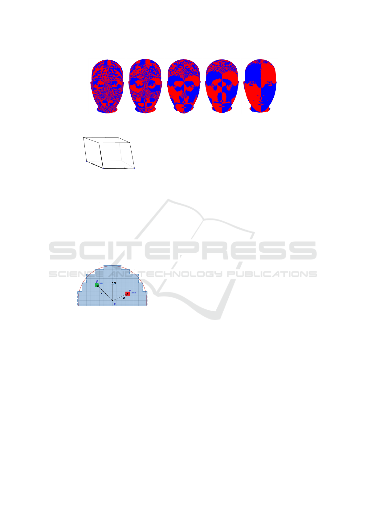
Figure 4: Comparison of neighborhoods for vector field flux. Blue color indicates negative flux, red is used for positive values.
Neighborhood sizes are taken in percents of bounding box size. From left to right: 7%, 14%, 21%, 28% and 42%.
u
vv
nn
PP
minmin
PP
PP
maxmax
Figure 5: The triplet of vectors n, u and v and indicated
signed volume of a parallelepiped.
well. However, due to the differences in the neighbor-
hoods for left and right part, the positions of extrema
are not guaranteed to be the same, which can lead to
incorrect results. A possible solution is to divide the
space into bins, eg. from the volumetric sphere cen-
tered around the point P. A simplified 2D scenario
with only upper half of circle can be seen in Figure 6.
Centroids of bins with the extremal averages of cur-
vature are used to construct the vector triplet.
Figure 6: Bins around the center point P. Two bins with the
extremal average curvatures are highlighted. Only upper,
relevant half of circle is shown.
The curvature based solution for distinguishing
left and right part behaves differently from the vec-
tor field based approach. The comparison of differ-
ent neighborhood sizes can be seen in Figure 7. For
sizes above 25%, the results are generally incorrect.
This is caused by the large smooth areas with few de-
tails where small numerical error can change the vec-
tor triplet and results in incorrectly signed area.
3.3 Symmetry-aware Feature Vector
The signed representation of the neighborhood, as
presented in subsections 3.1 and 3.2, is used to modify
the feature vector. There are many ways how to mod-
ify the feature vector. We have tested several possi-
bilities that either combine together the two represen-
tations (presented in subsections 3.1 and 3.2) or use
them separately. Attaching the value to the end (or
beginning) of the feature vector offered only a small
amount of new information and did not improve the
results. Therefore we have also considered multiply-
ing the feature vector to include the sign together with
the value. In some cases, further attaching other cal-
culated value to the end of already multiplied feature
vector further improved the results.
From all the tests, the ones that provide the best
overall quality were selected. We compute the FPFH
feature vector and use either F
s
from the Vector Field,
V
s
mean
from mean curvature or V
s
Gauss
from Gaussian
curvature for modification. In the first step, we multi-
ply FPFH by F
s
and use one of the following modifi-
cations:
1. append F
s
to the end
2. append V
s
mean
to the end
3. append F
s
, V
s
mean
and V
s
Gauss
to the end
4. append V
s
mean
and V
s
Gauss
to the end
4 EXPERIMENTS AND RESULTS
We have used one of the current state-of-the-art meth-
ods, FGR (Zhou et al., 2016), as a baseline. This
method uses FPFH feature vector to obtain the final
transformation and in some cases, it leads to an incor-
rect alignment of two parts if they contain symmetric
parts. For example, if we try to register two overlap-
ping parts of the human head, the ears are detected in
both parts with similar feature vectors, which affects
the final transformation (see again Figure 1c).
4.1 Test Data
We need an automatic evaluation of registration qual-
ity. For this purpose, the correct registration has to be
known. Therefore, instead of using scanned data, we
have recreated partially overlapping parts from com-
plete models. In our tests, We have used point clouds
as well as their triangulations.
Symmetry-aware Registration of Human Faces
189

Figure 7: Comparison of neighborhoods for signed volume. Blue color indicates negative volume, red is used for positive
values. Neighborhood sizes are taken in percents of bounding box size. From left to right: 7%, 14%, 21%, 28% and 42%.
To create overlapping parts from a complete
model and simulate a scanning device, we use the fol-
lowing steps.
• The plane of symmetry is found.
• The plane is randomly rotated around the coordi-
nate system axes in the interval < −30°,30° >.
Larger rotation will cause too large overlaps
which lead to easy registration.
• The plane is shifted in positive or negative direc-
tion of its normal vector. Shift distance depends
on the model size and the size of the overlap we
want to achieve.
• Vertices in one half-space of the plane are dis-
carded
However, in this scenario, data can be matched 1:1 -
e.g. there are points in both halves that can be exactly
matched. To overcome this, we have added Gaussian
noise to the data. In addition, for triangle meshes,
Loop (Loop, 1987) subdivision scheme followed by a
mesh simplification was used.
4.2 Comparison Metric
To compare the registration results, we have used a
metric based on (Pottmann et al., 2006). From the
two parts that are used for the registration, one (called
model P) is at a fixed position and the other (called
model Q) is transformed with a random translation
and rotation. Inverse of this transformation will put
the model to a position Q
1
in which it is correctly reg-
istered with model P.
We have obtained the registration matrix from the
registration algorithm and transformed the model Q
with this matrix which led to the position Q
2
. For a
perfect registration, Q
1
and Q
2
are the same. To mea-
sure the deviation from a perfect registration, we com-
pute distances between the corresponding vertices of
Q
1
and Q
2
. The sum of distances is divided by the
number of vertices and normalized by the data radius,
making the value scale independent, although not nec-
essarily in the < 0,1 > interval.
Based on our observations, the resulting values
can be interpreted as follows: Values under 0.1 can
be considered a correct registration result. Values be-
tween 0.1 and 0.6 are registered very roughly, but the
overall shape can be recognized. Values above 0.6
indicate incorrect registration and the result is on par
with a random matrix.
4.3 Tests
The core of the tests is based on the FPFH descriptor.
We have used several radii that are based on the aver-
age number of points that fall within. We have started
with 10 points and ended with a neighborhood of the
size 160 points, using a step of 10 points. From the
number of points, we have calculated the average ra-
dius size of the geometry and this radius was used for
FPFH. The radius was different for each tested model,
depending on the model scale and sampling density.
In our experiments, we have used the same ra-
dius for both FPFH calculation and for the calcula-
tion of neighborhoods for the proposed methods. We
have tested different sizes of neighborhoods as well.
However, for smaller neighborhoods (< 10) the re-
sults were often similar to a flat surface. There were
certain precision improvements with neighborhoods
of larger size (> 160), but the computation times were
longer. As a trade-off between quality and speed, we
have selected using neighborhoods of the same size.
We have created an automated test scenario, where
the input model is randomly divided into two overlap-
ping parts (see subsection 4.1). For every split, we
have computed metrics for every variation of the fea-
ture vector modification proposed in subsection 3.3.
The basic solution taken from FGR was able to cor-
rectly register only about 40% of our input test cases,
while the rest was registered incorrectly (with metric
values being above 0.1).
We have conducted several thousand tests with
different models of human heads and faces. For the
tests, we have used a triangle mesh and a point cloud
representation of the input model. The overall results
were roughly the same for both approaches and corre-
spond with averaged results. These overall averaged
GRAPP 2019 - 14th International Conference on Computer Graphics Theory and Applications
190
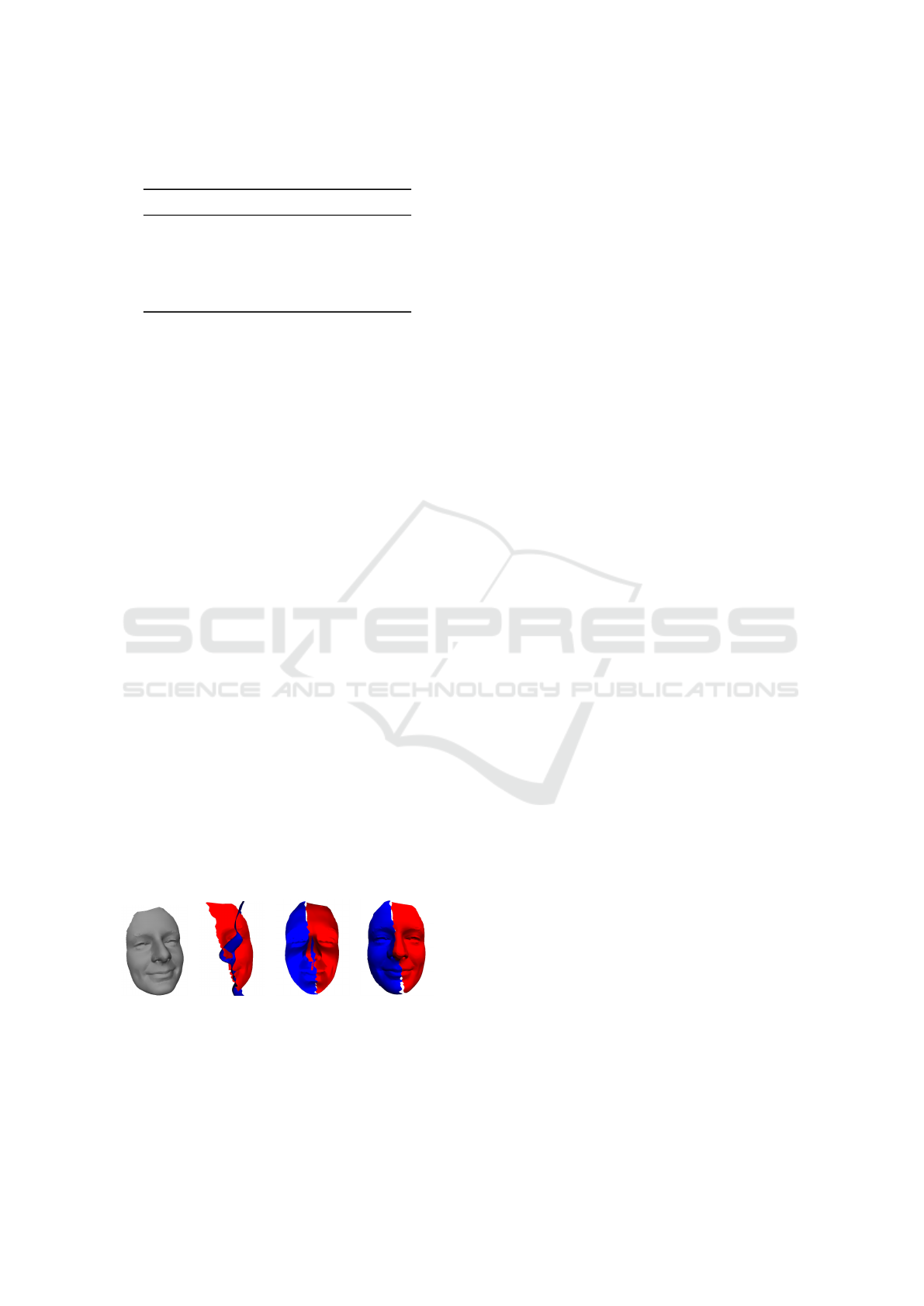
Table 1: Comparison of successfully registered input cases
based on different points count in the neighborhood.
Method Size 10 Size 60 Size 150
- 41% 43% 34%
1 44% 42% 28%
2 48% 45% 33%
3 51% 50% 31%
4 55% 49% 36%
results are presented in Table 1. The method number
in the first column of the table corresponds with the
feature vector modification method number from sub-
section 3.3. The symbol ”− ” marks the original FGR
method without any modification. The table shows
the percentage of correct registrations for three differ-
ent neighborhood sizes (10, 60 and 150). Note that
the globally low success rate in general is caused by
an automated data creation, which often leaves only a
small overlap.
We have observed that with the increasing neigh-
borhood size, the results were improving only to a cer-
tain threshold. The quality of the registration began to
decrease for a neighborhood calculated from around
60 points, probably because the descriptor was con-
structed from a too large area. For a human head,
it often means that a large part of the descriptor is
based on smooth surfaces (cheeks, forehead or chin).
In these cases, the basic FGR algorithm offers better
results.
The visual comparison of results can be seen in
Figure 8. The original data (Figure 8a) differs from
the best registration result (Figure 8d) because of the
data modification described in Subsection 4.1. The
difference between Figure 8c and Figure 8d is mainly
in the nose area. The two parts in Figure 8c are reg-
istered very roughly and there are many intersections
of the two parts along their overlap. In Figure 8d the
registration is correct with a smooth transition from
one part to another. The missing parts are caused by
the automated data creation.
(a) (b) (c) (d)
Figure 8: Visual comparison of results; a) Original data;
b) FGR only, error = 1.578; c) The proposed registration,
error = 0.192; d) The proposed registration, error = 0.074.
4.4 Limitations
The proposed algorithm has certain limitations. Some
of them are globally related to the registration itself.
If the overlap of two parts is too small, the resulting
registration is often incorrect. The same goes for too
much noise in the data.
The main problem of the proposed solution is se-
lecting optimal feature vector modification. Depend-
ing on the data, one choice may be considerably bet-
ter than others. This is currently solved manually,
when the user has to check if the registration is cor-
rect. In future research, we would like to focus on this
part and create an automated system that can distin-
guish incorrect registration automatically and eventu-
ally choose another feature vector. We have already
experimented with solutions based on projections of
geometry to 2D plane and comparison of projected
depth values, but the results are currently not reliable.
Our current solution is only suitable for a limited
set of data - scans of human heads. We have also
tested general models with symmetries, however, the
quality of registration was not globally improved with
our algorithm.
5 CONCLUSIONS
An improvement of the registration for scanned data
of human head was proposed. The solution can be
implemented into existing registration algorithms as
an extension of the currently existing feature vector.
We have shown that augmenting a feature vector by
our symmetry aware measures leads to a considerable
improvement in registration success rate.
Currently, we do not have a single feature vector
augmentation strategy that works best in all cases. If
the best possible result is required, user interaction is
necessary. The user must decide whether or not the
registration is correct. This is far from ideal, although
such solution is still faster than manually finding the
transformation. Moreover, the decisions of correct-
ness can be made by a layman, while a manual reg-
istration requires certain experience. In our future re-
search, we would like to remove this limitation by us-
ing an automatic detection of registration correctness.
As a part of our future work, we would like to ex-
tend our proposed algorithm to general models. The
current solution can be naturally applied to any mod-
els, but the improvement of registration unfortunately
is not significant in the general case.
Symmetry-aware Registration of Human Faces
191

ACKNOWLEDGEMENT
This publication was supported by the project
LO1506 of the Czech Ministry of Education, Youth
and Sports under the program NPU I.
REFERENCES
Bay, H., Ess, A., Tuytelaars, T., and Gool, L. V. (2008).
Speeded-up robust features (surf). Computer Vision
and Image Understing, 110(3):346–359.
Drost, B., Ulrich, M., Navab, N., and Ilic, S. (2010). Model
globally, match locally: Efficient and robust 3d object
recognition. In 2010 IEEE Computer Society Con-
ference on Computer Vision and Pattern Recognition,
pages 998–1005.
Elbaz, G., Avraham, T., and Fischer, A. (2017). 3d point
cloud registration for localization using a deep neu-
ral network auto-encoder. In 2017 IEEE Conference
on Computer Vision and Pattern Recognition (CVPR),
pages 2472–2481.
Foulds, H. and Drevin, G. R. (2011). Three-dimensional
shape descriptors and matching procedures. In WSCG
’2011: The 19th International Conference in Cen-
tral Europe on Computer Graphics, Visualization and
Computer Vision, p. 1-8., pages 1–8.
Gelfand, N., Mitra, N. J., Guibas, L. J., and Pottmann, H.
(2005). Robust global registration. In Proceedings of
the Third Eurographics Symposium on Geometry Pro-
cessing, SGP ’05, Aire-la-Ville, Switzerland, Switzer-
land. Eurographics Association.
Guo, Y., Bennamoun, M., Sohel, F., Lu, M., Wan, J., and
Kwok, N. M. (2016). A comprehensive performance
evaluation of 3d local feature descriptors. Interna-
tional Journal of Computer Vision, 116(1):66–89.
Holz, D., Ichim, A. E., Tombari, F., Rusu, R. B., and
Behnke, S. (2015). Registration with the point cloud
library: A modular framework for aligning in 3-d.
IEEE Robotics Automation Magazine, 22(4):110–124.
Jiaqi, Y., Zhiguo, C., and Qian, Z. (2016). A fast and robust
local descriptor for 3d point cloud registration. Infor-
mation Sciences, 346-347:163 – 179.
Johnson, A. E. and Hebert, M. (1999). Using spin images
for efficient object recognition in cluttered 3d scenes.
IEEE Transactions on Pattern Analysis and Machine
Intelligence, 21(5):433–449.
Knopp, J., Prasad, M., Willems, G., Timofte, R., and Gool,
L. V. (2010). Hough transform and 3d surf for robust
three dimensional classification. In Proceedings of the
11th European Conference on Computer Vision: Part
VI, ECCV’10, pages 589–602. Springer Berlin Hei-
delberg.
Lin, B., Wang, F., Sun, Y., Qu, W., Chen, Z., and Zhang,
S. (2017). Boundary points based scale invariant 3d
point feature. Journal of Visual Communication and
Image Representation, 48:136 – 148.
Liu, H., Yan, J., and Zhang, D. (2006). A neural net-
work strategy for 3d surface registration. In Compu-
tational Science and Its Applications - ICCSA 2006,
pages 528–536. Springer Berlin Heidelberg.
Loop, C. (1987). Smooth Subdivision Surfaces Based on
Triangles. PhD thesis, Department of Mathematics,
The University of Utah, Masters Thesis.
Lowe, D. G. (2004). Distinctive image features from scale-
invariant keypoints. International Journal of Com-
puter Vision, 60(2):91–110.
Maximo, A., Patro, R., Varshney, A., and Farias, R. (2011).
A robust and rotationally invariant local surface de-
scriptor with applications to non-local mesh process-
ing. Graphical Models, 73(5):231 – 242.
Pottmann, H., Huang, Q. X., Yang, Y. L., and Hu, S. M.
(2006). Geometry and convergence analysis of al-
gorithms for registration of 3d shapes. International
Journal of Computer Vision, 67(3):277–296.
Pottmann, H., Wallner, J., Yang, Y. L., Lai, Y., and Hu,
S. M. (2007). Principal curvatures from the integral
invariant viewpoint. Computer Aided Geometric De-
sign, 24(8 - 9):428 – 442.
Rusu, R. B., Blodow, N., and Beetz, M. (2009). Fast
point feature histograms (fpfh) for 3d registration. In
Robotics and Automation, 2009. ICRA ’09. IEEE In-
ternational Conference on Robotics and Automation,
pages 3212–3217.
Tombari, F., Salti, S., and Stefano, L. D. (2010). Unique
signatures of histograms for local surface descrip-
tion. In Proceedings of the 11th European Conference
on Computer Vision Conference on Computer Vision:
Part III, ECCV’10, pages 356–369. Springer Berlin
Heidelberg.
V
´
a
ˇ
sa, L., Van
ˇ
e
ˇ
cek, P., Prantl, M., Skorkovsk
´
a, V., Mart
´
ınek,
P., and Kolingerov
´
a, I. (2016). Mesh statistics for ro-
bust curvature estimation. Computer Graphics Forum,
35(5):271–280.
Zhou, Q. Y., Park, J., and Koltun, V. (2016). Fast global
registration. In Computer Vision – ECCV 2016, pages
766–782, Cham. Springer International Publishing.
GRAPP 2019 - 14th International Conference on Computer Graphics Theory and Applications
192
