
Study on the Influence of Tool Rotating Speed on the Weld Joint
Strength of Friction Stir Welding Method
Sarjito Joko Sisworo and Ahmad Fauzan Zakki
Department of Naval Architecture, Diponegoro University, Semrang, Indonesia
ahmadfauzanzakki@lecturer.undip.ac.id
Keywords: Aluminum 6061, Friction Stir Welding, RPM Speed, Tensile, Impact, Micrographic Test.
Abstract: Aluminum 6061 is a lightweight metal and has a corrosion resistance and good conductivity. In the marine
industry, aluminum 6061 is widely used for ship construction. Friction Stir Welding (FSW) uses the
principle of utilizing friction from a rotating work piece with another stationary work piece so that it is able
to melt the stationary work piece and finally connect it together. The focused of this study is to determine
the impact strength, tensile strength and micrographic structure of the butt joint of FSW Welding. The feed
rate is determined as 10 mm / min with the variations of rpm speed is defined as 1640 rpm, 2620 rpm, and
3820 rpm. Tensile strength, impact strength and micrographic evaluation will be discussed to assess the
effect of rotational speed on the strength of the welded joint produced by Friction Stir Welding.
1 INTRODUCTION
In the era of modern technology, humans are
required to create an effective and efficient progress
and development that can give benefits to the society
in all of fields. One of the fields is the field of
marine and shipbuilding industry. Technological
developments in the shipbuilding industry are the
use of various types of materials such as steel,
aluminum, fiberglass, etc. All of the types of
materials have advantages and disadvantages. One
type of material that has good strength against
corrosion is aluminum.
Aluminum is a metal that has relatively low
strength and soft. Aluminum is a lightweight metal
and has good corrosion resistance, good electrical
conductivity and other properties. Generally
aluminum is mixed with other metals to form
aluminum alloys. Aluminum 6061 is a kind of
aluminum alloy between magnesium and silicon that
has good mechanical properties without reducing
electrical conductivity. In the marine industry,
aluminum is widely used for construction in piping
and tank sections such as fresh water tanks or fuel
tanks. Aluminum is a metal that has mechanical
properties that are resistant to corrosion and
relatively good electrical conductivity. This metal is
widely used not only for household appliances, but
also for aircraft, automotive, marine and building
construction materials, (Surdia et. al., 1999).
FSW (Friction Stir Welding) is a welding
method that was discovered and developed by
Wayne Thomas for aluminum and aluminum alloy
work pieces in 1991 at TWI (The Welding Institute)
in the United States (Nandan et. al., 2009). The
working principle of FSW is to utilize the friction of
a rotating work piece with another stationary work
piece so that it is able to melt the stationary work
piece and finally connect it together. The welding
process with FSW occurs in solid conditions (Solid
State Joining). The welding process with FSW
occurs at the temperature of the solvus, so there is no
decrease in strength due to over aging and the
dissolution of coherent deposits. Since the welding
temperature is not too high, the residual stresses and
the distortion that are formed due to heat are also
low (ASM, 2007). The mechanical characteristics of
the weld joint in the FSW are determined by the
parameters: welding speed, tool rotation, and tool
pressure (Jayamaran et. al., 2009).
The application of FSW technique to support the
manufacture of marine structures and shipbuilding
also can be found in (Maggiolino, 2008; Feistauer,
2014; Farajkhah, 2016; Singh, 2019; Ramesh, 2020).
Previous studies have conducted a study on the
effect of rotating tools on micro structures and
mechanical properties of friction stir welding
60
Sisworo, S. and Zakki, A.
Study on the Influence of Tool Rotating Speed on the Weld Joint Strength of Friction Stir Welding Method.
DOI: 10.5220/0010055200600066
In Proceedings of the 7th International Seminar on Ocean and Coastal Engineering, Environmental and Natural Disaster Management (ISOCEEN 2019), pages 60-66
ISBN: 978-989-758-516-6
Copyright
c
2021 by SCITEPRESS – Science and Technology Publications, Lda. All rights reserved

connections on aluminum alloy 6061 (Wartono et.
al., 2015) where in that study using tools rotation
speed: 540 rpm, 910 rpm, and 1500 rpm. Tensile test
results showed that the average ultimate strength for
welding using 540 rpm tool speed was 139 MPa, for
910 rpm tool speed was 157 MPa and at 1500 rpm
tool speed was 155 MPa. With these results it can be
seen that the highest ultimate strength is to use the
910 rpm tool rotation. Furthermore, in case of the
impact strength behaviour, the weld joint impact
strength at 540 rpm has magnitude of 0.594 (J/mm
2
),
for a speed of 910 rpm it has an impact strength of
0.624 (J/mm
2
), and at a speed of 1500 rpm has an
impact strength of 0.573 (J/mm
2
).
In this study a similar study was made, however
the rotational speed was significantly increased by:
1640 rpm, 2620 rpm, and 3820 rpm. The
experimental studies was conducted to assess the
strength of the connection consist of tensile test,
impact test and micrographic test.
2 PREPARATION AND TESTING
METHOD OF THE WELD
JOINT
The Aluminum 6061 was produced by the local steel
industry that was used in the ship production process
with the thickness 10 mm. The material properties of
the Aluminum 6061 can be seen in the Table 1.
Table 1: Mechanical properties of Aluminum 6061.
Aluminum 6061
Poisson’s Ratio 0,33
Modulus Of Elasticity 68,9 GPa
Density 2700 kg/m
3
Yield stress 276 MPa
Fatigue Strength 633 MPa
Failure Strain 0,39
Tensile Strength 324 MPa
The specimens are made for the purposes of
tensile testing, impact testing and micrographic
testing. In making specimens for test experiments
not used the standard ASTM E8 / E8M-09.
Illustration of dimensions and shape of tensile test
specimens can be seen in Fig. 1. In impact test
experiments, specimen preparation is carried out
using the ASTM E23 standard. Illustration of
dimensions and shape of the impact test specimens
can be seen in Fig 2. The existing welded joints on
the specimens were made using the friction stir
welding method with the rotating pin tool with
variations in the pin tool speed of 1640 rpm, 2620
rpm, and 3820 rpm. Illustration of pin tool
dimensions can be seen in Fig. 3. The numbers of
specimens in the tensile test and impact test are 3
specimens, while for the micrographic test are 1
specimen.
Gage length (G) : 50.0 mm
Length of reduced section (A) : 57 mm
Width (W) : 12.5 mm
Thickness (T) : 10 mm
Radius of fillet (R) : 12.5 mm
Overall length (L) : 200 mm
Width of grip section (C) : 20 mm
Length of grip section (B) : 50 mm
Figure 1: Tensile test specimen (ASTM E8/E8M-09).
Overall length (L) : 55 mm
Width (W) : 10 mm
Thickness (T) : 10 mm
Notched Charpy : 45°
Figure 2: Impact test specimen (ASTM E23).
The weld joint specimens were prepared by
friction stir welding method. The universal milling
machine was used to create the weld joint.
Rotational speed of universal milling machine can
be arranged with the maximum rotational speed of
4000 rpm. In this study the rotational speed was
determined on 1640 rpm, 2620 rpm, and 3820 rpm.
The universal milling machine has been equipped
with an automatic moving table. Therefore the
friction stir welding process can be accomplished
with the steady travel speed. The travel speed of the
rotating tool of the welding process was determined
as 30 mm/min. The rotating pin tool has the main
function to generate the heat and to mix the work
piece material. Therefore the material of the rotating
tool should have a higher melting point compare
with the weld material. The K-110 KNL EXTRA
steel was selected as the material of the rotating tool.
Study on the Influence of Tool Rotating Speed on the Weld Joint Strength of Friction Stir Welding Method
61
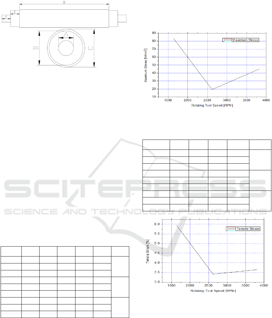
Material of Pin : KNL 110 Extra
Hardness : 61 HRC
Diameter of Pin (A) : 8 mm
Diameter of Probe (B) : 18 mm
Diameter of Tools (C) : 20 mm
Length of Tools (D) : 70 mm
Length of Probe (E) : 10 mm
Length of Pin (F) : 9.5 mm
Figure 3: Illustration of the rotating pin tool design.
3 RESULTS AND DISCUSSIONS
3.1 Tensile Strength Test Results
From the tests that have been done, the results
obtained in Table 2, tensile testing show that the
value of the maximum tensile strength resulting
from the FSW (Friction Stir Welding) welding
carried out in this research is 88.13 MPa at a speed
of 1640 rpm (specimen 2), and the result of the
smallest tensile strength is 16.80 MPa at a speed of
2620 rpm (specimen 3).
Table 2: Tensile stress of Aluminum 6061.
Specimen
Thick.
(mm)
Width
(mm)
Area
(mm
2
)
P Max
(N)
σ Max
(MPa)
σ aver.
(MPa)
X1 10.09 12.76 128.75 10630 82.56
83.34
X2 10.08 12.72 128.22 11300 88.13
X3 10.10 12.93 130.59 10360 79.33
Y1 10.55 12.57 132.61 2750 20.74
19.27
Y2 10.58 12.30 130.13 2640 20.29
Y3 10.35 12.94 133.93 2250 16.80
Z1 10.26 12.82 131.53 7440 56.56
45.02
Z2 10.36 12.97 134.37 4970 36.99
Z3 10.38 13.02 135.15 5610 41.51
The average magnitude of the tensile strength of
the aluminum 6061 weld joint using FSW (Friction
Stir Welding) welding with variations in the tool
rotation speed carried out in this research was 83.34
MPa at 1640 rpm, 45.02 MPa at 3820 rpm, and
19.27 MPa at 2620 rpm. Before the tensile test is
carried out, a visual inspection of the welding
surface is carried out first, and the speed of 2620
rpm has the worst weld results. There are worm
holes after welding is the main reason that reduces
the tensile strength test results on the specimen with
a speed of 2620 rpm.
Figure 4: Tensile stress of Aluminum 6061 at the defined
rotating tool speed.
Table 3: Tensile strain of Aluminum 6061.
Specimen
L0
(mm)
L1
(mm)
ΔL
(mm)
Strain ε
(%)
ε aver.
(MPa)
X1 50 52.11 2.11 4.21
5.93
X2 50 53.86 3.86 7.71
X3 50 52.93 2.93 5.87
Y1 50 51.92 1.92 3.84
3.41
Y2 50 51.66 1.66 3.31
Y3 50 51.53 1.53 3.07
Z1 50 52.03 2.03 4.06
3.65
Z2 50 51.92 1.92 3.83
Z3 50 51.53 1.53 3.06
Figure 5: Tensile strain of Aluminum 6061 at the defined
rotating tool speed.
Based on the conducted test results of tests in
this study, the maximum tensile strain value
resulting from friction stir welding joints which was
occurred on aluminum 6061 is 7.71% at a speed of
1640 rpm specimen 2, and the smallest tensile strain
yield is 3 .07% at a speed of 2620 rpm specimen 3.
The average tensile strain value from highest to
lowest resulting from the aluminum 6061 weld joints
using FSW (Friction Stir Welding) welding with
ISOCEEN 2019 - The 7th International Seminar on Ocean and Coastal Engineering, Environmental and Natural Disaster Management
62

variations in the tool rotation speed carried out in
this research was 5.93% at 1640 rpm, 3.65% at 3820
rpm, and 3.41% at 2620 rpm.
Table 4: Modulus of elasticity of Aluminum 6061.
Specimen
σ Max
(MPa)
Strain ε
(%)
E
(GPa)
E aver.
(GPa)
X1 82.56 4.21 19.61
14.85
X2 88.13 7.71 11.42
X3 79.33 5.87 13.52
Y1 20.74 3.84 5.40
5.67
Y2 20.29 3.31 6.13
Y3 16.80 3.07 5.47
Z1 56.56 4.06 13.93
12.38
Z2 36.99 3.83 9.65
Z3 41.51 3.06 13.57
Figure 6: Modulus of elasticity of Aluminum 6061 at the
defined rotating tool speed.
From the diagram of the test results that have
been carried out, the highest elastic modulus value at
the aluminium 6061 weld joint using FSW (Friction
Stir Welding) welding is 19.61 GPa at a speed of
1640 rpm specimen 1. While the lowest elastic
modulus value of the specimen of aluminum 6061
weld joint using FSW (Friction Stir Welding) at a
speed of 2620 rpm specimen 1 has shown a modulus
of elasticity of 5.4 GPa. From the highest to lowest,
the average modulus of elasticity of the aluminum
6061 welding connection using FSW (Friction Stir
Welding) welding is 14.85 GPa at 1640 rpm; 13.81
Gpa at a speed of 3820 rpm; and 5.67 Gpa at a speed
of 2620 rpm.
3.2 Impact Strength Test Results
From the diagram of the results of the tests that have
been done, the impact strength on the aluminum
6061 weld joint using FSW (Friction Stir Welding)
welding is 0.27 J/mm
2
at 3820 rpm of specimen 1.
While the lowest impact strength on the aluminum
6061 weld joint using FSW welding (Friction Stir
Welding) is produced at a rotating speed of 2620
rpm specimen 2 with an elastic modulus value of
0.10 J/mm
2
. The highest to lowest average impact
value generated at the aluminum 6061 weld joint
using FSW (Friction Stir Welding) welding is 0.23
J/mm
2
at 1640 rpm; 0.20 J/mm
2
at a rotating speed
of 3820 rpm; and 0.13 J/mm
2
at a rotating speed of
2620 rpm.
Table 5: Impact strength of Aluminum 6061.
Specimen
Width
(mm)
Height
(mm)
Absorbed
Energy
(J)
Impact
Strength
(J/mm
2
)
Impact
Strgh. aver.
(J/mm
2
)
X1 10.16 8.88 22.18 0.25
0.23
X2 10.28 9.00 17.08 0.18
X3 10.20 8.88 23.95 0.26
Y1 10.21 9.29 10.78 0.11
0.13
Y2 10.16 8.77 8.65 0.10
Y3 10.16 8.66 15.45 0.18
Z1 10.23 9.24 25.75 0.27
0.20
Z2 10.26 9.31 16.18 0.17
Z3 10.32 8.67 14.45 0.16
Figure 7: Impact strength of Aluminum 6061 at the
defined rotating tool speed.
3.3 Micrographics Test Results
The specimens used for micrographic testing are
impact specimens with a size of 55 mm × 10 mm ×
10 mm as many as 3 specimens of FSW weld joint.
The shape of the microstructure at the aluminum
6061 weld joint can be seen through the surface
treatment which is carried out on the test specimen
so that the micro structure of the aluminum weld
joint can be clearly observed using a microscope.
Firstly, the specimens are smoothly grinded using 4
sequences of sandpaper layers, namely sandpaper
numbers 100, 200, 400, 600 and 1000. After being
smooth, then the specimen is smeared with the
autosol until glossy. After that, the surface of the
specimen that has been smeared with autosol is then
given a 50% NaOH etching solution so that when
viewed using a microscope, the microstructure of the
aluminium 6061 welded joint can be clearly seen.
Furthermore, micrographic testing is performed to
Study on the Influence of Tool Rotating Speed on the Weld Joint Strength of Friction Stir Welding Method
63
see the microstructure shape of the aluminum 6061
weld joint using a microscope with a magnification
of 200 times.
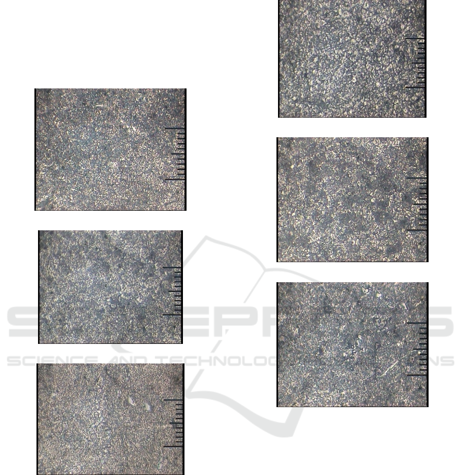
From micrographic testing on aluminum 6061
welding (Base Metal, HAZ, and Weld Joint) using
FSW (Friction Stir Welding) welding, the following
results were obtained, see Fig. 8 − Fig. 10:
[a] Weld Joint Region
[b] HAZ Region
[c] Base Metal Region
Figure 8: Microstructure of the aluminium 6061 weld joint
at 1640 RPM.
From the micrographics test, the results of the
aluminium 6061 weld joint using FSW (Friction Stir
Welding) welding with variations in the rotational
speed of the tool was presented in the form of
particle size and shape at the regions of the HAZ
(Heat Affected Zone), the base metal and the weld
joint. In the base metal area has a small grain size,
because the base metal region is not affected by the
effects of heat due to welding. Otherwise, in the
[a] Weld Joint Region
[b] HAZ Region
[c] Base Metal Region
Figure 9: Microstructure of the aluminium 6061 weld joint
at 2620 RPM.
HAZ region, particle granules change in the shape
and grain size larger and coarser, and the density of
particles is more tenuous when compared to the base
metal region. This is because the HAZ is only
affected by heat caused by friction when welding
process occurred.
In the area of the steering zone changes in the
shape and particle size looks rough and larger than
the particle size in the HAZ and base metal. This is
caused by the temperature and rotational movement
of the tool when welding around the stir zone. In
Fig. 8[a], Fig. 9[a] and Fig. 10[a], the weld joint
region (stir zone) will have soft granules which are
caused by recrystallization.
ISOCEEN 2019 - The 7th International Seminar on Ocean and Coastal Engineering, Environmental and Natural Disaster Management
64

[a] Weld Joint Region
[b] HAZ Region
[c] Base Metal Region
Figure 10: Microstructure of the aluminium 6061 weld
joint at 3820 RPM.
Based on the results of micrographic testing, the
higher of the rotation speed, the grain size of the
particles produced is greater, it is caused by several
factors such as heat input, welding rate and magnitude
of cooling rate. Therefore the weld joint at a speed of
1640 rpm has a good density level compared to the
weld joint that is produced on the speed of 2620, and
3820 rpm. It can be seen on the results of the
micrographics photo in the HAZ region.
4 CONCLUSIONS
The tensile test results of the weld joint with FSW
(Friction Stir Welding) welding have an average
stress of 83.34 MPa and an average strain of 5.93%
at a rotational speed of 1640 rpm. At a rotation
speed of 2620 rpm it has an average stress of 19.27
MPa and an average strain of 3.41%. An average
stress of 45.02 MPa and an average strain of 3.65%
are held at the 3820 rpm. Prior to the tensile test,
visual inspection of the welding surface should be
carried out, and the speed of 2620 rpm has the worst
weld results. There are hot cracks and worm holes
after welding is the main reason that reduces the
tensile strength test results on the specimen with a
speed of 2620 rpm.
The impact test results on the results of welding
joints with FSW welding have the average impact
strength of 0.23 J at the rotating speed of 1640 rpm.
The average impact of 0.13 J was appeared at 2620
rpm rotation speed, and at the rotating speed of 3820
rpm of the tool has the average impact strength of
0.20 J.
Micrographic structure test results which is
obtained in the HAZ region, and weld joint (nugget
zone) at each tool rotation has a grain size larger
than the base metal, it is caused by the influence of
the tool rotation speed. The larger of the tool
rotation, the greater the grain size produced in the
welding results.
ACKNOWLEDGEMENTS
This work was funded by the Engineering Faculty,
Diponegoro University, through the Strategic
Research Scheme-2019 (Penelitian Strategis-2019).
REFERENCES
ASM, 2007. Friction Stir Welding and Processing. ASM
International Material Park, Ohio.
Farajkhah, V., Liu, Y., 2016. Effect of fabrication methods
on the ultimate strength of aluminium hull girders,
Ocean Engineering, vol. 114, pp. 269-279.
Feistauer, E.E., Bergmann, L.A., Barreto, L.S., Dos
Santos, J.F., 2014. Mechanical behaviour of dissimilar
friction stir welded tailor welded blanks in Al–Mg
alloys for Marine applications, Materials and Design,
vol. 59, pp. 323-332.
Jayamaran, M. Sivasubramanian, R., Balasubramanian,
V., Lakshminarayanan, A.K., 2009. Optimization of
process parameters for friction stir welding of cast
aluminium alloy A319 by Taguchi method. Journal of
Scientific & Industrial Research, vol. 68, pp. 36-43.
Maggiolino, S., Schmid, C., 2008. Corrosion resistance in
FSW and in MIG welding techniques of AA6XXX,
Journal of Material Processing Technology, vol. 197,
pp. 237-240.
Study on the Influence of Tool Rotating Speed on the Weld Joint Strength of Friction Stir Welding Method
65

Nandan, R., Debroy, T., 2008. Recent advances in
friction-stir welding – Process, weldment structure and
properties, Progress in Materials Science 53, pp. 980–
1023.
Ramesh, N.R., Kumar, V.S.S., 2020, Experimental
erosion-corrosion analysis of friction stir welding of
AA 5083 and AA 6061 for sub-sea applications,
Applied Ocean Research, vol. 98, 102121.
Singh, P., Biswas, P., Kore, S.D., 2019. Influence of
Traverse Speed in Self-Reacting FSW of AA6061-T6,
Journal of Ship Production and Design, vol. 35, no. 1,
pp. 69-79.
Surdia, T., Shinroku, 1999. Knowledge of Material
Engineering. Jakarta: Pradnya Paramita.
Wartono, W., Kuntara, H., 2015. Study on the effect of
rotating tools on micro structures and mechanical
properties of friction stir welding connections on
aluminum alloy 6061, Proceeding of ReTII national
seminar, pp. 1039–1044.
ISOCEEN 2019 - The 7th International Seminar on Ocean and Coastal Engineering, Environmental and Natural Disaster Management
66
