
Numerical Investigation of Thermal Storage System in a Single-Tan
k
for CSP Plants
Mohamed Hajjaj
1
, Aumeur El Amrani
2
and Abella Bouaaddi
1
1
LGEMS,Dept.of Physics, National School of Applied Sciences, Ibn Zohr University Agadir, Morocco
2
EPSMS,Dept.of Physics, FST B.P.509, Boutalamine, Errachidia, My ismail University, Morocco
Keywords: Concentrating solar power, Thermal energy storage, Thermocline, Single- tank, Method of characteristics.
Abstract: To avoid the intermittency behavior in solar energy system due to unforeseen weather conditions and to
improve the energy availability, thermal energy storage (TES) system remains inevitable. Thus, a single
tank packed bed thermocline based TES system can provide an effective solution. This paper reports a
study on the thermal energy storage in a thermocline tank having a solid filler material. A comprehensive
one-dimensional non-thermal equilibrium model is considered and is solved using method of characteristics
for the energy storage investigation in a single tank packed bed thermocline storage system. In this present
study, the governing equations are approached from a new numerical method perspective. The governing
equations are reduced to dimensionless forms, which allow a universal application of the solution. The
dimensionless equations, which are as a system of hyperbolic type, are solved numerically by the method of
characteristics.
1 INTRODUCTION
Many studies are underway on renewable energy
related to the issue of fossil fuel depletion and the
request of new energy sources. In particular, studies
using solar energy have been actively conducted
over the last few decades. In addition, CSP
technologies generates electricity by transferring
heat from solar receivers to a heat transfer fluid and
then to steam, which is expanded through a turbine.
Moreover, CSP not only supports the base load, but
it also saves extra energy during the daytime. This
energy can then be used at night, when solar power
is lacking. Thus, thermal energy storage (TES) is a
core technology that increases the total system
efficiency by increasing the plant operation time. It
is essential to develop a thermal storage tank with
efficient thermal energy storage and energy
discharge.
The important issue related to TES for CSP
plants is high-temperature storage. Generally, high-
temperature thermal storage is required to produce
high-temperature steam, leading to enhanced power
efficiency. However, the maximum temperature of a
solar receiver at current CSP plants (i.e. Crescent
dunes, Gemasolar) using molten salt is
approximately 565°C (1050F), which may be related
to the decomposition of the molten salt. In addition,
price competitiveness is important in TES of CSP
because TES is known to be responsible for
approximately 20% of the total price. Therefore, the
development of cost competitive high-temperature
TES approaches is crucial for the commercialization
of CSP technology.
For high-temperature storage, molten salt is
generally used as the heat transfer fluid (HTF)
because the decomposition temperature of molten
salt (~550°C) remains higher than that of other types
of HTF (i.e. oil). However, the relatively high
melting temperature and material competitiveness
are still concerns. ‘Hitec’ and ‘Solar salt’ are widely
used as commercial HTFs [1].
In order to reduce the cost of TES, thermocline
TES, which enables thermal storage and discharge in
one tank, has been investigated. Thermocline TES
refers to a means of storing high- and low-
temperature fluids in a single tank by means of
thermal stratification. The core technology is to
prevent the mixing of the high and low-temperature
fluids during the charge and discharge operations.
The piping design and insulation technology
associated with the thermal storage tank are the key
technologies. Thermocline TES has not been put
El Amrani, A. and Bouaaddi, A.
Numerical Investigation of Thermal Storage System in a Single-Tank for CSP Plants.
DOI: 10.5220/0009775502910296
In Proceedings of the 1st International Conference of Computer Science and Renewable Energies (ICCSRE 2018), pages 291-296
ISBN: 978-989-758-431-2
Copyright
c
2020 by SCITEPRESS – Science and Technology Publications, Lda. All rights reserved
291
into practical use, but it is technically feasible in
order to lower the TES cost.
In this paper, we will discuss some modelling
approaches for single-tank thermocline storage
having solid filler material for CSP plants. Several
studies involving numerical analyses on solar-
assisted thermal storage systems [2,3] and
experimental studies of thermocline water storage
systems [4,5] have been reported. However, there is
limited information available on the thermocline
TES using molten salt as a storage medium. In
particular, feasibility testing of molten-salt
thermocline TES was occurred, but most papers
address numerical modeling [6–9] and filler
compatibility with molten salt [10–15]. In addition,
the experimental data pertaining to the transient
behavior of molten salt TES by Sandia National
Laboratory [13] remains the only experimental work
thus far, whereas most numerical analysis papers use
these results to verify their models.
As discussed above, the most important issues in
relation to TES are high-temperature storage and
cost-competitive storage. Moreover, there is very
limited information in the form of experimental data
pertaining to molten-salt thermocline TES. A single-
medium (molten salt) thermocline TES system has
been considered as a potentially feasible upcoming
technology, and this paper the feasibility of single-
medium thermocline TES is investigated. A study of
thermocline TES was carried out and the thermal
characteristics of a thermal storage tank according to
the operating conditions (mainly the flow rate) at a
high temperature (500°C) will be investigated in the
next work.
2 SYSTEM DESCRIPTION
A sound key to substantially reduce the thermal
energy costs is to use single-tank thermocline
storage systems with molten salts as the direct heat
transfer fluid. The thermocline storage system
utilizes a single tank that is larger compared to tanks
used in two-tank thermal storage systems. With the
number of tanks reduced to one, the hot and cold
fluid is contained in one tank; the storage tank relies
on the buoyancy phenomena, to maintain thermal
stratification. The filler material also plays the
porous medium flow distributor role that mitigates
irrelevant secondary velocities in the tank cross
section which can cause de stratification of the hot
and cold HTF regions.
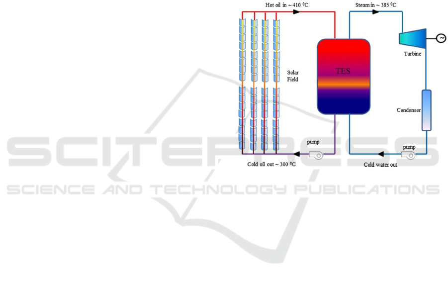
A schematic of a concentrated solar power plant
with TES is shown in Fig. 1. A single tank is used to
store energy which has a thermal gradient that
separates the hot fluid from cold fluid. Thus, a filler
material is used which acts as heat reservoir and also
replaces expensive HTF. A stratification of hot and
cold fluids in a thermocline tank prevents convective
mixing, which allows the maximum utilization of a
single tank. During the charge cycle, hot molten salt
from the collector field flows via from the top of into
the tank, which it loses heat to the filler material, and
finally exits the tank with a reduction in temperature
through the bottom of the tank and is back to the
collector field where further heating takes place.
Figure 1: Schematic of a concentrated solar power plant
with TES.
In this work, we present a mathematical model of
the CSP plants, which is integrated by developing a
program based on the method of characteristics.
Section 2 of this paper gives a brief overview of the
related works. Section 3 provides an overview of our
methodology. Section 4 concludes the paper and
provides an outlook into future work.
2.1 Mathematical Modeling
A comprehensive one-dimensional non-thermal
equilibrium model is used to investigate the energy
storage in a single tank thermocline storage system
assuming constant average velocity inside the bed.
The model is solved using method of characteristics,
which could produce numerical solutions of high
level of accuracy and stability with minimal
computing time [16].
Brinkman- Forchheimer extended Darcy model
is used to model the porous medium resistance.
The numerical model is simplified by
implementing the following assumptions:
ICCSRE 2018 - International Conference of Computer Science and Renewable Energies
292

A uniform radial distribution of the fluid flow
and rocks through the storage tank is
assumed to make the problem to a one
dimensional problem along the axis, z, of the
storage tank.
The axial conduction inside the packed bed is
neglected.
The flow is considered incompressible and
laminar.
Contacts between rocks are point contacts and
therefore heat conduction between rocks is
negligible.
There is no heat loss from the storage tank to
the surroundings.
The tank is considered to have a uniformly
distributed spherical filler materials of same
size as a porous matrix.
2.2 Governing Equations and
Boundary Conditions
2.2.1 Fluid Energy Balance Equation
Based on the aforementioned assumptions and by
performing a thermal energy balance on the control
volume, the energy balance equation for the fluid
and filler can be written as follows [16]:
The cross-sectional area of the tank associated to
the fluid flow is assumed constant at all points along
the axis of the tank and is:
(1)
With the flow velocity of U the thermal energy
balance of the fluid in the control volume dz is
giving by:
∁
(2)
Where the average fluid velocity in the packed bed
is:
(3)
With substitutions for the definition of enthalpy and
rearrangement of Eq. (2), the energy balance
equation becomes as:
∁
(4)
Introducing the following dimensionless variables:
;
(5)
∗
;
∗
(6)
The dimensionless governing equation for heat
transfer fluid can be expressed as:
∗
∗
(7)
where
∁
Based on Assumption (2), the heat transfer surface
area of rocks per unit length of the tank S
can be
calculated from the equation:
(8)
where d
is the equivalent diameter of rock (m) and
ε is the porosity.
The heat transfer coefficient h
Wm
⁄
in the
above equations is based on the analysis provided by
[17] for porous media.
0.191
∁
.
(9)
where the Re is the modified Reynolds number for
porous media, defined as [17]:
(10)
where G is the mass flux of fluid through the porous
bed expressed as:
(11)
and r
is defined at the characteristic radius by
[17] (sometimes defined as the hydraulic radius)
(12)
2.2.2 Energy Balance Equation for Filler
Material
For the energy balance of the filler material (rocks),
the same control volume dz was considered. The
filler works only to deliver/extract heat to/from the
passing fluid at the cost of a change in the internal
energy of the filler. The energy balance equation is
given by the following expression:
∁
1
(13)
with substitution of dimensionless variables given in
Eq. (5, 6), the above governing equation becomes as:
∗
(14)
where
∁
∁
The dimensionless form of governing equations will
also assist experimental test on a small-scale
prototype thermocline system, which only values of
and
need to be matched to a real-size
thermocline storage tank.
Numerical Investigation of Thermal Storage System in a Single-Tank for CSP Plants
293
3 METHOD OF
CHARACTERISTICS
3.1 Numerical Solution
The non dimensional energy balance equations for
heat transfer fluid and rocks can be solved
numerically along the characteristics [18]. Equation
(7) can be reduced along the characteristic t
∗
z
∗
,
so that we can have:
∗
(15)
Separating and integrating along the
characteristic,the equation becomes as:
∗
(16)
Similarly, Eq. (14) for the energy balance of rocks is
reposed along characteristic
∗
, so that
∗
(17)
The solution for Eq. (17) is very similar to that for
Eq. (15) but with an additional factor of H
. The
term H
is simply a fractional ratio of fluid heat
capacitance to rock heat capacitance. Therefore the
equation for solution of θ
will react with dampened
speed than θ
, as the filler material must have the
capacity to store the energy being delivered to it, and vice
versa.
Finally, separating and integrating along the
characteristic for Eq. (17) as:
∗
(18)
There are now two characteristic equations bound to
intersections of time and space. A discretized grid of
points, laid over the time space dimensions, will
have nodes at these intersecting points. Therefore,
Eq. (16) can be definitely integrated numerically as:
,
,
∗
,
,
(19)
The numerical integration of the right hand side is
performed via the trapezoidal rule and the solution
is expressed as follows:
,
,
,
,
,
,
∆
∗
(20)
where θ
,
is the value of θ
at v
,
and θ
,
is the
value of θ
at v
,
, and similarly so for θ
.
The integration for Eq. (18) along z
∗
const is:
,
,
∗
,
,
(21)
The numerical integration of the right hand side is
also performed via the trapezoidal rule and the
solution is given by:
,
,
,
,
,
,
∆
∗
(22)
Equations (20) and (22) can be reposed as a group of
algebraic equations for two unknowns of θ
,
and
θ
,
, while θ
and θ
at grid points v
,
and v
,
are
known will be demonstrated in the next work.
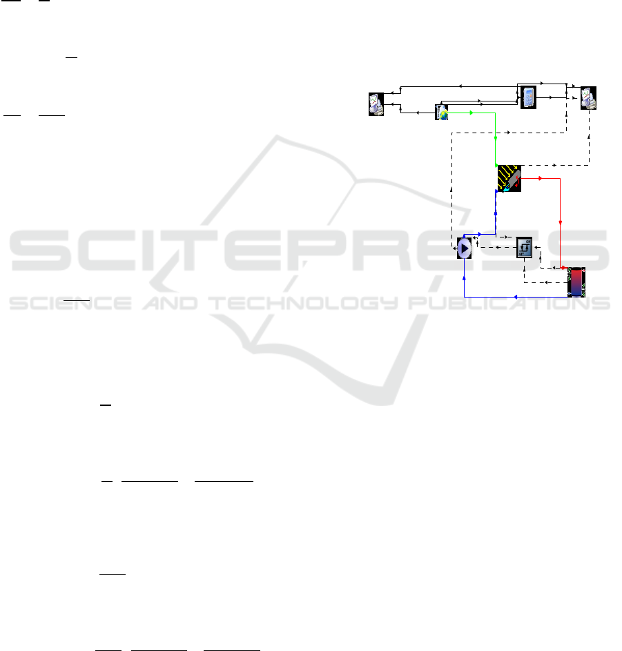
3.2 Simulation by TRNSYS
After its implementation in the TRNSYS16 TESS
library, the model (type 536), was integrated into an
evaluation project under different climatic zones in
Morocco.
We use the TRNSYS16 software to simulate the
prototype. All parameters of the CSP were
introduced in the TRNSYS model shown in Fig. 2.
Figure 2: Simulation by TRNSYS of a CSP plants with
Thermocline- Tank.
We use the TRNSYS16 software to simulate CSP
system using Solar Salt as the HTF in the first case.
According to the objective of the present study
that investigates the thermal performance of a
thermocline TES system for CSP plants under the
Moroccan meteorological data, the selected location
is Errachidia city, which is the second most
important insolation region in Morocco.
Fig. 3 shows the variation of the ambient
temperature and the wind velocity through out the
year for Errachidia site.
In the following section, the dynamic results are
presented during a representative week (first week of
July) and the variation of useful gain energy and
direct normal irradiation are summarized throughout
the year with different HTFs using in the first case
Solar Salt.
Weather Data
Pump2
Rergulation
Thermocline- tank
TRaceur graphe
CSP
Equa-2
TRaceur graphe-3
ICCSRE 2018 - International Conference of Computer Science and Renewable Energies
294
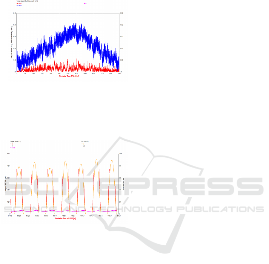
Figure 3: Annual ambient temperature and wind velocity
Fig. 4 shows the hourly variation of the outlet
temperature of the CSP collector. It can be observed
that HTF outlet temperature at the solar collector
varies periodically with time and its minimum value
can reach ambient temperature (Tamb) value during
de day time.
Figure 4: Variation of Solar Salt outlet temperature at the
collector (CSP) and ambient temperature during the first
week of July.
4 CONCLUSIONS
This paper describes a mathematical model of a
thermocline TES system, which is expected to be a
core technology for CSP plants.
A non-thermal equilibrium model is used for
investigating the effect of different HTFs on the
thermal performance of a thermocline thermal
energy storage system using Therminol, Solar Salt
and HITEC respectively as the HTFs and quartzite
rock as the filler material. As future work, we
prospect to study the performance and the simulation
of our mathematical model by TRNSYS software
and add the control of TES systems in the tank for
concentrated solar power plants. And we prospect to
study Thermal characteristics, including temperature
profiles and discharge effectiveness of storage tank.
In ordre to plot and to analyse charging and
discharging curves at different porosity values for
Therminol, Solar Salt and HITEC.
REFERENCES
D.C. Grogan, Development of Molten-Salt Heat Transfer
Fluid Technology for Parabolic Trough Solar Power
Plants-Public Final Technical Report, Abengoa Solar
LLC, 2013
M.Esen, T.Ayhan, Development of a model compatible
with solar assisted cylindrical energy storage tank and
variation of stored energy with time for different phase
change materials, Energy Convers.
Manage. 37 (12) (1996 1775–178.
M. Esen, A. Durmus, Geometric design of solar-aide latent
heat store depending on various parameters and phase
change materials, Solar Energy 62 (1) (1998) 19–28.
M.Karim, Experimental investigation of a stratified
chilled-water thermal storage system, App. Therm.
Eng. 31 (11) (2011) 1853-1860.
J. Nelson, A. Balakrishnan, S.S. Murthy. Experiments on
stratified chilled- water tank: expériences menées avec
des réservoirs d’accumulation d’eau galcée à
stratification, Int. J. Refrig. 22(3) (1999) 216- 234.
Z.Yang, S.V. Garimella, Thermal analysis of solar thermal
energy storage in a molten-salt thermocline, Solar
Energy 84 (6) (2010) 974–985.
C. Xu, Z. Wang, Y. He X. Li, F. Bai, Sensitivity analysis
of the numerical study on the thermal performance of
a packed-bed molten salt thermocline thermal storage
system, Appl. Energy 92 (2012)65–75.
M. Biencinto, R. Bayón, E. Rojas, L. González,
Simulation and assessment of operation strategies for
solar thermal power plants with a thermoclin storage
tank, Solar Energy 103 (2014) 456–472.
Z. Yang, S.V. Garimella, Molten-salt thermal energy
storage in thermoclines under different environmental
boundary conditions, Appl. Energy 87 (11) (2010)
3322–3329.
D. Brosseau, M. Edgar, J.W. Kelton, K. Chisman, D.
Ray, B. Emms, Testing of thermocline filler materials
and molten-salt heat fluids for thermal energy storage
systems in parabolic trough power plants, in: ASME
2004 International Solar Energy Conference,
American Society of Mechanical Engineers, 2004,
pp.587–595.
N. Calvet, J.C. Gomez, A. Faik, V.V. Roddatis, A. Meffre,
G.C. Glatzmaier, S. Doppiu, X. Py, Compatibility of a
post-industrial ceramic with nitrate molten salts for
use as filler material in a thermocline storage system,
Appl. Energy 109 (2013) 387–393.
C. Martin, N. Breidenbach, M. Eck, Screening and
analysis of potential filler materials for molten salt
thermocline storages, ASME 2014 8th International
Conference on Energy Sustainability collocated with
the ASME 2014 12th International Conference on Fuel
Numerical Investigation of Thermal Storage System in a Single-Tank for CSP Plants
295

Cell Science, Engineering and Technology, American
Society of Mechanical Engineers, 2014,
pp.V001T002A025V001T002A025.
J.E. Pacheco, S.K. Showalter, W.J. Kolb, Development of
a molten-salt thermocline thermal storage system for
parabolic trough plants, J. Solar Energy Eng. 124 (2)
(2002) 153–159.
D.H. Kim, S.H. Yoon, Y. Kim, C.H. Song, K.H. Lee J.S.
Choi. Experimental studies of the discharge
performance of single- medium TES for CSP
applications. App. Thermal. Engineering 127 (2017)
499-507.
K.S. Reddy, V. Jawahar, S. Sivakumar, T.K. Mallick
Performance investigation of single-tank thermocline
storage systems for CSP plants. Solar energy 144
(2017) 740-749.
Van Lew, J.T., Li, P., Chan, C.L., Karaki, W., Stephens,
J., 2011. Analysis of heat storage and delivery of a
thermocline tank having solid filler material. J. Sol.
Energy Eng. 133,021003.
Nellis, G,, and Klein, S,, 2009, Heat Transfer. Cambridge
University Press, Cambridge,
Polyanin, A, D,, 2002, Handbook of Linear Partial
Differential Equations for Engineers and Scientists.
Chapman and Hall, London/CRC,Boca Raton, FL.
ICCSRE 2018 - International Conference of Computer Science and Renewable Energies
296
