
Determination of Adequate Type of Stirling Engine for Cogeneration
in Industrial Sector
Kaoutar Laazaar, Noureddine Boutammachte
and Nadia Rassai
Department of Energy, ENSAM, Moulay Ismail University, Marjane 2 B.P. 15290 Al-Mansour, Meknès, Morocco
Keywords: Stirling Engine, Cogeneration, waste heat, cement plant, CHP.
Abstract: In the present paper, a comparison study of three types of Stirling Engine (Alpha, Beta and Gamma) was
realized for cogeneration purpose in industrial sector (cement plant). The different configurations of Stirling
engine are simulated by PROSA software. Several parameters are analysed such as working gas pressure,
engine speed, hot source temperature, cold source temperature and working fluid type. The results show that
the Alpha Stirling engine is the best type for integration in cogeneration system purpose due to its high overall
efficiency and output power, high compression ratio and low thermal losses.
1 INTRODUCTION
The depletion of fossil resources and their impact
on the environment impose an energy resolution,
which necessarily translates into a wide spread
application of energy efficiency and massive use of
renewable energies. Thus for the same comfort, we
can pay less energy bill thanks to concepts optimizing
the energy consumed and thus integrating the
principle of energy efficiency. It is in this context that
cogeneration (Combined Heat and Power, CHP)
systems are integrated to improve the efficiency of
industrial production processes. The Stirling Engine
(SE) is a promising technology for cogeneration since
it is an external combustion hot air engine, i.e. the
heat required for its operation can be from multiple
sources: solar energy, biomass, geothermal energy or
even industrial heat waste.
Existing works in the literature have treated
cogeneration with the SE only in residential building,
unfortunately no work has addressed the possibility
of integration SE in industrial sector for combined
production of heat and electricity (CHP).
The SE is classified in three types: Alpha, Beta
and Gamma, and each type is characterized by its
advantages and limitations. The choice of a particular
type for cogeneration requires preliminary study to be
able to integrate it into the industry in an efficient
way.
The aim of this work is the comparison between
Stirling engine types for determination of the best
configuration that deliver high output power and
overall efficiency and so improve the performance of
cogeneration based SE system.
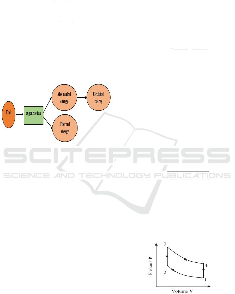
2 COGENERATION SYSTEM
The World Alliance for Decentralized Energy
(WADE) defines cogeneration as: «The process of
producing electricity and the useful thermal energy
(heat or cold) at high efficiency and close of the point
of use». The idea of cogeneration is based on the fact
that electricity generation releases a large amount of
heat usually dissipated in the environment. For this
reason, CHP techniques consist on recovering as
much as possible this residual and available thermal
energy.
The interest of cogeneration is the increase of
production system efficiency corresponding to a more
efficient use of primary energy resources.
Cogeneration systems can minimize energy losses,
reduce emissions and the investment price if the
system is well designed. Fig.1 shows the process of
cogeneration. CHP systems are distinguished from
traditional systems by their high overall efficiency,
Eq. (1) describes the efficiency of a traditional system
and Eq. (2) presents the overall efficiency of
cogeneration unit.
Laazaar, K., Boutammachte, N. and Rassai, N.
Determination of Adequate Type of Stirling Engine for Cogeneration in Industrial Sector.
DOI: 10.5220/0009773603690374
In Proceedings of the 1st International Conference of Computer Science and Renewable Energies (ICCSRE 2018), pages 369-374
ISBN: 978-989-758-431-2
Copyright
c
2020 by SCITEPRESS – Science and Technology Publications, Lda. All rights reserved
369
output
input
E
Q
(1)
output
overall
input
P
Q
(2)
Where
output
E
is generated electrical power in
KW
,
output
P
is generated electrical and thermal
powers in
KW
and
input
Q
is the fuel introduced into
the system input in
KW
.
Page Setup
The paper size must be set to A4 (210x297 mm). The
document margins must be the following:
Top: 3,3 cm;
Bottom: 4,2 cm;
Left: 2,6 cm;
Right: 2,6 cm.
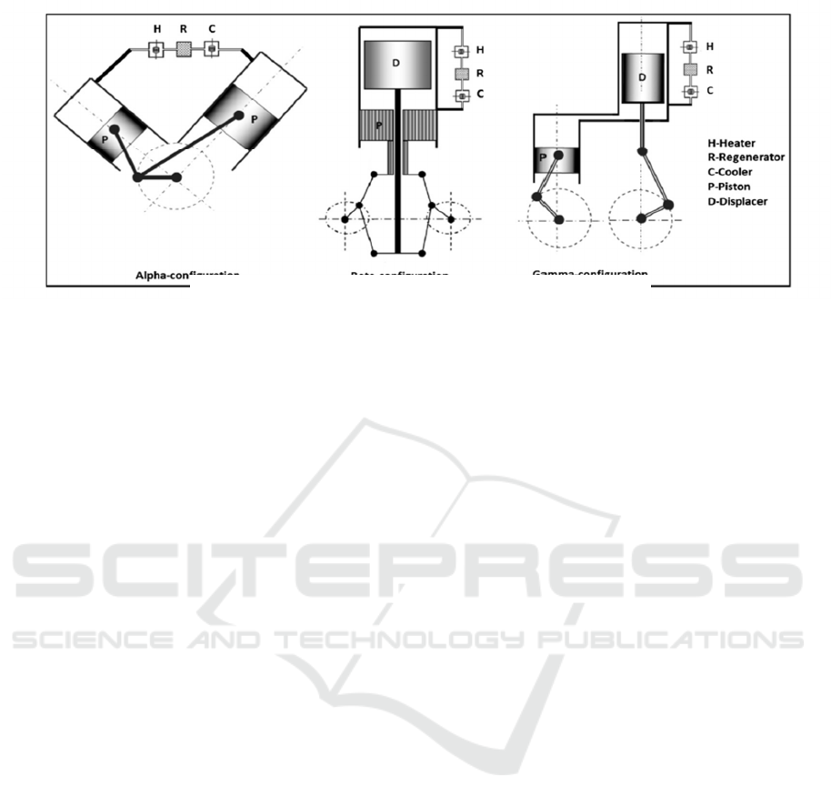
3 ANALYSIS OF THE STIRLING
ENGINE
3.1 Description of the Stirling Cycle
The Stirling engine (SE) is an external
combustion hot air engine, it was invented by the
Scottish clergyman and engineer Robert Stirling in
1816. The Stirling machine is a device that operates
in a closed cycle according to a thermodynamic cycle,
which in theory is described as a group of
thermodynamic processes comprising two isotherms
and two isochores. Fig.2 depicts the Pressure-Volume
(P-V) diagram of the Stirling cycle.
The area under P-V diagram presents the work
obtained from the operation of SE. As the Fig.2
shows, the cycle is divided into for processes:
- Process 1-2: Isothermal compression of
working fluid and release of heat to the
external source.
- Process 2-3: Isochoric heating given by the
regenerator to the system.
- Process 3-4: Isothermal expansion of
working fluid by introduction of the heat to
the engine from external source.
- Process 4-1: Isochoric cooling of the engine
and absorption of heat from the regenerator.
Theoretically, the efficiency of Stirling cycle is
the same as Carnot efficiency and is worth:
output
hl
stirling
input h
W
TT
QT
(3)
Where
output
W
is the output work in
W
,
input
Q
is
the input heat in W and
h
T
,
l
T
are the hot and cold
sources temperature respectively.
The output power of SE can be calculated
approximately from the Beale formula:
0.015
mp
P
pfV
(4)
Where
P is the output power of SE in
W
,
m
p is
the mean pressure in
bar ,
f is the frequency of the
cycle in
Hz and
p
V
is the displacement of the piston
in
3
cm .
The pressure of the SE is an important parameter
that is used for calculating the engine work, it is as
follows:
exp
1
reg comp
Ereg C
p
VVV
TT T
(5)
Where
p
is the pressure of Stirling engine,
exp
V
,
reg
V
and
comp
V
are expansion, regenerator and
compression space volumes respectively in
3
m ,
E
T ,
reg
T
and
C
T are expansion, regenerator and
compression spaces temperature in K.
Figure 1: Cogeneration process.
Figure 2: Stirling cycle diagram.
ICCSRE 2018 - International Conference of Computer Science and Renewable Energies
370
The SE differs from traditional engines by several
advantages such:
- Multi-fuel capability.
- High efficiency.
- Low operating noise.
- Low emissions.
3.2 Classification of the Stirling Engine
As mentioned before, there are three types of SE:
Alpha, Beta and Gamma, that are different by the
geometric configuration of each type as illustrated in
Fig.3.
The Alpha configuration has two pistons in hot
and cold cylinders respectively, it is a V-shape
formed by two pistons that are joined at the same
point on a crankshaft. The working fluid is moved
between the two pistons. A heater, regenerator and
cooler are grouped in series. The Alpha type can be
joined with a configuration of multiple cylinders,
hence a high power output can be reached, which is
adaptable with motorized machines.
The Beta configuration possesses a single
cylinder containing both a power piston and a
displacer that moves the working gas between the
cold and hot ends. This configuration is used with a
rhombic drive in general in order to keep the phase
angle difference between the power and displacer
pistons, but they may be joined on a crankshaft. Beta
type has less technical problems than the other types
because the power piston is away from the hot fluid.
The Gamma configuration has two separated
cylinders like Alpha configuration, but it possesses a
piston and displacer as the same as the Beta type, and
the pistons are joined in parallel on a crankshaft.
This configuration produces lower compression ratio
as the compression space is split up between the two
cylinders, but it is mechanically simpler than the other
configurations.
3.3 Application of the Stirling Engine
for Cogeneration in Cement Plants
Cement plants are a major source of heat ejection
that is lost in the air without any exploitation. In this
study, we are interested in the recovery of thermal
losses ejected by the process of clinker (cement
component) cooling leaving the kiln of cement plants.
The hot air generated from the cooling will be
recovered using a heat exchanger to be the heat source
of the SE which will simultaneously produce
electricity and heat for cogeneration purpose.
The specifications and operating conditions of
the SE types used in this study are summarized in
Table 1.
4 RESULTS AND DISCUSSION
4.1 Effect of Pressure
The pressure parameter has an important
influence on the operation of SE since it contributes
on the displacement of the working gas.
Figure 3: Diagram of Stirling engine configurations.
Determination of Adequate Type of Stirling Engine for Cogeneration in Industrial Sector
371
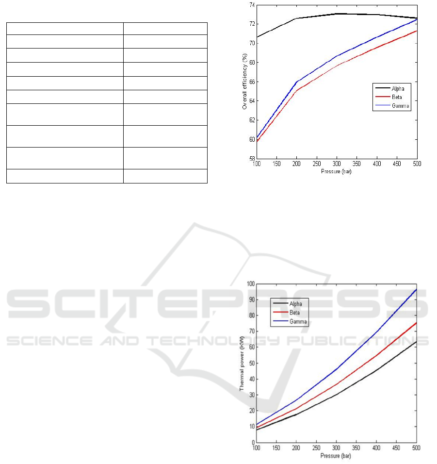
Table 1: Technical specifications of Stirling engine.
Parameters Values
Pressure (bar) 350
Hot source temperature (˚C) 1110
Cold source temperature (˚C) 61
Engine speed (rpm) 1500
Matrix outer diameter (mm) 104.24
Length of the cooler pipes
(mm)
220
Number of the cooler pipes (-
)
161
Length of the heater pipes
(mm)
246.3
Number of the heater pipes (-) 80
Fig.4 shows the pressure impact on the overall
efficiency, i.e. thermal and electrical efficiencies, for
the three types of SE. It is seen that the overall
efficiency increase as the pressure increase and reach
the values of 71.27 %, 72.46 % and 72.61 % for Beta,
Gamma and Alpha types respectively for 500 bar
value. The increase of overall efficiency for all the
types is due to the fact that the area under the P-V
diagram becomes larger at higher pressure which is
equal to power output. Hence the SE will produce
more power and it efficiency will increase. The Alpha
exceeds the other types in terms of overall efficiency
because it has a high compression ratio and its
pressure drop are low.
Fig.5 illustrates the influence of pressure on the
thermal power. It is shown that Gamma configuration
can produce more thermal power compared to the
other types. This is because Gamma type has more
heat losses so the cogeneration based SE system
recovers these thermal losses to generate thermal
power. However, the Alpha type produce more
electrical power so its overall efficiency is higher than
Beta and Gamma types as it is depicted in Fig.4.
4.2 Effect of Hot Temperature
The electrical efficiency for all SE types can be
improved when the temperature of hot source rises, as
displayed in Fig.6, and reaches maximum values of
50.88 %, 41.79 % and 40.32 for Alpha, Beta and
Gamma respectively at 1500 ˚C. It is due to the
Carnot efficiency equation which reveals that the
increase of hot temperature will improve the
efficiency, hence the output power will also increase.
Figure 4: Effect of pressure on overall efficiency.
The Alpha type remains the most powerful
configuration for CHP than the others, as the volumes
of hot and cold sources are separated, therefore it does
not release a lot of thermal losses and the input heat
is used properly.
Figure 5: Effect of pressure on thermal power.
4.3 Effect of Cold Temperature
As it is depicted in Fig.7, the performance of SE
decreases with the increase of the cold source unlike
that of the hot source. It can be seen that the efficiency
increases almost linearly for the three configurations
as long as the cooling temperature decreases and
reaches the values of: 46.07 %, 37.27 % and 34.45 %
for Alpha, Beta, Gamma respectively at 0 ˚C.
ICCSRE 2018 - International Conference of Computer Science and Renewable Energies
372
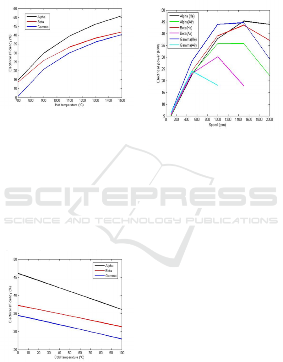
Figure 6: Effect of hot temperature on electrical efficiency.
This result is theoretically explained by the fact
that it is necessary to have a large temperature
difference between the hot and cold sources of the
Stirling engine to optimize its performance.
The efficiency of the Alpha engine exceeds that
of the other types because it is characterized by its
capability to operate with a large temperature
difference, which is the case of this study.
4.4 Effect of Engine Speed
Fig.8 compare the electrical power of SE with two
working fluid (Helium and Air) at different engine
speed values. The use of Helium as working gas
improve the output power because of its low heat
capacity and high thermal conductivity unlike Air.
Figure 7: Effect of cold temperature on electrical efficiency.
Figure 8: Effect of engine speed on electrical power.
The increase of electrical power at higher speed is
due to the repetition of the P-V cycle. However, the
rise of speed decreases the efficiency because of the
increase of the engine friction, so the heat exchange
between working gas and heat source does not happen
properly.
In high engine speed values (≥ 1500 rpm), the
Alpha SE provides high electrical power thanks to its
low dead volume and low friction in working space.
4.5 Effect of Thermal Losses on SE
Performance
In Fig.9, the thermal losses of three types of SE are
given for different pressure. It is noticed that the
thermal losses increase as the pressure increase. This
is due to leakage of piston rings, heat leak in the
conduct between the working gas and the hot source
and heat losses in regenerator of the SE.
The Gamma type has great thermal losses which
is owing to the no capability of this type to operate
with large temperature difference. Therefore, a lot of
heat input will be lost.
The Alpha SE remains the type that has the
minimum of thermal losses thanks to the fact that no
mixture between hot and cold working fluid is
performed.
The numerical results of this work simulation are
given in Table 2.
Determination of Adequate Type of Stirling Engine for Cogeneration in Industrial Sector
373
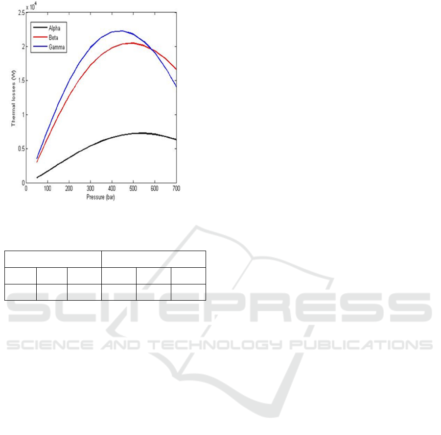
Figure 9: Thermal losses depending on the engine pressure.
Table 2: Numerical results of the comparison study
Electrical power (KW) Electrical efficiency (%)
Alpha Beta Gamma Alpha Beta Gamma
45.29 43.57 44.61 40.01 33.68 30.53
5 CONCLUSIONS
In the present work, a comparison study between
three types of Stirling engine for cogeneration
purpose in industrial sector (cement plant) is carried
out.
First, the influence of engine pressure on overall
efficiency and thermal power respectively was
analysed. The results show that Alpha type provides
the best overall efficiency thanks to its large
compression ratio. However, it does not provide the
best thermal power.
It is also noticed that the increase of hot source
temperature positively varies the efficiency of all
types, as it is necessary to apply a large temperature
difference between the hot and cold sources to
improve the engine performances. The results show
that Alpha type remains the best configuration for
industrial cogeneration due to its low thermal losses,
so the input heat is well used by the system.
The SE is optimized when Helium is utilized as
working gas because it has a high heat transfer
coefficient. It was found that the Alpha type can
provide high efficiency at high speeds due to its low
dead volume, hence the Stirling cycle can be repeated
several times without lot of mechanical friction.
The Alpha Stirling engine can generate a great
power output with high overall efficiency for
industrial cogeneration (cement plant in this study),
because of several advantages including high
compression ratio, low dead volume, separation of
hot and cold working gas spaces and capability of
operation in a high temperature difference.
REFERENCES
Wang, K., Sanders, S., Dubey, S., Choo, F. and Duan, F.
(2016). Stirling cycle engines for recovering low and
moderate temperature heat: A review. Renewable and
Sustainable Energy Reviews, 62, pp.89-108.
Ferreira, A., Nunes, M., Teixeira, J., Martins, L. and
Teixeira, S. (2016). Thermodynamic and economic
optimization of a solar-powered Stirling engine for
micro-cogeneration purposes. Energy, 111, pp.1-17.
Kaldehi, B., Keshavarz, A., Safaei Pirooz, A., Batooei, A.
and Ebrahimi, M. (2017). Designing a micro Stirling
engine for cleaner production of combined cooling
heating and power in residential sector of different
climates. Journal of Cleaner Production, 154, pp.502-
516.
Corria, M., Cobas, V. and Silva Lora, E. (2006).
Perspectives of Stirling engines use for distributed
generation in Brazil. Energy Policy, 34(18), pp.3402-
3408.
Thombare, D. and Verma, S. (2008). Technological
development in the Stirling cycle engines. Renewable
and Sustainable Energy Reviews, 12(1), pp.1-38.
Erol, D., Yaman, H. and Doğan, B. (2017). A review
development of rhombic drive mechanism used in the
Stirling engines. Renewable and Sustainable Energy
Reviews, 78, pp.1044-1067.
Kongtragool, B. and Wongwises, S. (2003). A review of
solar-powered Stirling engines and low temperature
differential Stirling engines. Renewable and
Sustainable Energy Reviews, 7(2), pp.131-154.
Alfarawi, S., AL-Dadah, R. and Mahmoud, S. (2016).
Enhanced thermodynamic modelling of a gamma-type
Stirling engine. Applied Thermal Engineering, 106,
pp.1380-1390.
Ahmadi, M., Ahmadi, M. and Pourfayaz, F. (2017).
Thermal models for analysis of performance of Stirling
engine: A review. Renewable and Sustainable Energy
Reviews, 68, pp.168-184.
ICCSRE 2018 - International Conference of Computer Science and Renewable Energies
374
