
Automatic Railway Barriers Security System Design using Inductive
Proximity Sensor based on Atmega 328
Eko Supraptono, Samsudi, I Made Sudana, Shohihatur Rohman, and Ervan Pradipta
Faculty of Engineering, Semarang State University, Indonesia
Keywords: Railroad Gate, Inductive Proximity Sensor, Arduino Uno
Abstract: The railroad-crossing gate is a safety measure for the passing train. Often accidents occur at the point of
railroad-crossing, due to the negligence of officers in opening the gate and bad ethics from other transportation
users. Therefore, it is necessary to use the automatic railroad-crossing gate as a security system. The automatic
railroad-crossing gate was made using a train imitation as a prototype of a real train, Atmega328
microcontroller, inductive proximity sensor and DC servo motor. The output of this device was opening and
closing the train door and the measurement of train speed. The experimental method was used in this study.
The observation was used to find out the results of train detection. In addition, the measurement of train speed
from the system was compared with manual measurement of speed. The tests were repeated for 10 times. The
automatic train crossbar was able to detect trains coated with metal, while the train which is not coated metal
could not be detected. The system was being able to display the measurement of the speed of the train.
However, there is a difference in the speed of manual calculation by the researcher as much as 1, 3 cm / s.
The difference was caused by the operation of the stopwatch in data collection process.
1 INTRODUCTION
In the modern era, technology is growing rapidly,
many technologies have been invented along with the
development of the era. The existing technology and
the newly invented technology can be combined to
produce more sophisticated technology to facilitate
human needs. In land transportation such as trains,
trains are rail transportation consisting of a series of
carriages pulled along the railroad to transport
passengers and goods. Train is classified as an
efficient land transportation, because it can transport
passengers and goods faster than other land
transportation.
Trains are a very influential land transportation in
the future, because trains are one of the land
transportation that is often used by the public.
According to data from the Central Bureau of
Statistics, 29,328 passengers were located in the
island of Java in December 2015 and has increased
every year, as of November 2017 train passengers
reached 33,798 passengers (bps.go.id).
The point of intersection of the road between the
railroads is commonly referred as the railroad -
crossing of a railway line, a railroad crossing that is
when the railroad intersects with the road (Regulation
of the Director General of Land Transportation
SK.770 / KA.401 / DRJD / 2005). The following is
data on railway level crossings on the island of Java
shown in Table 1.
Table 1. The list of level crossings on the island of
Java.
No. Partial Crossing Amount
1. Guarded Crossing 969
2. Unattended Crossing 2923
3. Wild Crossing 410
Total 4302
With the large number of the railroad - crossing
on the Java and the number of unattended and illegal
the crossing road, train accidents have become a
major factor at the level crossing.
Due to the number
of accidents that often occur at railway crossings, it is
necessary to create a railroad gate
to warn other land
transportation users, they
can stop before the railroad
gate to give the train a chance to run as stated in (Law
of the Republic of Indonesia No. 72 of 2009 regarding
Railway Traffic and Transportation).
The automatic
Supraptono, E., Samsudi, ., Sudana, I., Rohman, S. and Pradipta, E.
Automatic Railway Barriers Security System Design using Inductive Proximity Sensor based on Atmega 328.
DOI: 10.5220/0009011103410348
In Proceedings of the 7th Engineering International Conference on Education, Concept and Application on Green Technology (EIC 2018), pages 341-348
ISBN: 978-989-758-411-4
Copyright
c
2020 by SCITEPRESS – Science and Technology Publications, Lda. All rights reserved
341
railroad-crossing gate is not only to replace human’s
job as a crossing guard, but also to reduce the costs
that must be incurred
for the salary of the crossing
road guard.
The automatic railroad-crossing gate is
also prioritized to maintain railroad crossings without
guard posts.
The previous studies on the automatic
railroad-crossing gate have used the automatic
railroad-crossing gate using infrared sensors (Sarnia
and Yusnita, 2015),
(Kumar et al., 2017),
(Krishnamurthi et al., 2015), (More et al., 2015),
(Pangestu., 2017: 282-291).
Detection using
ultrasonic sensors has also been performed (Firdaus,
2016) and optocoupler sensors (Santoso et al., 2013),
(Banuchandar et al., 2012).
Furthermore, the motion
detection has also been installed on the detection
system (Fayyadh et al., 2015). The results of the
detection of infrared and ultrasonic sensors are very
sensitive. Therefore, it has not been optimal in
detecting trains.
While, the results of detection using
motion detection are not optimal because the results
of the study are affected by the condition of light.
With some shortcomings of the previous studies
which are very sensitive to passing objects, sensors
that can detect trains specifically metal or iron to
detect trains are needed, because most cars passing
the railroad are made of metal or iron, with that
The
research employed proximity inductive sensors
atmega328. This present study investigated these
following aspects:
1. Proximity sensor as a detection of train arrival, so
that train detection can be more specific (can only
detect objects made of metal)
2. Train speed measurement system as the
information for vehicles crossing the railroad.
The aim of this study was to design a more specific
train detection system.
2 METHOD
The experimental method was employed in this
study.
According to Jaedun (2011: 5), the
experimental method is causal study whose evidence
is obtained through comparison / comparison
between these following things:
a. The experimental group (which receives treatment)
with the control group (which does not receive
treatment);
or
b. Subject condition before being given treatment
with after being given treatment.
Experimental study is also a study conducted
intentionally by researchers
by giving a certain
treatment / to the subject of the study in order to
generate an event / situation that was examined what
are the consequences.
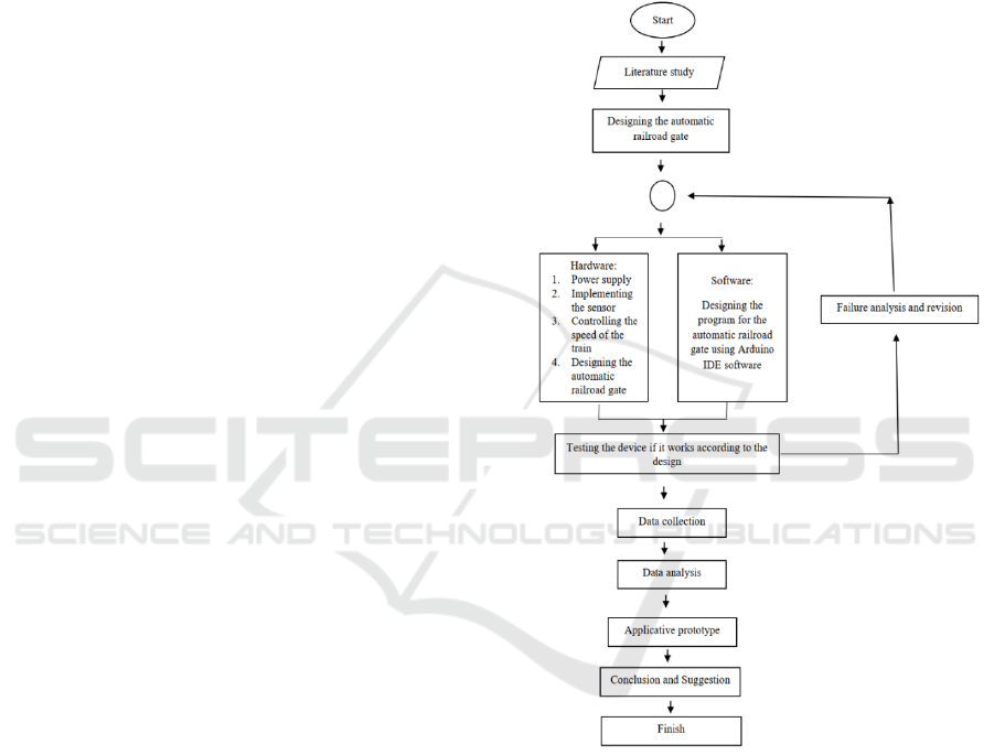
The procedure of this study can
be seen in Figure 1.
Figure 1: the procedure of the study.
2.1 Arduino Uno
Arduino Uno is an arduino board that uses an
ATmega328 microcontroller.
The Arduino Uno has
14 digital pins (6 pins can be used as PWM outputs),
6 analog inputs, a 16 MHz crystal oscillator, a USB
connection, a power supply connector, an ICSP
header, and a reset button.
Arduino Uno uses
ATmega16U2 which is programmed as a USB-to-
serial converter for serial communication to a
EIC 2018 - The 7th Engineering International Conference (EIC), Engineering International Conference on Education, Concept and
Application on Green Technology
342
computer via a USB port.
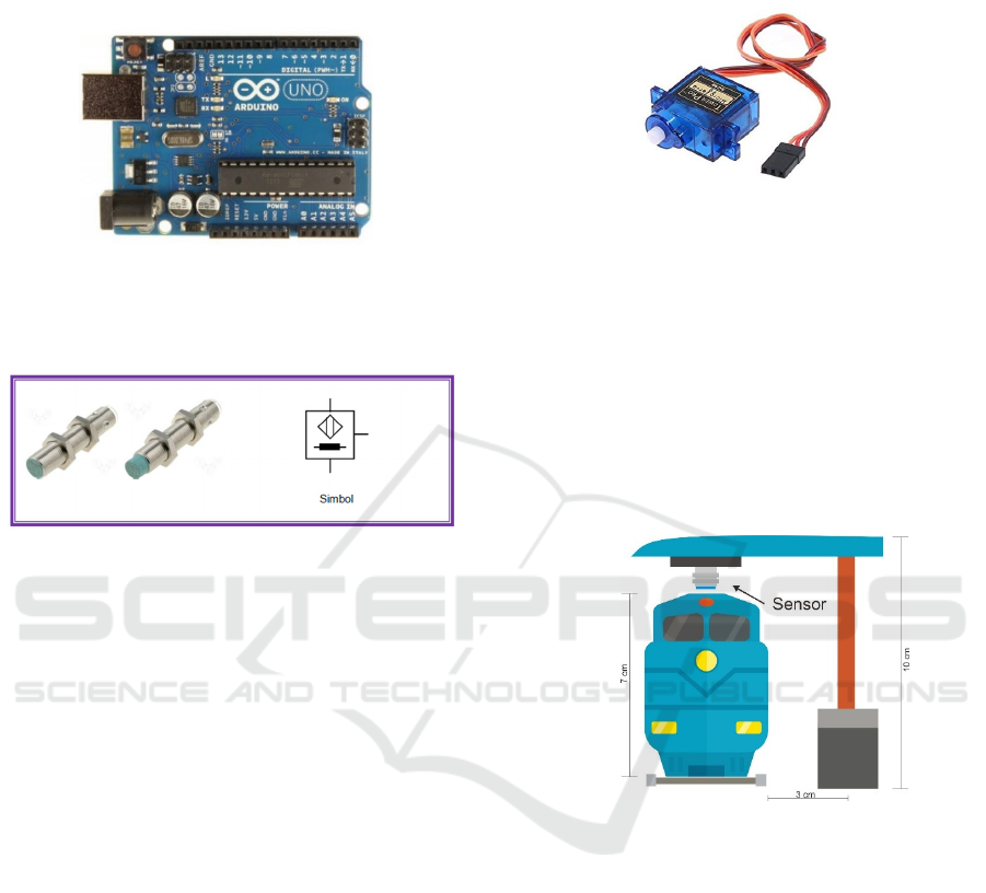
The physical form of
arduino uno is shown in Figure 2 (Suyatno et al:
2017).
Figure 2: Arduino uno.
2.2 Inductive Proximity Sensors
Figure 3 Inductive proximity sensor.
The detection of the presence of
a
train employed an inductive proximity
sensor.
The inductive proximity sensor combined an
electromagnetic coil used to detect the presence of a
conductive metal object.
The sensor ignored the
objects that were not of metal.
An inductive sensor as
shown in Figure 3 is a non-contact electronic
switch.
Inductive sensors are used to detect metals
and graphite. Sensors were used for these following
things: monitoring and measuring speed speed,
sensing the final position and pulses of engine
rotation (Miftahu, 2013: 258-261)
.
2.3 DC Servo Motor
Servo motors are DC motors as appeared in
Figure 4 that have high quality.
This motor was
equipped with a control system.
In its application,
servo motors were often used as closed loop controls.
As a consequence, they can handle position changes
accurately as well as speed and acceleration
settings.
Servo motor wiring system consisted of
three parts: Vcc, Gnd, and Control (PWM).
(Dr.
Widodo Budiharto, 2013: 81-82)
Figure 4 DC Servo Motor.
2.4 Sensor Placement Design
Figure 5 shows the sensor placement design.
The sensor design placement to the passing train, the
inductive proximity sensor was placed on top of the
bar and faced the ground. Therefore, the sensor did
not get
interference from other objects which caused
the railroad crossing bar to close even though there
were not trains passing by,
the
sensor placement design can be seen in figure 5.
Figure 5 Sensor placement design.
2.5 The Design of the Railway
The security system design of the railway-
crossing bar employed
a mock train as the
object, using
three inductive proximity sensors as
the main sensors.
Each sensor had a distance from the
railway-crossing bar and each function for the
system.
The door bar will be driven by a DC servo
motor, the design of the design can be seen as shown
in Figure
6.
Automatic Railway Barriers Security System Design using Inductive Proximity Sensor based on Atmega 328
343
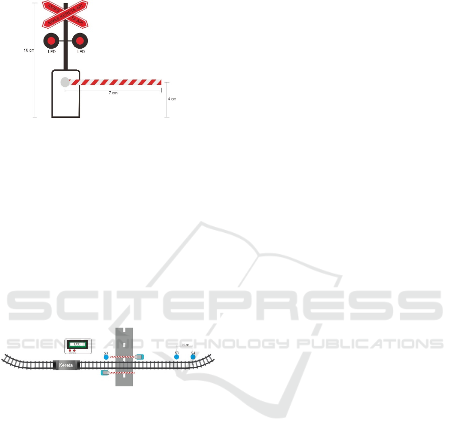
Figure 6: The design of the door bar
2.6 Railroad-crossing Bar Design
The railroad - crossing bar as appeared in Figure
7 was the safeguard used at a railway crossing to close
the train track.
According to the Regulation of the
Director General of Land Transportation SK.770 /
KA.401 / DRJD / 2005, the railroad - crossing bar
must be equipped with
1. A flashing red LED signal or two red LED lights
that turn one alternately,
2. The sound signals or sign on lights that indicate
the direction of the train’s arrival.
Figure 7. The design of railroad-crossings in this
study.
3 RESULT AND DISCUSSION
The design of the system in this study consisted of
the manual and automatic system. The design of
manual system can open and close the railroad gate
according to the command of the manual button.
The
automatic design system can work automatically
without the need for commands from the humans or
guard of the railroad – crossings. The railroad –
crossing gate can open
and close automatically
using
three inductive proximity sensors.
The design of the automatic railroad – crossing
gate had two railroad tracks that expand for 30 cm,
and have two railroad tracks that form a semicircle
with the diameter of 36 cm.
So, the length of the
railroad track can be calculated by the following
formula:
The length of track = 30 × 2 + π × d
= 60 + 3.14 × 72
= 286 cm
Circling the railroad tracks with the length of 286
cm took around 13 seconds. Therefore, the train speed
can be determined as follows:
v = s / t → 286/13 = 22 cm / s
To operate the automatic system, the distance of
the sensor placement to the railroad crossing gate
must be determined, with the waiting time of the
system after the train is detected by sensor 1 until it
reaches the gate for 5 seconds, with a train speed of
22 cm / s,
then the distance of the sensor placement
can be calculated as follows:
s = v × t → 22 × 5 = 110 cm
The distance of 110 cm is a predetermined
distance from the railroad gate until the placement of
the first sensor. The time for the detection of the first
sensor 1 until the second sensor was 1.5 seconds. The
time required for the railroad-crossing bar closed until
the train reached the railroad-crossing bar was 3.5
seconds.
The distance of the sensor placement to the
crossing of the actual train crossing with the fastest
train on the island of Java is 80 km / hour based on
the data on train-api.info page (22 April 2015). The
website shows that the speed of the fastest trains
operating on the island Java is Argo Sindoro train
(Gambir - Semarang) with the speed of 445 km / h.
The train took within 5 hours 30 minutes from
Gambir to Semarang.
The desired time when sensor
1 detects the train is 5 minutes. It takes 1 minute 30
seconds for the sensor to detect the train, and 3
minutes 30 seconds then the train reaches the train
crossing. The sensor placement can be determined as
follows:
Sensor 1 detects trains
t = 5 minutes = 0.083
then, s = v × t → 80 × 0.083 = 6.64 km
EIC 2018 - The 7th Engineering International Conference (EIC), Engineering International Conference on Education, Concept and
Application on Green Technology
344
Sensor 2 detects trains
t = 3 minutes 30 seconds = 0.058
then, s = v × t → 80 × 0.058 = 4.64 km
then from the calculation of the formula it can
be seen that the distance between sensor 1 and sensor
2 is 2 km.
3.1 Functional Test Results of the
Inductive Proximity Sensor
Functional test of inductive proximity sensor
aims to determine the level of accuracy of the
sensors in detecting trains.
The tests were
conducted 20 times. 10 tests used metal-coated
trains and 10 tests used non - metal coated
trains.
Each test was carried out by giving
a
different distance between the sensor and the
train.
Different distances between sensors and
trains were aimed to find out the maximum range
of the inductive proximity sensor. Table 2 shows
functional test results of the inductive proximity
sensor.
Table 2. Functional Test Results of the
Inductive
Proximity Sensor.
No.
Distance Train Detection
results
1. 0.1 mm Metal coated Detected
2. 0.1 mm Without
metal
Not detected
3. 0.2 mm Metal coated Detected
4 0.2 mm Without
metal
Not detected
5. 0.3 mm Metal coated Detected
6. 0.3 mm Without
metal
Not detected
7. 0.4 mm Metal coated Detected
8. 0.4 mm Without
metal
Not detected
9. 0.5 mm Metal coated Not detected
10 0.5 mm Without
metal
Not detected
11. 0.6 mm Metal coated Not detected
12 0.6 mm Without
metal
Not detected
13. 0.7 mm Metal coated Not detected
14. 0.7 mm Without
metal
Not detected
15. 0.8 mm Metal coated Not detected
16. 0.8 mm Without
metal
Not detected
No.
Distance Train Detection
results
17. 0.9 mm Metal coated Not detected
18. 0.9 mm Without
metal
Not detected
19. 1 cm Metal coated Not detected
20. 1 cm Without
metal
Not detected
3.2 The Functional Speed Test Results
and Train Speed Measurements
The functional tests of the train’s speed and speed
measurements were performed to determine the speed
control performance and if the train speed
measurement can function properly. Potentiometer
10 K 10 has been installed on the toy train, the testing
was performed for 10 times by changing the
predetermined resistance values: 10 KΩ, 9 KΩ, 8 KΩ,
7 KΩ, 6 KΩ, 5 KΩ, 4 KΩ, 3 KΩ, 2 KΩ, 1 KΩ on the
potentiometer to determine the difference in speed.
The functional test of train speed measurement
was conducted by using the design that has been
designed to detect train speed. This test was
conducted to determine the accuracy of the system in
measuring the speed of the train. The train
speed measurements generated from the system were
compared to the manual train speed measurement
using the calculation of this following formula v =
௦
௧
where s is the predetermined distance, the distance
between sensor 1 and sensor 2 is 30 cm, while t is the
time taken by the train to travel from sensor 1 to
sensor 2, in the calculation of the travel time from
sensor 1 to sensor 2 manually, the resulting time was
taken using the stopwatch. Table 3 shows the results.
Automatic Railway Barriers Security System Design using Inductive Proximity Sensor based on Atmega 328
345
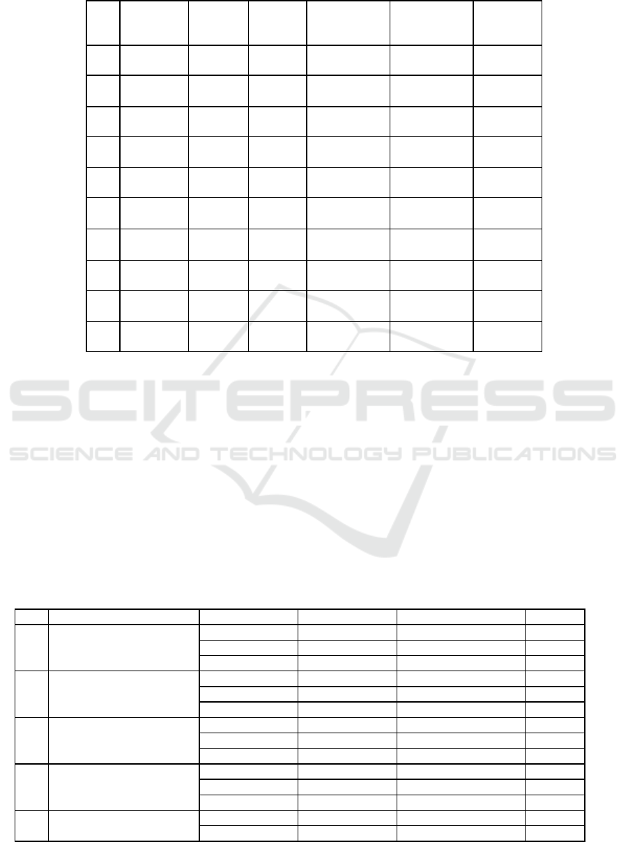
Table 3. The Results of speed testing and train speed measurement.
No. Resistance
Voltage
(Theory)
Voltage
(system)
Speed
Measurement
(theory)
Speed
Measurement
(system)
Difference
1 10 KΩ 3 V 2.9 V 22 cm / s 21.7 cm / s 0.3 cm / s
2 9 KΩ 2.7 V 2.7 V 20.5 cm / s 20.4 cm / s 0.1 cm / s
3 8 KΩ 2.4 V 2.4 V 19.3 cm / s 19.5 cm / s 0.2 cm / s
4 7 KΩ 2.1 V 2 V 18 cm / s 18 cm / s 0 cm / s
5 6 KΩ 1.8 V 1.7 V 16.9 cm / s 16.7 cm / s 0.2 cm / s
6 5 KΩ 1.5 V 1.5 V 15.2 cm / s 15.1 cm / s 0.1 cm / s
7 4 KΩ 1.2 V 1.2 V 14.5 cm / s 14.5 cm / s 0 cm / s
8 3 KΩ 0.9 V 0.8 V 13 cm / s 12.9 cm / s 0.1 cm / s
9 2 KΩ 0.6 V 0.6 V 12 cm / s 11.9 cm / s 0.1 cm / s
10 1 KΩ 0.3 V 0.3 V 10.5 cm / s 10.7 cm / s
0.2 cm /
s
3.3 The Results of the Performance Test
of the Design System
Testing of the design of the automatic railroad –
crossing gate system was an overall test of the design
system.
The testing of the design was conducted to
determine the performance of the automatic railroad
– crossing gate system. The overall design testing
was
carried out by running the system according to
the program, namely by passing the train through
sensor 1, sensor 2, and sensor 3 by testing it for 10
times with a fixed and unidirectional train speed.
This
test was conducted to find out the feasibility of
the
automatic railroad – crossing gate system. The result
of the performance test of the design system
explained in Table 4.
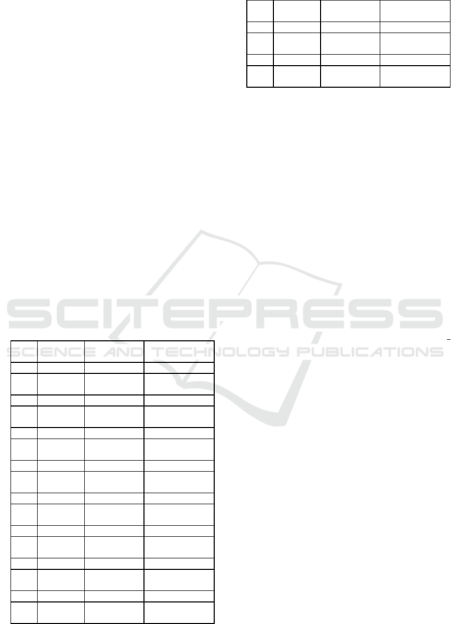
Table
4. Test results of the Work Design system.
No. Train Condition Train passes The gate system LCD display Buzzer
1. Metal – coated Trains
Sensor 1 Open "Watch out for trains" ON
Sensor 2 Closed "Train speed" ON
Sensor 3 Open "Please walk" OFF
2. Non Metal – coated Trains
Sensor 1 Open "Train crossing" OFF
Sensor 2 Open "Train crossing" OFF
Sensor 3 Open "Train crossing" OFF
3. Metal – coated Trains
Sensor 1 Open "Watch out for trains" ON
Sensor 2 Closed "Train speed" ON
Sensor 3 Open "Please walk" OFF
4 Non Metal – coated Trains
Sensor 1 Open "Train crossing" OFF
Sensor 2 Open "Train crossing" OFF
Sensor 3 Open "Train crossing" OFF
5. Metal – coated Trains
Sensor 1 Open "Watch out for trains" ON
Sensor 2 Closed "Train speed" ON
EIC 2018 - The 7th Engineering International Conference (EIC), Engineering International Conference on Education, Concept and
Application on Green Technology
346
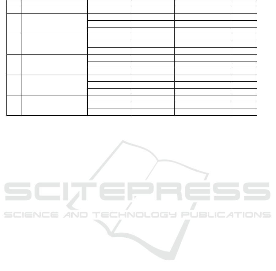
No. Train Condition Train passes The gate system LCD display Buzzer
Sensor 3 Open "Please walk" OFF
6. Non Metal – coated Trains
Sensor 1 Open "Train crossing" OFF
Sensor 2 Open "Train crossing" OFF
Sensor 3 Open "Train crossing" OFF
7. Metal – coated Trains
Sensor 1 Open "Watch out for trains" ON
Sensor 2 Closed "Train speed" ON
Sensor 3 Open "Please walk" OFF
8. Non metal – coated Trains
Sensor 1 Open "Train crossing" OFF
Sensor 2 Open "Train crossing" OFF
Sensor 3 Open "Train crossing" OFF
9. Metal – coated Trains
Sensor 1 Open "Watch out for trains" ON
Sensor 2 Closed "Train speed" ON
Sensor 3 Open "Please walk" OFF
10 Non Metal – coated Trains
Sensor 1 Open "Train crossing" OFF
Sensor 2 Open "Train crossing" OFF
Sensor 3 Open "Train crossing" OFF
3.4 Discussion of the Functional Test
Results of Inductive Proximity Sensors
The results of the functional test of inductive
proximity sensor showed that the inductive proximity
sensor can only detect objects made of metal. While,
the sensor cannot detect the passing train that was not
coated with a metal.
The inductive proximity sensor
could only work with the distance of sensor to the
train = 0.1 mm - 0.4 mm, at a distance of 0.5 mm - 1
cm inductive proximity sensor could not detect the
train. Therefore, the maximum detection distance of
the inductive proximity sensor is 0.4 mm.
This
detection distance in line with the datasheet on the
inductive proximity sensor which stated that the
sensor can only detect metal objects with a maximum
detection distance of 0.4 mm.
3.5 Discussion of Functional Test
Results of Speed and Train Speed
Measurement
From the data regarding train speed control,
the results showed that the train could be controlled
by using a potentiometer.
The test was performed by
varying the potentiometer resistance value from the
highest resistance value to the lowest resistance
value, the train speed can change from fast to
slow.
From the results of train speed testing, the
highest train speed was at 10 KΩ potentiometer
resistance, a voltage on a dc motor of 3 V and has a
measured system speed of 21.7 cm / s with the
theoretically measured speed is 22 cm/s. On the other
hand, the lowest train speed is at 1 KΩ, the voltage on
the dc motor is 0.3 V and has a speed of 11 cm / s
while the theoretical measurement is 10.9 cm / s.
The test on the train speed measurement
revealed that there is a difference in the error on the
train speed measurements measured by the system
with the theoretical train speed measurement.
The
average of difference in the measurement results by
the system and theory is 1.3 cm / s.
The difference
from the results was obtained from the calculation of
the speed formula using the sensor then it was
inputted into the program and processed by arduino
uno microcontroller compared to theoretical speed
measurement by using a
stopwatch. The difference
was caused by the operation of the
stopwatch during
the manual train speed measurement.
3.6 Discussion of Research Results of
the Overall Performance of the
Design
The results of study revealed that the automatic
railroad-crossing gate could work according to the
expected system design.
The test was carried out by
using a metal-coated and a non metal – coated train
for 10 times.
The automatic railroad-crossing gate
opened and closed the gate manually and
automatically according to the programmed system.
The system could only detect the metal-coated trains.
When sensor 1 detected the train then the buzzer
was
active. The system started calculating the travel time
of the train until it reacheed sensor 2 and the LCD
displayed "watch for the train". When sensor 2
detected the train, it began calculating the travel time
from sensor 1 to sensor 2 and started opening the gate
and LCD displayed the results of train speed
measurement as "Train speed". When sensor 3
detected a train, the system waited until the train was
not detected as a sign the train has passed, then the
Automatic Railway Barriers Security System Design using Inductive Proximity Sensor based on Atmega 328
347

gate of the railroad - crossing opened and the LCD
displayed "please walk".
4 CONCLUSIONS
The design of the automatic railroad – crossing gate
using inductive proximity sensors based on
atmega328 could perform optimally. The results of
the inductive proximity sensor test showed that sensor
detection can only detect metal – coated object and
the maximum detection distance is only 4 mm. The
results of adjusting the train speed using a
potentiometer can also work well and the train speed
measurement system obtained more accurate results
compared to manual calculations. The results showed
that the system and manual speed measurements had
an average difference of 1.3 cm / s. The overall
performance testing of the design system showed that
the system could work optimally. This design has a
manual operation to open the gate manually when you
want to open the gate manually during a system
failure.
REFERENCES
Banuchandar, J., et al. 2012. Automated Unmanned
Railway Level Crossing System. International Journal
of Modern Engineering Research (IJMER) Vol 2(1), pp
458-463.
Budiharjo, S., dan Putra, R. S. Rancang Bangun Model
Perahu Mini Robot Pembersih Sampah di Sungai
Menggunakan Android Berbasis Arduino Uno. Jurnal
ICT Penelitian dan Penerapan Teknologi.
Budiharto, W., 2013. Robotika Modern Teori dan
Implementasi. Edisi Revisi. Yogyakarta: Andi
Yogyakarta.
Fayyadh, M., Sunarya, U., dan Nugraha, R. 2015.
Perancangan Sistem Otomatisasi Palang Pintu Kereta
Api Berbasis Motion Detection. e-Proceeding of
Engineering Vol 2(1), pp 291-297.
Firdaus, M. A., dan Utomo, A. B. 2016. Miniatur Palang
Pintu Kereta Api Otomatis dengan Menaampilkan
Kecepatan Kereta Serta Waktu Tunggu Menggunakan
Arduino. Jurnal Teknik Elektro Vol 8(1).
Krishnamurthi, K., et al. 2015. Sensor Based Automatic
Control of Railway Gates. International Journal of
Advanced Research in Computer Engineering &
technology (IJARCET) Vol 4(2), pp 539-543.
Kumar, M. P., Naveen K., dan Kumar, M. R. 2017.
Automatic Railway Gate Controller. International
Jounal of Science.
More, S. R., et al. Intelligent Railway Crossing Gate
Control with High Speed Anti-Collision Alerting
System. International Journal of Computer
Applications, pp 12-15.
Oktareza, S. R., dan Rahayu Y. 2015. Simulasi Sistem
Keamanan Palang Pintu Perlintasan Kereta Api
menggunakan LabVIEW. Jurnal Teknik Elektro
Universitas Riau Vol 2(2).
Pangestu, B. P., Prasetio, B. H., dan Setyawan, G. E. 2017.
Implementasi Kendali Palang Pintu Kereta Api
menggunakan IR Sensor dan NRF24L01. Jurnal
pengembangan Teknologi Informasi dan Ilmu
Komputer Vol 1(4), pp 282-291.
Santoso, A. B., Martinus, dan Sugiyanto. 2013. Pembuatan
Otomasi Pengaturan Kereta Api, Pengereman, dan
Palang Pintu pada Rel Kereta Api Mainan Berbasis
Mikrokontroler. Jurnal FEMA Vol 1(1).
Soleh, M. 2013. Teknik Kontrol. Edisi Pertama. Jakarta:
Kementerian Pendidikan dan Kebudayaan Republik
Indonesia.
EIC 2018 - The 7th Engineering International Conference (EIC), Engineering International Conference on Education, Concept and
Application on Green Technology
348
