
Improving the Performance of a Small-Scale Wind Turbine System
Saiful Huda
1
, Prastyono Eko Pambudi
2
and Sudarsono
1
1
Department of Mechanical Engineering, Institut Sains & Teknologi AKPRIND Yogyakarta, Indonesia
2
Department of Electrical Engineering, Institut Sains & Teknologi AKPRIND Yogyakarta, Indonesia
Keywords: Improving Performance, Blades, Hubs, A Small-Scale Turbine System
Abstract: This research aims to improve the performance of a small-scale wind turbine system. It is done by varying the
inertia energy through designing different wights of hubs and blades. One is heavy blades with light hub and
the other is a light blade with the heavy hub. The assumption is that the starting point of the blade to run will
be at the lower wind speed due to the smaller torsion moment. However, when the blades have run, the turbine
gets the power from the centrifugal post stored in the hub. The research result shows that both sets of blades
and hubs produce relatively the same power, that is 12 watts. The difference is on the speed of the wind to run
the turbine. The one with the lighter blade and heavier hub start running at 3 m/s and the other is that of 4m/s.
The conclusion is that the use of the lighter blade and heavier hub is effective to improve the performance of
a small-scale turbine system.
1 INTRODUCTION
Indonesia is an archipelago country with 2/3 of its
territory is the ocean and has the longest coastline in
the world (± 81,000 km), located on the equator line,
and has more than 17,000 islands. Under these
circumstances, wind energy is a potential that must be
developed and utilized. Based on LAPAN data
(Daryanto, et al., 2005), wind in Indonesia has
varying speeds but generally is categorized as low-
speed winds.
The utilization of wind energy sources as a power
plant is one of the efforts to meet the needs of electric
energy, which is increasing in the number of needs
for households, industries, and commercials. Wind
power generation can be developed as alternative
energy, which is renewable and environmentally
friendly. To develop this potential, we need a tool to
convert the kinetic energy of the wind into electrical
energy in the form of a windmill that works to rotate
an electric generator. This research study the
performance test of windmill propeller with blade
material from wood composite with flax fiber
reinforcement. The windmill model used in this study
is a propeller type windmill with a comparison of the
number of blade 5 which is made of wood as core
material (a type of balsa wood) with hemp fiber and
the polymer matrix. Data retrieval on the windmill is
done in two ways, first from the generator, and the
second is mechanical power by measuring the torque
and speed of the spinning shaft rotation (rpm)
Wind speeds in Indonesia are not as big as in
countries like the Netherlands that have used
windmill energy. The wind speed around the southern
coast of Yogyakarta ranges from 3-5 meters per
second. So it needs to be combined with low-speed
generators and solar thermal energy. Alternative
energy is acknowledged to be still difficult to replace
conventional energy, but at least renewable energy
can be a supporting energy, especially for areas that
have not been electrified.
Research by Wakui, et al. (2002) compared three
types of windmills, namely Savonius-Darius, Darius,
and horizontal shaft two winder types of propellers.
The results showed that the combination of Savonius
Darius had the advantage of being able to start
independently compared to Darius even though there
was a decrease in the quantity of output power. The
propeller horizontal windmills have a large power
output, with a note they must have a good Yaw
mechanism to respond to wind direction
Research to determine the speeds characteristic
range of the wind machines and to make easy the
choice of the suitable wind turbine for a given site, in
order to maximize the delivered energy for a given
amount of available wind energy has done by
Bencherif et. al (2014).
Huda, S., Pambudi, P. and Sudarsono, .
Improving the Performance of a Small-Scale Wind Turbine System.
DOI: 10.5220/0009006900930098
In Proceedings of the 7th Engineering International Conference on Education, Concept and Application on Green Technology (EIC 2018), pages 93-98
ISBN: 978-989-758-411-4
Copyright
c
2020 by SCITEPRESS – Science and Technology Publications, Lda. All rights reserved
93

The results of Setiawan's research (2016) show
that the change in pitch angle of the two H-type
Darrieus wind turbine blades affects the power
produced by wind turbines in real wind conditions.
The greater the pitch angle, the lower the power
produced. Changes in pitch angle also affect the
efficiency of wind turbines in real wind conditions.
The more pitch angle increases the greater the
efficiency. Purwono's research (2016) states that
there is a significant difference in the average power
produced by NACA 3412 Vertical Axis Windmill
(KASV) at 5% real level and there is a tendency that
the increased wind speed and number of blades used
will increase the power produced by KASV.
The airfoil used for the turbine blade base profile
is the airfoil through which low-velocity winds
(maximum 10 m/s) flow, so the lift ratio parameter to
the maximum drag force becomes the focus of
developing airfoil characteristics for wind turbines
with a wind speed range of 0-10 m / s (Timmer and
Rooij, 2003). Timmer and Rooij (2003) also stated
that in the early 1980s to 1990, profiles that were
widely used as the basic form of wind turbine blades
were airfoils developed by NASA which were given
4-digit NACA codes (NACA 44xx series) and 5-digit
NACA (NACA 63xxx series ). Parezanovic, et. al
(2005) state that the most important aspect of wind
turbines is their aerodynamic effectiveness, the base
of which is the design of the airfoils forming the
blades. It is possible to predict airfoil performance by
using commercial CFD programs, and furthermore, to
design new airfoils with better performance, based on
those predictions.
At present, windmill propellers, which were
previously made from metal materials, have begun to
be made from GFRP (glass fiber reinforced plastic)
skin composite materials. From previous studies, it is
known that the Sengon Laut Wood (Albizia falcata)
has a high tensile stress and buckling stress.
Meanwhile, hemp has a high tensile stress and impact
strength as well. The sandwich composite structure
has the ability to withstand a greater load than that of
the lamina composite (Sudarsono, 2013). The
description above shows that the windmill propeller
engineering from the GFRP skin composite needs to
be developed into a composite structure in order to be
able to withstand external loads (collisions) and have
a lightweight to easily rotate when blown in the wind.
In this study, a composite sandwich with balsa wood
and hemp fiber will be developed as a reinforcement
for propeller-making raw materials. Testing will also
be done to determine the effect of the position
/location of the center of gravity (C.G) of blade and
hub on the performance of the windmill. The variable
of the center of gravity of the windmill is obtained by
making the windmill hub and blade different in
weights. The first hub was made of Aluminum
material whereas the second one used AISI 1030 steel
material. While the windmill blade was made from
composite using glass fiber while the other was made
from composite using balsa wood core and hemp
natural fiber, this way the different weight of the hub
and blade were obtained.
2 METHOD
This research was conducted to determine the
effect of the position/location of the center of gravity
/ C.G blade and hub on the performance of the
windmill. This was done by observing the power
generated by the windmill and the wind speed needed
for the initial round of the windmill. The variable
location of the center of the windmill is obtained by
making the windmill hub and blade have different
weights. The first hub was made of Aluminum, while
the second used AISI 1030 steel material. The first
windmill blade was made from composite using glass
fiber and the second was made from composite using
balsa wood core and hemp natural fiber, this way the
different weight of the hub and blade were obtained.
Forces that work on C.G. windmill blades due to
wind flow theoretically consist of tangential force t,
axial force a and centrifugal force S. The different
position of C.G. will result in the different T torque
produced by the windmill. This is because the
distance of the tangential force t to the axle weight
point is different so that a different P Power is
produced assuming the windmill shaft rotation is the
same. A different T torque will also affect the initial
rotation of the windmill in which theoretically for the
same wind speeds the torque of C.G. which is farther
from the center of the shaft axis will be bigger so that
at the farther the CG, the windmill will rotate at a
lower wind speed.
The kinetic energy of K rotation is a function of
the mass of a rotating object and angular velocity, by
making a mass variable from the hub and blade, the
rotational kinetic energy produced by the windmill
also changes. In this research, a hub made of steel
with a weight of 550 g and aluminum with a weight
of 320 g was made. The windmill blade is made of
fiberglass composite which has a weight of 300 gr and
a composite with balsa wood core and hemp fiber that
weighs 280 gr. Both are made according to the NACA
4415 standard. The distance between the C.G. and the
center of the axis for the blade made of fiberglass is
EIC 2018 - The 7th Engineering International Conference (EIC), Engineering International Conference on Education, Concept and
Application on Green Technology
94
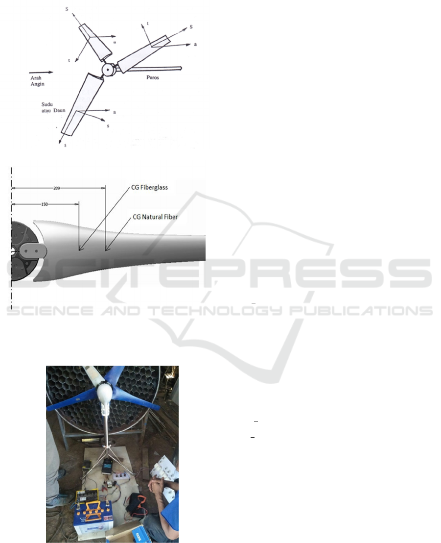
150 mm while the blade made of natural fiber with a
balsa wood core is 209 mm.
(a)
(b)
Figure 1: (a) Forces that work on C.G. and (b)
location of C.G on a windmill blade.
Figure 2: Measurement of electrical power and
mechanical power.
In order to find out the power generated by the
windmill, electrical power is tested by using an AC
generator and mechanical power testing using torque
meters. While wind energy is obtained from a simple
wind tunnel that is specifically designed (figure 2).
3 RESULTS AND DISCUSSION
The data to determine the performance of the
windmill in this research were obtained using two
different methods, first, by finding the relationship
between wind speed and electrical power produced
by windmill generators, while the second is finding
the relationship between wind speed and mechanical
power produced by the windmill using a torque tester.
This is done to determine the possibility of a
generator performance that is not optimum. The test
results are presented in the following discussion.
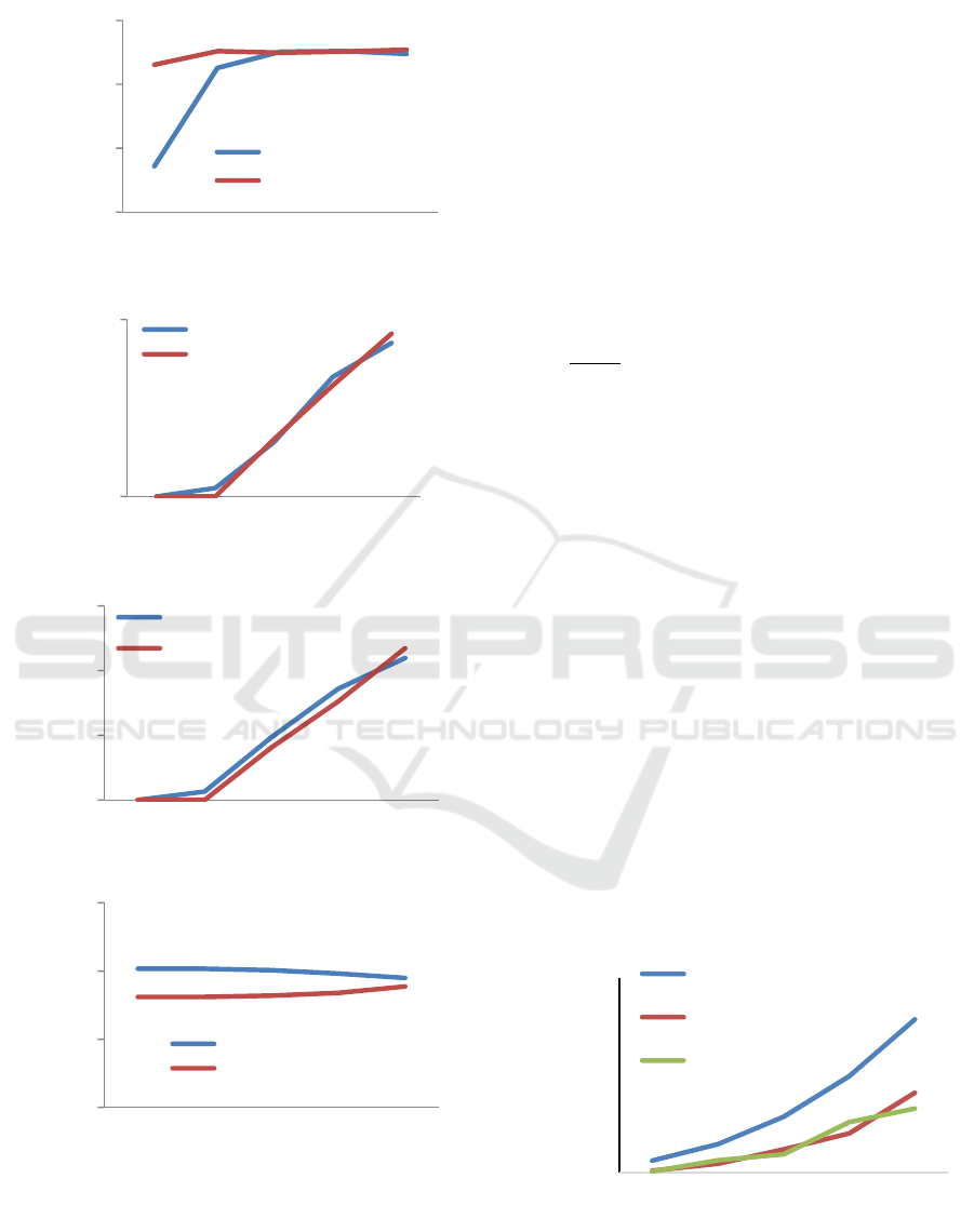
3.1 Electrical Power Testing
Figure 3 (a) shows that blades made of natural
fibers with lighter weight at 3 m / s wind speed can
produce a voltage of 22 V. While heavier blades are
only able to produce a voltage of 7 V even though the
wind power produced is equal. This is consistent with
the following [Yeni Yusuf Tonglolangi, 2014]:
W =
ρ A V
3
watt ……………………..(1)
Where : W = Wind Energy watt , ρ = Air density
(kg / m
3
), A = Wind catching area (m
2
) and V = Wind
Speed (m / s).
This shows that the lighter blade has a better
initial rotation because of the tangential force
generated by the wind at the beginning of the rotation
of the windmill against the smaller blade weight with
smaller kinetic energy. This is in accordance with the
following equation.
I
……………………………..(2)
m
……………………...(3)
Where V is the wind speed m / s, while m is the period
of rotating objects in kg. At larger wind speeds with
the same air density will produce greater power as the
following wind power equation: 0.5
watt ……………………...(4)
Where P is wind power (watts), ρ is wind density
(Kg / m
3
), A is the section of the wind channel (m
2
)
and V is the wind speed (m / s). With wind density in
Yogyakarta [Kifli, 2016] of 1.17 kg / m
3
, wind power
of W is 157.5 watt, so the power produced as in
Figure 3 (c) has very low efficiency, both for the
blade made of glass fiber and natural fiber both have
Improving the Performance of a Small-Scale Wind Turbine System
95
(a)
(b)
(c)
(d)
Figure 3: The results of the windmill electrical power
test versus (a) Voltage (b) Electric Current (c) Power
output (d) Energy.
almost the same performance. The total efficiency of
a wind turbine can be calculated using the equation: γ
= P / W x 100%; so that for wind speeds of 7 m / s
turbine efficiency γ is 8%.
3.2 Mechanical Power
Mechanization factors. In order to know the parts that
cause the low efficiency of wind turbines, whether
turbine generators or mechanical factors of
windmills, mechanical efficiency is calculated by
comparing the wind power and the shaft mechanical
power produced by the windmill. The mechanical
power of the Pm shaft is calculated based on the
equation:
watt
……………………...(5)
where :
T = Torque N-m
n = Shaft Rotate rpm
Mechanical power on the shaft generated by
windmills with blades made of glass fiber and that of
made of natural fibers is relatively the same. At a
wind speed of 6 m / s glass fiber blade has a power
(P) of 40 watt, while the blade of natural fiber has a
power of 52 watt. While at wind speeds of 7 m / s
fiberglass fiber blades produce 80 watts of power, and
natural fiber blades produce 65 watt of power. Wind
power at wind speeds of 6 m / s and 7 m / s are 85
watt and 157 watt respectively, so the average
mechanical efficiency of windmills is 50.1%, much
higher than the efficiency of wind turbines using
electric generator windmill. Figure 4 shows the
results of mechanical tests of power and wind speed
relations.
Figure 4: Results of mechanical tests of power and
wind speed relations.
0
10
20
30
34567
Voltage (V)
WindSpeed(m/s)
FiberglassBlade
NaturalFibreBlade
0
0.5
34567
ElectricCurrent
(Ampere)
WindSpeed(m/s)
FiberglassBlade
NaturalFibreBlade
0
5
10
15
34567
Power (watt)
WindSpeed (m/s)
FibreglassBlade
NaturalFibreBlade
0
5
10
15
34567
Energy(Watt/jam)
WindSpeed(m/s)
FibreglassBlade
NaturalFibre…
0
100
200
34567
Power(watt)
WindSpeed(m/s)
WindSpeedvsPowerOutput
WindPower
PowerofFiberglassBlade
PowerofNaturalFibre
Blade
EIC 2018 - The 7th Engineering International Conference (EIC), Engineering International Conference on Education, Concept and
Application on Green Technology
96

3.3 Torque and Windmill Rotation
The rotational kinetic energy of an object that rotates
depends on the angular velocity ω radians / second
and the magnitude of the moment of inertia I Kg. m
2
of the object. Rotational kinetic energy can be
calculated using the equation:
I
……………………………(6)
(a)
(b)
Figure 5: Results of mechanical tests of rotational
speed, torque, and wind speed relations.
Figure 5 (a) and (b) shows that the rotational speed of
the glass fiber blade can achieve greater rotation at
the same wind speed when compared to blade from
natural fiber, this occurs because the blade of glass
fiber has a higher weight so that the rotational kinetic
energy is greater and more stable at higher speed and
wind speed. On the other hand, the torque produced
is higher in the blade with natural fiber than the blade
using glass fiber.
4 CONCLUSIONS
The test results show that at a wind speed of 3 m / s
the blade made of natural fiber produces a voltage of
22 V while the blade of glass fiber produces a voltage
of 7 V. This indicates that the lighter blade has a
better initial rotation, due to the tangential force the
wind was generated at the beginning of the rotation of
windmills against the smaller blade weight with less
kinetic energy.
The speed of the glass fiber blade can achieve greater
rotation at the same wind speed when compared to the
blade of natural fiber, at the same wind speed of 7 m
/ s, RPM of the fiberglass blade is 3.600 rpm. While
natural fiber blade is 2.500 rpm. This happens
because the blade of glass fiber is heavier so that the
rotational kinetic energy is larger and more stable at
higher speeds and wind speeds. On the other hand, the
torque produced is higher in the blade with natural
fiber than that of the blade using glass fiber. From the
results of the analysis, a conclusion can be drawn that
the blades made of natural fiber have a better
performance than the blades made of glass fiber.
ACKNOWLEDGMENTS
Our thanks go to the Directorate General of Higher
Education, Ministry of Research Technology and
Higher Education, which has funded research
activities in accordance with the Letter Agreement
Research Assignment Number: 02/SPP/LPPM/
PL/II/2018, through Applied Product Research
Competitive Grant funds.
REFERENCES
Bencherif, M., Brahmi, B.N.,Chikhaoui, 2014. A. Optimal
selection of Wind Turbine Generators, International
Journal of Computer Applications, 92, 1-10.
0
0.5
1
1.5
2
2.5
3
34567
Torque(N.m)
WindSpeed(m/s)
TorquevsWindSpeed
PowerofFiberglassBlade
PowerofNaturalFibreBlade
0
500
1000
1500
2000
2500
3000
3500
4000
34567
RotationalSpeed(rpm)
WindSpeed(m/s)
RotationalSpeedvsWindSpeed
PowerofFiberglassBlade
PowerofNaturalFibreBlade
Improving the Performance of a Small-Scale Wind Turbine System
97

Daryanto, Y., F. A. Yohannes, F. Hasim, 2005. Potensi,
Peluang dan Tantangan Energi Angin di Indonesia,,
BPPT Tangerang.
Kifli, M.D., 2016. Analisa Pengaruh Massa Jenis Udara
Terhadap Pengujian Labu Ukur, Thesis, Universitas
Gadjah Mada.
Ostowari C. and Naik D., 1985. Post-Stall Wind Tunnel
Data for NACA 44XX Series Airfoil Sections, U.S.
Department of Energy.
Parezanovic, V., Rasuo B., Adzic, M., 2005. Design of
Airfoils for Wind Turbine Blades, University of
Belgrade, Belgrade, Serbia, pp. 192-200.
Purwono, B.S.A, Masroni, Muqit, A.,2017. Strategi
Pemanfaatan Kincir Angin Sumbu Vertikal Type
NACA 3412, Prosiding Seminar Nasional Teknik
Mesin Politeknik Negeri Jakarta, pp. 533-541
Ria, M., 2018.https://www.matadunia.id/ 2016/01/sumber-
daya-energi-angin.html, (accessed on 25 July 2018)
Rooij, R.V & Timmer, N., 2004. Design of Airfoils for Wind
Turbine Blades, Delft University of Technology, The
Netherlands.
Setiawan, I.B., 2016, Pengaruh Perubahan Sudut Pitch Pada
Blade Terhadap Kinerja Turbin Angin Darrieus Tipe-H
Dua Tingkat Dengan Pengarah Angin Pada Kondisi
Angin Real, Jurnal Teknik Mesin, 04, 267-273.
Sudarsono, 2013. “Optimasi Rancangan Kincir Angin
Modifikasi Standar NACA 4415 Menggunakan Serat
Rami dengan Core Kayu Sengon Laut Yang Tahan
Terhadap Iklim Pesisir Pantai Pandansimo”, Disertasi,
Universitas Diponegoro,.
Wakui, T., & Hashizume, T., 2001. “Optimal Operating
Method of the Wind Turbine-Generator Systems
Matching the Wind Condition and Wind Turbine Type”,
Waseda University. Japan.
Wakui, T., Tanzawa, Yoshiaki & Hashizume, Takumi &
Outa, Eisuke & Usui, Akira, 2000. Optimum Method
of Operating the Wind Turbine-Generator Systems
Matching the Wind Condition and Wind Turbine
Type. Proceedings of the World Renewable Energy
Congress-VI. 4. 2348-2351.
EIC 2018 - The 7th Engineering International Conference (EIC), Engineering International Conference on Education, Concept and
Application on Green Technology
98
