
Optimization of CNC Milling Machining Time through Variation of
Machine Parameters and Toolpath Strategy in Various
Cross-sectional Shape on Tool Steels and Die Steels Materials
Wirawan Sumbodo, Kriswanto, Murdani, Idhhar Suwanda and Tri Syamsul Allam
Department of Mechanical Engineering, Universitas Negeri Semarang, Semarang, Indonesia
idharsuwanda3@gmail.com, syamsul165@yahoo.com
Keywords: Machine Time, Simulation, Toolpath Strategy, Optimization.
Abstract: CNC machines are manufacturing machines for mass products that required to operate quickly. Machining
Time efficiency will reduce production costs. This paper presents an optimization of CNC milling Machining
Time from a variations of machine parameters, toolpath strategy and variations in cross sectional shapes. The
method is simulation use simulation software and optimization with constraint machining time. The program
is based on parameters (speed, feed rate, and width of cut) for pocket roughing operations. The cross section
shape of the workpiece is rectangular with 5 variation size. The width of cut for roughing work is 30%, 50%,
and 80%. Endmill uses a diameter of 12 mm and 4 flutes. The optimal machining time value in each cross
section workpiece is generated from the zigzag toolpath strategy and 80% width of cut. The optimum
Machining Time of W1 is 3 minutes 11 seconds, W2 is 5 minutes 55 seconds, W3 is 12 minutes 25 seconds,
W4 is 5 minutes 18 seconds and w5 is 12 minutes 19 seconds. The toolpath strategy that produces the largest
Machining Time high speed and true spirals toolpath strategy.
1 INTRODUCTION
Computer Numeric Control machine (CNC) is a
manufacturing machine technology widely used in
industries. CNC machine is used to produce high-
precision mass products quickly. CNC machines with
high capability produce products quickly called high
speed machine (HSM) CNC machines. The HSM
milling machine has a spindle speed of up to
60,000rpm. High speed machining is one of the
modern technologies that increases the efficiency,
accuracy and quality of workpiece compared to
conventional cutting (Awale, 2015). CNC milling
machines generally have spindle speeds of 3000 rpm
to 6000 rpm. CNC machines with high spindle rates
can produce high feed rate and small machine time.
Small Machining Time is the efficiency of production
time which reduces production costs. Machining time
estimation is a critical step towards an optimal and
practical production plan (Borkar, 2014). Gavril
(2016) study about increase productivity and cost
optimization in CNC manufacturing with the results
that by increasing the working time by 32.49% may
achieve an economy up to 10.33% for the
manufacturing cost.
The milling CNC machine with a small spindle
rate so that the feed rate produced is small while the
Machining Time is large. Parameters that affect the
value of Machining Time other than spindle rate and
feed rate are stepover and toolpath strategies.
Determination of stepover parameters and
toolpath strategies affects machine time. (Romero,
2013), and (Gologlu, 2008). Dimitrov (2012), Saroj
(2013), Daneshmand (2013), Prajapati (2013), and
Minquiza (2013) study of the reduction in Machining
Time CNC milling, the results show that setting
toolpath parameters using the help of CAM software
can reduce machining time. These parameters include
speed, stepover percentage, feed rate, and toolpath
strategy. Daneshmand (2011) investigating potential
ways to reduce Machining Time with the help of
CATIA
®
and CAM, the results of machining time are
reached when using a zigzag toolpath strategy. Study
on Machining Time by Akmal (2013) shows that the
parallel spiral toolpath strategy has the smallest
Machining Time compared to other toolpath
strategies by reason of a parallel spiral strategy using
84
Sumbodo, W., Kriswanto, ., Murdani, ., Suwanda, I. and Allam, T.
Optimization of CNC Milling Machining Time through Variation of Machine Parameters and Toolpath Strategy in Various Cross-sectional Shape on Tool Steels and Die Steels Materials.
DOI: 10.5220/0009006800840092
In Proceedings of the 7th Engineering International Conference on Education, Concept and Application on Green Technology (EIC 2018), pages 84-92
ISBN: 978-989-758-411-4
Copyright
c
2020 by SCITEPRESS – Science and Technology Publications, Lda. All rights reserved
a down milling process when cutting. Prajapati
(2013) study of toolpath optimization for turbine
blades in VMC machines with MasterCAM
®
software resulting in significantly reduced Machining
Time and tool paths depending on the workpiece
geometry (designed) and cutting conditions.
This paper presents an optimization Machining
Time resulting from variations in speed, feed rate,
stepover, tollpath strategy from various cross section
workpieces of tool steels and die steel materials. The
Machining Time of each variation was obtained by
simulation using CAM software and CNC simulation
software. CAM software makes it possible to achieve
and simulate manufacturing processes to check the
correctness of a project before it is implemented
(Gavril, 2016). This study also aims to get optimal
parameters so that CNC machines with low spindle
speed specifications (max 3000 rpm) can produce the
fastest machine time.
2 METHOD
This research method is simulation and optimization.
Simulation of program and Machining Time using
CAM software and CNC Simulation software. CAM
(Computer Aided Manufacturing) software is used to
generate CNC programs by setting the parameters of
speed, feed rate, steopover (Width of cut) and
toolpath strategy on variations in the cross section of
the workpiece. The CAM process uses MasterCAM
X4 software on a CNC milling machine. CNC
Simulation Software to simulate programs so that
Machining Time is obtained. The simulation software
used is SSCNC (Swansoft CNC Simulation) with a
Fanuc Oi-M system. Parameters of speed, feed rate,
and steopover are calculated for machining of the tool
steels and die steels materials.
The limit of parameters calculating in this study is
cutting roughing with a width of cut (WoC) 30%,
50% and 80% of the tool diameter. The tool used is a
12 mm diameter flat endmill 4 flutes with material of
TiAN coated carbide (Titanium Aluminum Nitride).
Table 1: Data of speed and feed rate for tool steels and die
steels (Guhring, 2015).
WoC (%)
Speed (SFM)
Feed rate (IPT)
30
300
0.024
50
200
0.022
80
200
0.022
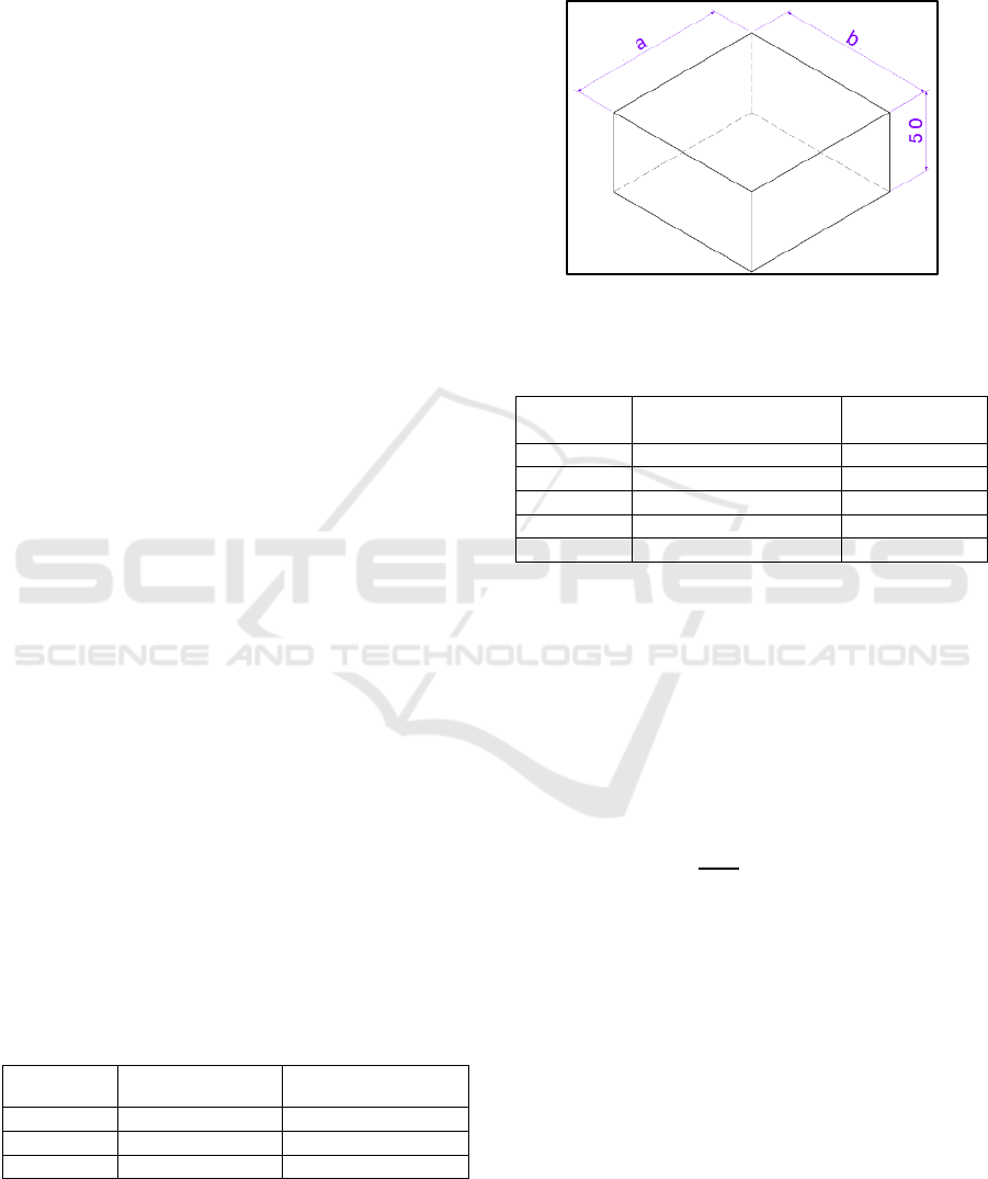
The cross-sectional design of the workpiece
consists of 5 variations which are generally used in
mold and die products. The shape of the rectangular
cross section is varied with the comparison of the
sides as in Table 2. The design of the workpiece and
the dimensions are shown Figure 1.
Figure 1: Shape and geometry of the cross section of the
workpiece.
Table 2: Variations in the sizes of cross section shapes.
Workpiece
Code
Sides Comparison
(a:b)
Size (mm)
W1
1:1
100:100
W2
1:2
100:200
W3
1:4
100:400
W4
2:1
200:100
W5
4:1
400:100
Spindle speed in SFM is converted in RPM units
using equation 1. Selection of SFM using WoC is
30%, 50%, and 80% which is the WoC criterion for
roughing cutting. Feed rate is calculated using IPT
data Table 1 then converted to IPM units (Inch per
Minutes) according to equation 2. Feed rate in IPT is
converted to units of mm / minute using equation 3.
Dept of Cut (DoC) uses standard DoC for roughing
with values 0,5 d1.
RPM =
SFM
d1
x 3.82
(1)
IPM = z x IPT x RPM
(2)
mm/min = IPM x 25,4
(3)
Where SFM the Surface Feet minutes, RPM the
Rotation Per Minutes, IPM is Inch per Minute, IPT is
Inch per teeth, and z is number of flute/teeth. IPT
value on WoC is 30% multiplied by factor 1.1 while
in WOC 50% and 80% multiplied by 1.
Table 3 is the result of speed calculation (RPM),
feed rate (mm / min), and width of cut (mm) on
stepover 30%, 50%, and 80% . Data speed and feed
rate on the WoC 50% and 80% have the same value,
even though the WoC dimension is different. The
same speed value is obtained from the same SFM
Optimization of CNC Milling Machining Time through Variation of Machine Parameters and Toolpath Strategy in Various Cross-sectional
Shape on Tool Steels and Die Steels Materials
85
which is 200, while the feed rate (IPT) value is
obtained the same because multiplied by a factor of 1.
Table 3: Results of calculation speed, feed rate, and width
of cut.
Width of Cut
Speed
(SFM)
Feed rate
(IPT)
Speed
(RPM)
Feed rate
mm/min)
%
mm
30
3.6
300
0.024
2426
596
50
6.0
200
0.022
1617
361
80
9.6
200
0.022
1617
361
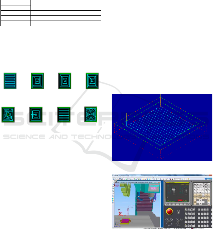
The number of variations in toolpath strategy in
CAM software is 8 namely zigzag, constant overlap
spiral, parallel spiral, parallel spiral clean corners,
morph spirals, high speed, one way and true spirals.
The toolpath strategy variation is coded TS1 to TS8.
The toolpath strategy parameter is found in pocketing
work. The design toolpath strategy is shown Figure 2.
Figure 2: Toolpath strategy.
Machining Time simulation results in each cross
section of the workpiece are optimized by constraint
the value of the Machining Time below 15 minutes.
The most optimum Machining Time is the smallest /
lowest Machining Time data from various shapes of
cross section workpieces.
3 RESULTS AND DISCUSSIONS
NC program was created base on machine parameters
data in speed, feed rate, and width of cut appropriate
table 3 for tool steels and die steels. A variety of
toolpath strategies (TS1.d. TS8) in sequence are
zigzags, constant overlap spirals, parallel spirals,
parallel spiral clean corners, morph spirals, high
speed, one way and true spirals.
3.1 Optimization Machining Time of
W1 Workpiece
The cross section of the W1 workpiece is a square
with a sizes of 100 mm x 100 mm as shown Figure 3.
Figure 3 is a cutting of the zigzag toolpath on the
workpiece. The results of the simulation Machining
Time of the W1 workpiece are shown in Table 4.
SCNC software simulation shown in Figure 4.
Machining Time simulation using this SSCNC
software generates same value as the actual machine.
This study does not use the Machining Time value of
MasterCAM but uses Machining Time from SSCNC.
Setting the SSCNC software according to the actual
machine is set spindle speed and feed rate at 100%
work. Prajapati (2013) found that, there is a deviation
of MasterCAM software simulation time with
experimental machining time may be due to time
required for tool change in the CNC machine. This
study did not replace the cutting tools to make
workpieces, while in the study Prajapati replaced
cutting tools.
Figure 3: Zigzag toolpath on W1 workpiece.
Figure 4: Simulation in CAM software.
Machining time simulation results in the cross
section of the W1 workpiece show that the fastest
Machining Time of various WoC and toolpath
strategy variations is 80% WoC on TS1 (Zigzag)
Zigzag
Constant
Overlap Spiral
Parallel
Spiral
Parallel Spiral
Clean corners
Morph
Spiral
High
Speed
One
Way
True
Spiral
EIC 2018 - The 7th Engineering International Conference (EIC), Engineering International Conference on Education, Concept and
Application on Green Technology
86
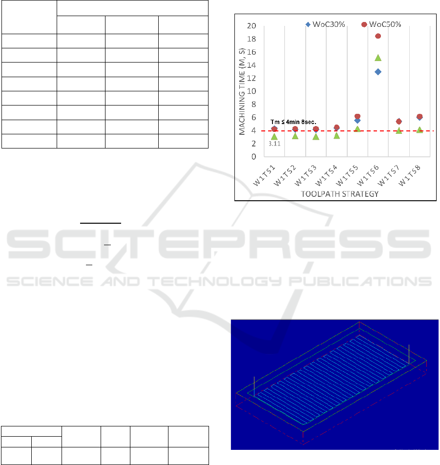
which is 3 minutes 11 seconds. The longest
Machining Time (slow) is 50% WoC with TS6 (high
speed) which is 18 minutes 45 seconds.
Table 4: Machining Time of W1 workpiece.
Variation
Machining Time (minute, seconds)
WoC 30%
WoC 50%
WoC 80%
W1TS1
4,33
4,23
3,11
W1TS2
4,17
4,32
3,25
W1TS3
4,16
4,31
3,12
W1TS4
4,39
4,53
3,28
W1TS5
5,57
6,20
4.28
W1TS6
13,01
18,45
15,17
W1TS7
5,44
5,40
4,02
W1TS8
6,02
6,17
04,15
The constraint of machining time optimization is
4 min, 8sec. The value of 4 min, 8 sec is obtained
from CNC milling machining time calculations in
accordance with equation 4.
Tm =
L + A + O
Fr
(4)
A = O =
D
2
(5)
L =
a
D
𝑥 b
(6)
Where Tm is machining time (Min.), L is length
of cut, A the approach distance O is cutter run out
distance, Fr is feed rate (Dist./Min.), D is tool
diameter, a is width of workpiece, and b is length of
workpiece.
Size of workpieces is 100 mm in X and 100 mm
in Y, width of cut 50%, feed rate 361 mm/min, D
endmill 12 mm. A or O is equal to 0 because the tool
is in the pocket area. L is 88 x ((100-12)/6+1)+ 88 =
1584 mm.
Table 5: Machining time calculation of W1.
Size
L (mm)
A=O
(mm)
Fr
(mm/min)
Tm (min,
sec)
a (mm)
b (mm)
100
100
1496
0
361
4,9
The plot of machine time with the machine
parameters and toolpath variations is shown in Figure
5, and the machine time constraint, Tm ≤ 4min, 23sec.
Result from optimization of machine time show
machine parameters and toolpath strategies that
produce machine time data less than Tm namely
W1TS1 on WoC80%; W1TS2 on WoC80%; W1TS3
on WoC80%; W1TS4 on WoC80%, and W1TS7 on
WoC80%. Machine parameters and toolpath
strategies that produce an optimum machine time
(small/fastest) is W1TS1 (zigzag toolpath strategy)
on WoC 80% with time 3 min, 23 sec.
Figure 5: Plot Machine Time vs toolpath strategy on W1.
3.2 Optimization Machining Time of
W2 Workpiece
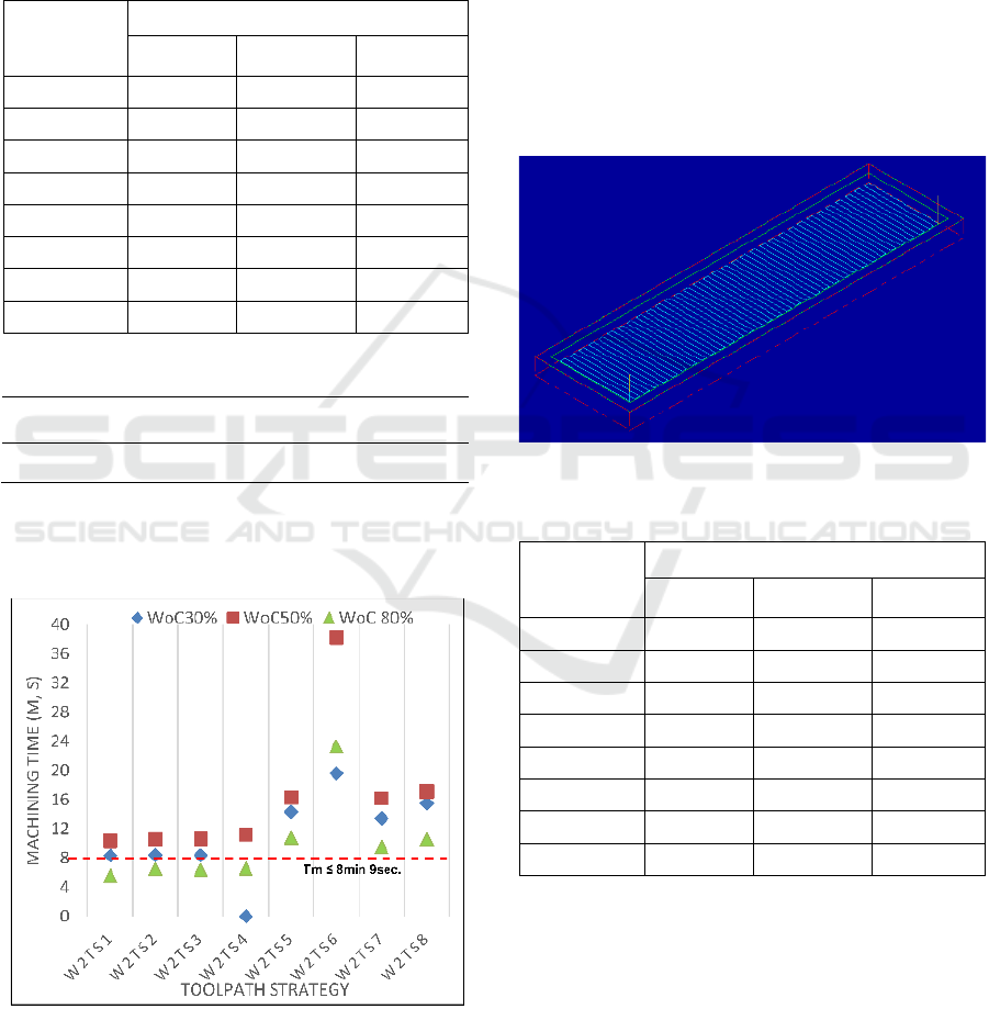
The cross section of the W2 workpiece is a
rectangular with a size of 100 mm x 200 mm as shown
Figure 6. The results of the simulation Machining
Time of the W2 workpiece are shown in Table 6.
Figure 6: Zigzag toolpath on W2 workpiece.
Table 6 shows that the fastest Machining time of
WoC variation and toolpath strategy for cross section
W2 is 80% WoC on TS1 (Zigzag) which has a time
of 5 minutes 55 seconds. The longest Machining time
is WoC 50% on TS6 (high speed) which is 38 minutes
21 seconds.
Optimization of CNC Milling Machining Time through Variation of Machine Parameters and Toolpath Strategy in Various Cross-sectional
Shape on Tool Steels and Die Steels Materials
87
The constraint of machining time optimization on
W2 workpiece is 8 min, 9 sec. The constraint value is
obtained from CNC milling machining time
calculations with size of W2 workpieces is 100 mm
and 200 mm, width of cut 50%, feed rate 361
mm/min, D endmill 12 mm. L is 88 x ((200-12)/6+1)+
188 = 3092 mm.
Table 6: Machining time of W2 workpiece.
Variation
Machining Time (minute, seconds)
WoC 30%
WoC 50%
WoC 80%
W2TS1
8,32
10,31
5,55
W2TS2
8,40
10,52
6,44
W2TS3
8,37
10,56
6,32
W2TS4
9, 2
11,20
6,49
W2TS5
14,30
16,30
10,7
W2TS6
19,58
38,21
23,28
W2TS7
13,44
16,16
9,48
W2TS8
15,47
17,13
10,51
Table 7: Machining time calculation of W1.
Size
L (mm)
A=O
(mm)
Fr
(mm/min)
Tm (min,
sec)
a (mm)
b (mm)
100
100
3092
0
361
8,9
The plot of machine time with the machine
parameters and toolpath variations is shown in Figure
5, and the machine time constraint, Tm ≤ 8min, 9sec.
Figure 7: Plot Machine Time vs toolpath strategy on W2.
Result from optimization of machine time show
machine parameters and toolpath strategies that
produce machine time data less than Tm (≤ 8min
9sec) namely W2TS1 on WoC80%; W2TS2 on
WoC80%; W2TS3 on WoC80%; W2TS4 on
WoC80%. Machine parameters and toolpath
strategies that produce an optimum machine time
(small/fastest) is W2TS1 (zigzag toolpath strategy)
on WoC 80% with time of 5 min, 55 sec.
3.3 Optimization Machining Time of
W3 Workpiece
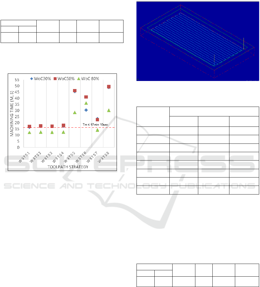
The cross section of the W3 workpiece is a
rectangular with a sizes of 100 mm x 400 mm as
shown Figure 7. The results of the simulation
Machining time of W3 workpiece are shown Table 7.
Figure 7: Zigzag toolpath on W3 workpiece.
Table 7: Machining time of W3 workpiece.
Variation
Machining Time (minute, seconds)
WoC 30%
WoC 50%
WoC 80%
W3TS1
16,50
17,14
12,25
W3TS2
17,24
17,50
12,48
W3TS3
17,19
17,26
12,33
W3TS4
17,42
18,00
12,49
W3TS5
45,51
46,32
28,50
W3TS6
30,45
41,14
36,12
W3TS7
23,28
22,53
14,23
W3TS8
49,02
49,52
30,27
Results of machine times in Table 7 shows that the
fastest Machining time of 80% WoC and TS1
(Zigzag) which has a time of 12 minutes 25 seconds.
The longest Machining time is WoC 50% on TS8
(true spirals) which is 49 minutes 52 seconds
The constraint of machining time optimization on
W3 workpiece is 17 min, 10 sec. The constraint value
is obtained from CNC milling machining time
calculations with size of W2 workpieces is 100 mm
EIC 2018 - The 7th Engineering International Conference (EIC), Engineering International Conference on Education, Concept and
Application on Green Technology
88
and 200 mm, width of cut 50%, feed rate 361
mm/min, D endmill 12 mm. L is 88 x ((400-12)/6+1)+
388 = 6196 mm.
Table 8: Machining time calculation of W3.
Size
L (mm)
A=O
(mm)
Fr
(mm/min)
Tm (min,
sec)
a (mm)
b (mm)
100
100
6196
0
361
17,10
The plot of machine time with the machine para-
meters and toolpath variations is shown in Figure 8,
and the machine time constraint, Tm ≤ 17min, 10sec.
Figure 8: Plot Machine Time vs toolpath strategy on W3.
Result from optimization of machine time show
machine parameters and toolpath strategies that
produce machine time data less than Tm (≤ 17min
10sec) namely W3TS1 on WoC 30% and 80%;
W3TS2 on WoC80%; W3TS3 on WoC80%; W3TS4
on WoC80%; and W3TS7 on WoC80%. Machine
parameters and toolpath strategies that produce an
optimum machine time is W3TS1 (zigzag toolpath
strategy) on WoC 80% with time of 12 min, 25 sec.
3.4 Optimization Machining Time of
W4 Workpiece
The cross section of the W4 workpiece is a
rectangular with a sizes of 200 mm x 100 mm as
shown Figure 9. The results of the simulation
machining time of W4 workpiece shown on Table 9.
Machining time simulation results in the cross
section of the W4 workpiece show that the fastest
Machining time of various WoC and toolpath strategy
variations is 80% WoC on TS1 (Zigzag) which is 5
minutes 18 seconds. The longest Machining time is
50% WoC with TS6 (high speed) which is 27 minutes
38 seconds.
Figure 9: Zigzag toolpath on W4 workpiece.
Table 9: Machining time of W4 workpiece.
Variation
Machining Time (minute, seconds)
WoC 30%
WoC 50%
WoC 80%
W4TS1
08,34
08,48
05,18
W4TS2
08,19
08,58
05,44
W4TS3
08,38
08,54
05,33
W4TS4
09,02
09,18
05,47
W4TS5
14,30
15,00
08,34
W4TS6
18,44
27,38
18,11
W4TS7
10,31
10,20
06,12
W4TS8
15,17
16,06
08,51
The constraint of machining time optimization on
W4 workpiece is 8 min, 34 sec. The constraint value
is obtained from CNC milling machining time
calculations with size of W2 workpieces is 200 mm
and 100 mm, width of cut 50%, feed rate 361
mm/min, D endmill 12 mm. L is 188 x ((100-
12)/6+1)+ 88 = 3096 mm.
Table 10: Machining time calculation of W4.
Size
L (mm)
A=O
(mm)
Fr
(mm/min)
Tm (min,
sec)
a (mm)
b (mm)
100
100
3096
0
361
8,34
The plot of machine time with the machine
parameters and toolpath variations is shown in Figure
8, and the machine time constraint, Tm ≤ 8min, 34sec.
Result from optimization of machine time show
machine parameters and toolpath strategies that
produce machine time data less than Tm (≤ 8min
34sec) namely W4TS1 on WoC 30% and 80%;
W4TS2 on WoC 30% and 80%; W4TS3 on
Optimization of CNC Milling Machining Time through Variation of Machine Parameters and Toolpath Strategy in Various Cross-sectional
Shape on Tool Steels and Die Steels Materials
89
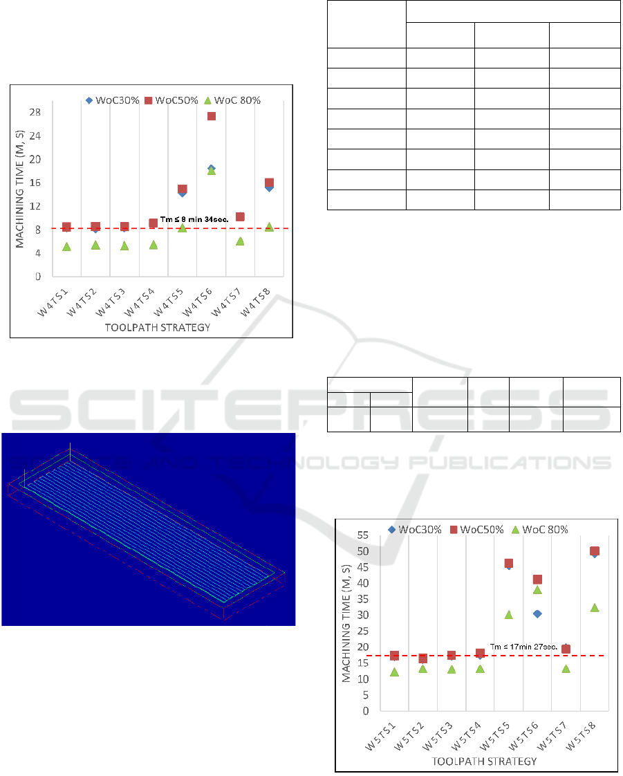
WoC80%; W4TS4 on WoC80%; W4TS5 on
WoC80%; and W4TS7 on WoC80%. Machine
parameters and toolpath strategies that produce an
optimum machine time (small/fastest) is W3TS1
(zigzag toolpath strategy) on WoC 80% with time of
5 min, 18 sec.
Figure 10: Plot Machine Time vs toolpath strategy on W4.
3.5 Optimization Machining Time of
W5 Workpiece
Figure 11: Zigzag toolpath on W5 workpiece.
The cross section of the W5 workpiece is a
rectangular with a sizes of 400 mm x 100 mm as
shown Figure 11. The results of the simulation
Machining time of the W5 workpiece are shown
Table 11.
Machining Time simulation results in the cross
section of the W5 workpiece show that the fastest
Machining Time is 80% WoC and TS1 (Zigzag)
which is 12 minutes 19 seconds. The longest
Machining Time is 50% WoC with TS6 (true spiral)
which is 50 minutes 09 seconds.
Table 11: Machining time of W5 workpiece.
Variation
Machining Time (minute, seconds)
WoC 30%
WoC 50%
WoC 80%
W5TS1
17,15
17,38
12,19
W5TS2
16,24
16,51
13,25
W5TS3
17,23
17,50
13,06
W5TS4
17,46
18,13
13,23
W5TS5
45,53
46,29
30,13
W5TS6
30,44
41,18
38,02
W5TS7
20,04
19,42
13,40
W5TS8
49,24
50,09
32,36
The constraint of machining time optimization on
W5 workpiece is 17 min, 27 sec. The constraint value
is obtained from CNC milling machining time
calculations with size of W2 workpieces is 100 mm
and 200 mm, width of cut 50%, feed rate 361
mm/min, D endmill 12 mm. L is 388 x ((100-
12)/6+1)+ 88 = 6296 mm.
Table 12: Machining time calculation of W5.
Size
L (mm)
A=O
(mm)
Fr
(mm/min)
Tm (min,
sec)
a (mm)
b (mm)
100
100
6296
0
361
17,27
The plot of machine time with the machine
parameters and toolpath variations is shown in Figure
8, and the machine time constraint, Tm ≤ 17min,
27sec.
Figure 12: Plot Machine Time vs toolpath strategy on W5.
Result from optimization of machine time show
machine parameters and toolpath strategies that
EIC 2018 - The 7th Engineering International Conference (EIC), Engineering International Conference on Education, Concept and
Application on Green Technology
90
produce machine time data less than Tm (≤ 17min
27sec) namely W5TS1 on WoC 30% and 80%;
W5TS2 on WoC30%, 50% and 80%; W5TS3 on
WoC30% and 80%; W5TS4 on WoC80%; and
W3TS7 on WoC80%. Machine parameters and
toolpath strategies that produce an optimum machine
time is W3TS1 (zigzag toolpath strategy) on WoC
80% with time of 12 min, 19 sec.
The optimization results in each cross section of
the workpiece (W1-W5) obtained that the fastest
(optimal) machining time is a parameter zigzag
toolpath strategy and width of Cut 80%. The zigzag
toolpath uses the shortest cutting path compared to
other toolpath strategies, while WoC 80% allows
achieving the largest area cuts compared to WoC30%
and 50%. The spindle rate and feed rate are the same
for WoC 50% and 80% This results in 80% smaller
WoC machining time compared to 50%. Using the
same value for speed and feed rate refers to catalog
data from the guhring tool.
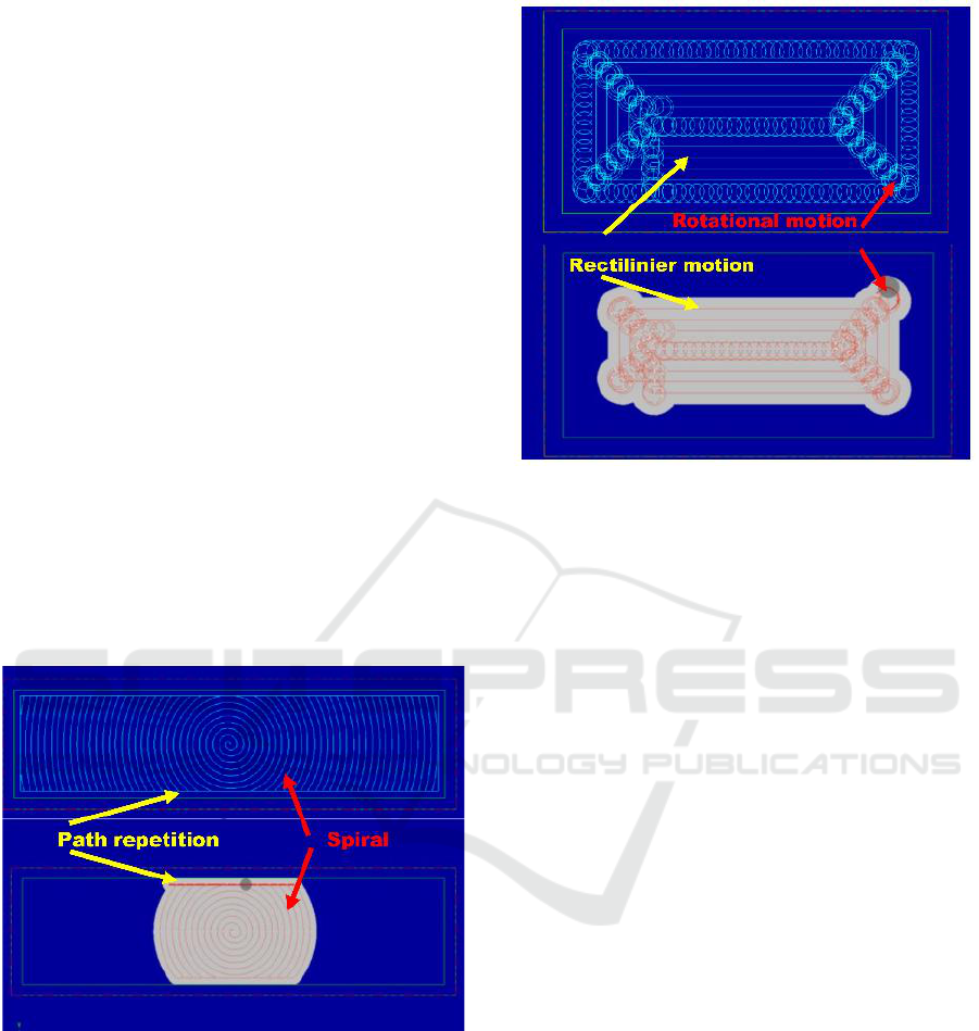
The parallel spiral toolpath produces the second
lowest machining time after zigzag. While the
toolpath with the biggest machining time values is
true spirals and high speed. True spirals toolpath has
the longest cutting path in the form of W3 and W5
resulting in the largest machining time value.
Figure 13: True spirals toolpath on W5 workpieces.
The longest path is generated from repetition of
paths on the X axis for W3 objects and, repetition of
paths on the Y axis for W4 workpiece. W3workpieces
has a longitudinal size on the Y axis, while W5 has a
longitudinal size on the X axis. The occurrence of
path repetition due to the movement of a rotating
cutting device (spiral). True spiral toolpath on W5
workpiece shown on figure 13.
Figure 14: High speed toolpath on W5 workpieces.
The biggest machining time on the workpiece W1,
W2, and W4 is generated from high speed toolpath.
The high speed toolpath uses a rotation and straight
cut path. Rotational movement is a long movement of
the cutting path so as to produce a large machining
time.
4 CONCLUSIONS
The optimal machining time with the lowest / fastest
value in each workpiece cross section is generated
from the zigzag toolpath setting and 80% width of
cut. The optimal value of the fastest machining time
is affected by the length of the planned cutting path.
The Zigzag toolpath has the shortest cutting path
compared to other toolpath strategies. The optimum
machining time value on a square cross section (W1)
is 3 minutes, 11 seconds; W2 is 5 minutes 55 seconds;
W3 is 12 minutes 25 seconds; W4 is 5 minutes 18
seconds; and W5 is 12 minutes 19 seconds. The
greater the width of cut value, the greater the area cut
at one time the movement path.
The toolpath strategy produces the largest values
of machining time is true spirals and high speed. True
spirals toolpath has the longest cutting path on W3
and W5 workpiecs resulting the largest machining
time value. The longest path is generated from
repetition of paths in longitudinal direction of
workpieces. Path repetition occure due to the
movement of a rotating cutting (spiral).
The largest machining time on the W1, W2, and
W4 workpiece is generated from high speed toolpath.
Optimization of CNC Milling Machining Time through Variation of Machine Parameters and Toolpath Strategy in Various Cross-sectional
Shape on Tool Steels and Die Steels Materials
91

Rotational movement on high speed toolpath has a
long movement of the cutting path that produce a
large machining time.
REFERENCES
Akmal, K. Shamsuddin, A. R., Kadir, Ab., Osman, M. H.,
2013. A Comparison of Milling Cutting Path Strategies
for ThinWalled Aluminum Alloys Fabrication. IJES.
Vol. 2 Issue 3 Pages 01-08.
Awale, A. S., Inamdar, K. H., 2015. Review on High Speed
Machining of Hard Material. JETIR Volume 2, Issue 3
pp.517-524.
Daneshmand, S., Abdolhosseini, M. M., Aghanajafi C.,
2011. Investigating the Optimal Tool Path Strategies
Based on Machine time in CAD-CAM. Australian
Journal of Basic and Applied Sciences, 5(12): 2320-
2326.
Daneshmand, S., Mirabdolhosayni, M., Aghanajafi, C.,
2013. Sifting Through the Optimal Strategies of Time-
Based Tools Path Machining in Software CAD-CAM.
Middle-East Journal of Scientific Research 13 (7): 844-
849.
Dimitrov, D., Saxer, M., 2012. Productivity Improvement
in Tooling Manufacture through High Speed 5 Axis
Machining” in Procedia CIRP 1(2012)277 – 282, 5th
CIRP Conference on HPC 2012.
Gavril, M., Andrei, M., Lucian, T., 2016. Increase
Productivity and Cost Optimization in CNC
Manufacturing. IManEE pp1-6
Gologlu, C., Sakarya N., 2008 “The effects of cutter path
strategies on surface roughness of pocket milling of
1.2738 steel based on Taguchi method”. Journal of
Material Processing Technology 206, 7-16.
Guhring., 2015. High-Performance Solid Carbide End Mill
Catalog 3rd Edition. USA. www.guhring.com
Minquiza, G. M., Borjaa, V., Parra, M. L., Alejandro, C.,
Reivicha, R., Domínguezb, M. A., Alejandro., 2014.
586, 6th CIRP International Conference on High
Performance Cutting, HPC 2014.
Prajapati, R., Rajurkar, A., Chaudhary, V., 2013. Tool Path
Optimization of Contouring Operation and Machining
Strategies for Turbo Machinery Blades. IJETT Vol. 4
Issue5.
Saroj, A. K., Jayswal, S. C., 2013. Analysis of Different
Parameters on Tool Path for Machining Sculptured
Surfaces. (IJERT) Vol. 2 Issue 10.
EIC 2018 - The 7th Engineering International Conference (EIC), Engineering International Conference on Education, Concept and
Application on Green Technology
92
