
The Motion Response Analysis of Floating Jack-Up Rigs in the
Operating Condition
Asri Sawiji
Universitas Islam Negeri Sunan Ampel, Jl. A. Yani 117 Surabaya, Indonesia
Keywords: floating jack-up, motion, wave, six degree of freedom
Abstract: Natural gas reservoirs near the seabed (shallow gas) make drilling activities prone to blowout. Using a
modified jack-up in a floating state will facilitate evacuation to avoid gas explosion. The floating jack-up is a
misuse of the concept of jack-up structure design which must be operated in a fixed structural condition. This
issue requires further investigation regarding the feasibility of the drilling operation process. Motion response
of the floating structure is revealed in order to explore the feasibility of the operation of the jack-up. In this
study, the motion response of the floating bodies will be compared by varying the jack-up leg length immersed
in the water. The site reviewed in this analysis is in the Madura Strait, Indonesia. The floating jack-up was
modeled and analysed in the MOSES offshore platform design and simulation software. Results show that
the response amplitude operator of pitch motion has the most significant response in each variation. From
motion validation with rules it can be concluded that the heave motion of this structure exceeded criteria limits
for BOP and riser operations but is allowed for drilling activities. The obtained results show that a drilling
process in the Madura Strait site using a floating jack-up could possibly be operated by lowering the legs
until it reaches five meters above the seabed without running BOP and risers.
1 INTRODUCTION
Jack-up rigs are offshore drilling platforms with legs
that can be raised and lowered in the installation
process. The concept of designing a jack-up structure
is that it combines the advantages of fixed structure
buildings such as platform jacket legs and floating
platforms such as floating barges. The jack-up is a
self-elevating unit. The transportation and installation
phases are done during floating conditions, while the
spud cans will be jacked onto the seabed during the
operating or drilling phase (DNV, 1996).
Seabed sub-surface soil conditions containing
shallow gas where the trap of natural gas reservoirs
located near the seabed floor will cause the area to be
prone to blowout. The presence of shallow gas may
possibly cause blowout that will damage the jack-up
structure. The penetration of jack-up legs will make it
difficult to structure evacuation, because the jacking
process of the jack-up legs will take a long time. This
problem raises an idea: what if this offshore building
structure is operated under conditions where the legs
are not fixed on the sea floor or operated in floating
condition. Jack-up legs do not touch the sea floor,
meaning jack-ups will always be floating in the ocean
so evacuation procedures can run smoothly and
prevent damage to the structure. A jack-up structure
with hanging legs may prove to be the solution. In
accordance to the concept of jack-up design, the
floating structure of the jack-up clearly does not fulfil
the design rule. It may be questioned whether the
jack-up can remain stable in a state of operation
(drilling activities), how the structure moves, if it can
still withstand environmental loads such as wind,
currents and waves. With this analysis, we will find
out whether the floating jack-up can be operated in
drilling or operating conditions.
This research focuses on jack-up rigs of the three
independent leg type with K-braced truss legs. It
discusses how the motion response of the floating
jack-up was subjected to the environmental load. The
location of study of this simulation is in the Madura
Strait in Indonesia, which has a water depth of 57m.
This paper describes and compares the structural
motion analysis of six variations of immersed jack-up
legs which were subjected to environmental loads.
The behavior of motion response of each variation
was recorded.
Sawiji, A.
The Motion Response Analysis of Floating Jack-Up Rigs in the Operating Condition.
DOI: 10.5220/0008908100002481
In Proceedings of the Built Environment, Science and Technology International Conference (BEST ICON 2018), pages 191-196
ISBN: 978-989-758-414-5
Copyright
c
2022 by SCITEPRESS – Science and Technology Publications, Lda. All rights reserved
191
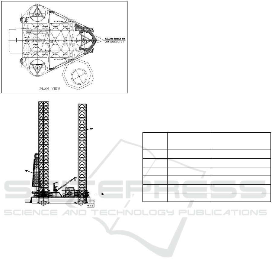
Figure 1: Outboard Profile and Plan Views
The principle particulars of the vessel are as indicated
below:
Length Moulded
64.643 m
Width of Hull
64.008 m
Depth of Hull
7.925 m
Leg length
140.208 m
Overall Length of Spud Legs
140.208 m
Longitudinal Leg Centres
40.915 m
Transverse Leg Centres
47.244 m
LCG Bow (Forward)Leg
10.622 m
Diameter of Spud Cans
7.315 m
Displacement at Load Line
23033.5 kips
The jack-up platform was normally designed to
function in several different operational modes, i.e.
the transit, installation, retrieval and operational
condition. Response of the jack-up in the floating
mode of operation is obviously far different from that
of the jack-up in the installed, elevated condition.
Both of these modes are critical to the safe operating
of a jack-up unit as each mode of operation may
impose its own limiting design criteria on certain
parts of the structure (DNV, 1996). In the
transportation phase, the jack-up is towed towards the
drilling point location with the leg lifted above the
hull. Arriving at the drilling point, the jack-up legs are
lowered down onto the seabed then jacked until the
bearing capacity is sufficient to hold the sea current.
The installation phase is the phase where the jack-up
leg is self-elevating upward and downward in the sea
water, which is commonly called the jacking process.
The operation phase is the phase where the jack-up
performs its function.
This paper considered the operation phase as the
focus of analysis. Six cases were chosen to analyse
the motion response of the jack-up platform to
explore the possibilities of this structure when
operated in a floating condition. The cases are
described in the table below.
Table 1: Motion response analyses of case studies.
Case
Immersed Leg
Length (m)
Remarks
1
0
Towing
2
14.25
¼ of Water Depth
3
28.5
½ of Water Depth
4
42.75
¾ of Water Depth
5
52
5 meters above seabed
6
57
Jacked
2 METHOD
The jack-up rig of this model was simulated on the
MOSES 7.0 software with the aim of discovering the
motion response of the structure. The jack up was
designed in three dimensions and was only
considered on the operating condition. The WSD
method was generally used in this analysis. The hull
and leg structure was modelled as subjected to
horizontal load (wind, wave, current load) for all
cases. The structural load implied on this model is the
self-weight of the jack-up, distributed load on the hull
and the derrick load. The Metocean data used in this
analysis was one year of the return period. Based on
environmental data, the heading direction was
dominantly from the west. The wind speed used in
this analysis was 3 seconds gusting condition or
50.268 knots, the significant wave height was 3.24
meters, with a wave period of 9.01 seconds. The
current speed was 0.62 m/s on the mean sea level and
0.49 m/s on the seabed.
The floating jack-up is identified as a mobile
offshore drilling unit (MODU). The designing of a
BEST ICON 2018 - Built Environment, Science and Technology International Conference 2018
192
MODU needs to consider the variation of
environmental load, minimize riser vibration and
interference between risers and structure in order to
anticipate the structural failure and blow out. To
understand which cases can be applied on the drilling
operation condition based on the analysis of criteria
such as motion response, drilling and tripping,
running and setting casing, running and landing
BOP/Riser, transferring equipment, they were
verified based on the book Floating Drilling:
Equipment and Its Use by Riley Sheffield, 1980.
The motion of floating was considered in order to
find out the behaviour of the structure. The behaviour
of the floating structure is the freedom of movement
or oscillation. This oscillation consists of six
movements, which consist of three lateral movements
and three rotational movements in three direction
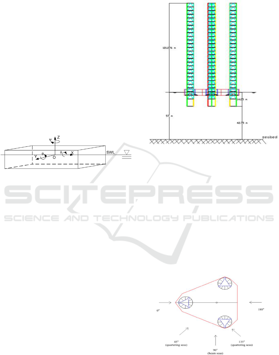
axes, as shown on Figure 2.
Figure 2: Six degrees of freedom
These types of movements are:
a. Surging: Movement of lateral oscillations on the x-
axis.
b. Swaying: Movement of lateral oscillations on the -
y axis.
c. Heaving: Movement of lateral oscillations on the -
z axis.
d. Rolling: Movement of rotational oscillations on the
x-axis.
e. Pitching: Rotational oscillation movement against
the -y axis.
f. Yawing: Rotational oscillation movement against
the -z axis.
However, the scope of work of this paper only
considered the heave, roll and pitch motions. These
three motion responses were analysed on the MOSES
software with the output of Response Amplitude
Operator. The Response Amplitude Operator was
used to assess the frequency-domain linear wave
body response of the floating platform during the
design process. RAO is defined as the response
amplitude per unit wave height (Chakrabarti, 1987).
𝑅𝑒𝑠𝑝𝑜𝑛𝑠𝑒
(
𝜔
)
= 𝑅𝐴𝑂
(𝜔) (1)
Where: = Wave amplitude (m, ft)
Figure 3: Jack-up modelling on MOSES 7.0 (case 2)
3. RESULT AND DISCUSSION
Sawiji (2015) stated that the stability of a floating
jack-up with the leg length of 140.208m and water
depth 57m is classified as a stable structure with an
area ratio above 1.4 and a tilted angle more than
28(American Bureau of Shipping, 2005). In
structure response analysis, cases are exposed to
waves, winds and currents in five different directions,
i.e. in the heading direction of 0°, 45°, 90°, 135°,
180°. In the MOSES software, the angle direction is
read in a clockwise direction. The five heading
directions were the approaching wave and wind
direction.
Figure 4: Heading Direction
The following figure displays some of the results
of the structural response from several cases. The
chart shows that the heave motion at heading 90 was
The Motion Response Analysis of Floating Jack-Up Rigs in the Operating Condition
193
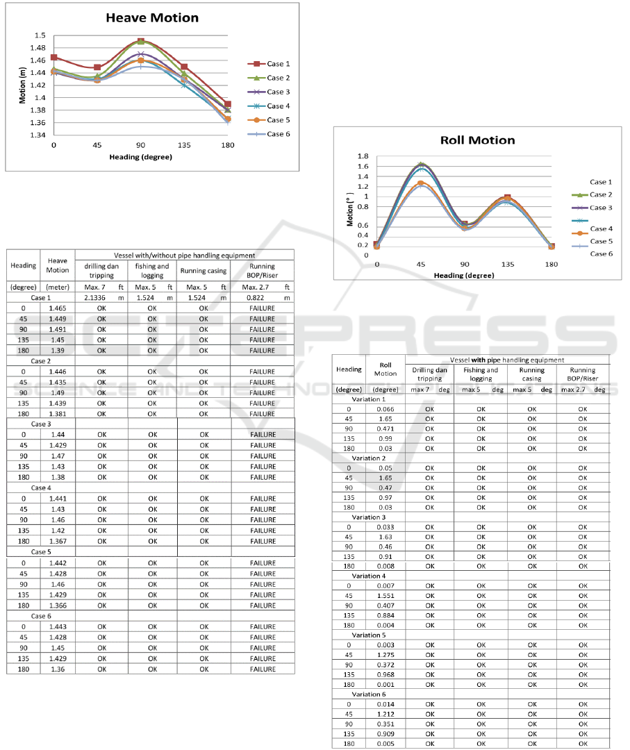
relatively higher than the other heading directions in
all cases. The maximum heave motion in these cases
was 1.491m on 90° direction on case 1. Based on
(Sheffield, 1980), the heave RAO should be under 10
ft or 3.048 m. It shows that the vertical oscillation for
the six cases has fulfilled the criteria.
Figure 5: Heave motion of six cases
Table 2: The results of heave motion by considering
the floating jack-up as a vessel with/without pipe
handling equipment.
After considering the response amplitude operator
as a criteria of mobile offshore drilling unit operation,
it should also be reviewed and simulated when all
activities are running. To determine whether it fulfils
the drilling criteria, as mentioned in the book Floating
Drilling: equipment and its use, Sheffield 1980,
where the heaving movement limit criteria for drilling
and tripping activity must be below 7 ft, in this study
it can be concluded that all activities can still run,
except the activity of running BOP and installation of
risers. The running of the blow out preventer requires
the maximum allowable heaving motion of 0.822m,
whereas the result measured out of the criteria.
Different to the heave motion, the roll motion
graphs show that the structural movements tend to be
high in the direction of loading 45° and 135°, and tend
to be low in headings 0°, 90 ° and 180 °. The highest
motion roll was 1.65, heading 45°, on case variation
one.
Figure 6: Roll motion of six cases
Table 3: The results of roll motion by considering the
floating jack-up as a vessel with pipe handling
equipment
BEST ICON 2018 - Built Environment, Science and Technology International Conference 2018
194
As for roll motion, the maximum allowable roll
motion was 7 degrees. The rolling movements that
occurred in the structure were feasible for drilling
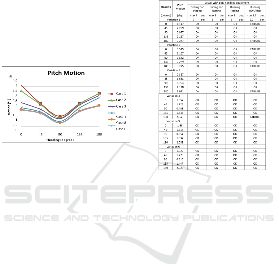
activities for all cases. Moreover, from the Pitch
Motion graphs we can see that the pitching motion of
the structure is very high in headings 0° and 180°,
with the maximum value of 4.117 degrees in the first
variation in heading 0°.
Figure 7: Pitch motion of six cases
Regarding pitch motion, the maximum
allowable pitch movement for drilling and tripping
activities is 7 degrees. In the case of pitch motion, the
running BOP and riser installation activities in cases
5 and 6 were accepted.
Table 4. The results of pitch motion considering the
floating jack-up as a vessel with pipe handling
equipment
4 CONCLUSION
The results show that the response amplitude operator
of pitch motion had the most significant response in
each variation. From the motion validation with rules,
it can be concluded that the heave motion of this
structure exceeded criteria limits for BOP and riser
operations, but is still allowed for drilling activities.
The obtained results show that drilling processes in
the Madura Strait site using the floating jack-up could
possibly be operated by at least lowering the legs until
it is 5 meters above the seabed without running BOP
and risers.
REFERENCES
American Bureau of Shipping. 2005. Commentary on
the ABS Rules for Building and Classing
Mobile Offshore Drilling Units, 2001 Part 3-
Hull Construction & Equipment, January, 53.
Chakrabarti, S. K. ed 1987. Fluid Structure
Interaction in Offshore Engineering,
Southampton: Computational Me-chanics
Publications.
DNV. 1996. Guidelines for Offshore Structural
Reliability - Application to Jackup Structures.
The Motion Response Analysis of Floating Jack-Up Rigs in the Operating Condition
195

Sawiji, A. 2015. Analisis Stabilitas Jack-Up
Terapung pada Kondisi Operasi di Selat
Madura. Marjan, 0101, 37–41.
Sheffield, Riley. 1980. Floating Drilling: Equipment
and its Use.Practical Drilling Technology,
Vol.2, Gulf Publishing Company, Houston,
TX,.
BEST ICON 2018 - Built Environment, Science and Technology International Conference 2018
196
