
Neural Network Harmonic Filter for Microgrid System
Mat Syai’in
1
, Dedy Kurniawan Setiawan
2
, Agus Muhammad Hatta
3
, Yuniar Farida
4
1
Shipbuilding Institute of Polytechnic Surabaya (SHIPS/PPNS), Surabaya Indonesia
2
University of Jember, Jember Indonesia
3
Institut Teknologi Sepuluh November (ITS), Surabaya Indonesia
4
State Islamic University Sunan Ampel, Surabaya Indonesia
Keywords: Active Filter, Neural Network, Total Harmonic Distortion, Microgrid
Abstract: Development of electrical technology, especially converters technology, has made significant change inthe
characteristics of electrical power systems. Moreover, the need of converting electrical signal from pure sine
to distorted sine from renewable energy based generators makes the use of converter technology increase.
Currently, the use of renewable energy based power plants together with traditional generators has become
commonplace, commonly known as microgrid systems. This is intended to improve efficiency, reduce
environmental pollution, and preserve nature. Microgrid systems have a very positive impact on the electric
power system. However, microgrids also cause negative impacts such as harmonics. This research is
developing active filter based on Neural Network concept. Neural Network is used as control strategies to
produce signals opposite harmonic signals. The simulation results show that the active filter based on neural
network can reduce the Total Harmonic Distortion (THD) in microgrid systems effectively.
1 INTRODUCTION
Development of electrical technology makes
significant changes in the characteristics of electrical
power systems. This is due to the dominance of the
use of digital technology in each sector. Digital
technology, especially converter technology, has
changed the nature of the electrical signal from pure
sine to distorted sine (Chakir, Kamwa et al. 2014;
Anwar, Elrayyah et al. 2015; Hashempour, Savaghebi
et al. 2016; Gonzatti, Ferreira et al. 2017). The more
affordability of renewable energy based generators
makes the use of converter technology increase.
Currently, the use of renewable energy based
power plants together with traditional generators has
become commonplace, commonly known as
microgrid systems (Abdelsalam, Massoud et al. 2011;
Li, Li et al. 2016; Cao, Zhang et al. 2018; Feng, Zeng
et al. 2018). This is intended to improve efficiency,
reduce environmental pollution, and preserve nature
(Dudurych, Rogers et al. 2012). Microgrid systems
have a very positive impact on the electric power
system. However, microgrids also cause negative
impacts such as harmonics. Harmonics can be
systemically detrimental if it is not well controlled
(Setiawan et al. 2015).
Regarding to minimizing the negative effects of
harmonics, many researchers have developed filter
technology, both passive filters and active filters.
Active and passive filters have their own advantages
and disadvantages. One of the advantages of passive
filters is relatively cheaper price, but passive filter
applications only work effectively under relatively
constant loading conditions, which are common in
industrial areas. As for the active filter, the price is
quite expensive, but it can be applied to various
loading patterns.
This research developed an active filter by
employing abc-dq transformation. The advantage of
using dq frame is the signal will be easier to control
because the value in dq frame is not influenced by
time, which is very different from value in abc frame
that changes by the time.
In this paper, Neural Network (NN) control was
examined to replace the PI controller for controlling
the active power filter. Simulation was performed in
MATLAB after training the neural network
(supervised learning) and it is shown that results are
acceptable and applicable in grid system. Compared
to PI controller, the NN controller can be less
complicated and less costly to implement in industrial
control applications (Setiawan et al. 2009).
344
Syai’in, M., Setiawan, D., Hatta, A. and Farida, Y.
Neural Network Harmonic Filter for Microgrid System.
DOI: 10.5220/0008906000002481
In Proceedings of the Built Environment, Science and Technology International Conference (BEST ICON 2018), pages 344-349
ISBN: 978-989-758-414-5
Copyright
c
2022 by SCITEPRESS – Science and Technology Publications, Lda. All rights reserved
2 LITERATURE REVIEW
2.1 Modeling of Microgrid Systems
Microgrid systems in this paper are operated stand
alone, with three components of power plant. The
first is conventional power plant (diesel power plant),
the second is direct photovoltaic (PV) systems, and
the third is PV systems with battery.
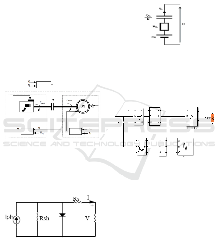
2.1.2 Diesel Power Plant Model
Diesel power plant (DPP) model is generally
constructed by a diesel engine and synchronous
generator (SG). The complete dynamic model of DPP
requires modelling diesel engine with speed control
and SG with the system voltage control as well as
clutch between the SG and diesel engine as shown in
(Fig.1) [15-16].
Voltage
Regulator
Speed
Regulator
Diesel Motor Synchronous Generator
Controller
Figure 1: DPP model
2.1.2 Photovoltaic Systems Model
The electrical power generated and terminal voltage
of Photo Voltaic (PV) module depend on solar
radiation and ambient temperature. The equivalent
electrical circuit describing the solar cells array used
in the analysis is shown in (Fig.2).
Figure 2: PV equivalent circuit
2.1.3 Modeling of Battery Storage System
In this work, it was developed a model of the Ni-MH
electrochemical battery. The equivalent circuit of the
battery storage system is presented as in (Fig.3) [19]:
Figure 3: Electrical equivalent model of the battery
The simulation of this paper is aimed to show the
effectiveness of proposed method to reduce total
harmonic distortion (THD) referring to IEEE 519-
2014. The harmonics source simulated in this paper
was harmonics that were produced by rectifier. The
rectifier model can be explain as follows:
Figure 4: Load model
In this simulation, there were two kinds of load
model. The first model is linear load containing R, L
and C. The second model is non-linear load
containing power converters.
2.2 Modeling of Harmonic Filter
Filter used in this simulation is harmonic active filter.
There are two types of harmonic filter modeling. The
first one is harmonic filter modeling based on
Proportional Integral (PI) control. This type was used
as comparison method to verify proposed method
performance. The second modelling is harmonic filter
based on Neural Network (NN). This type is proposed
method.
Neural Network Harmonic Filter for Microgrid System
345
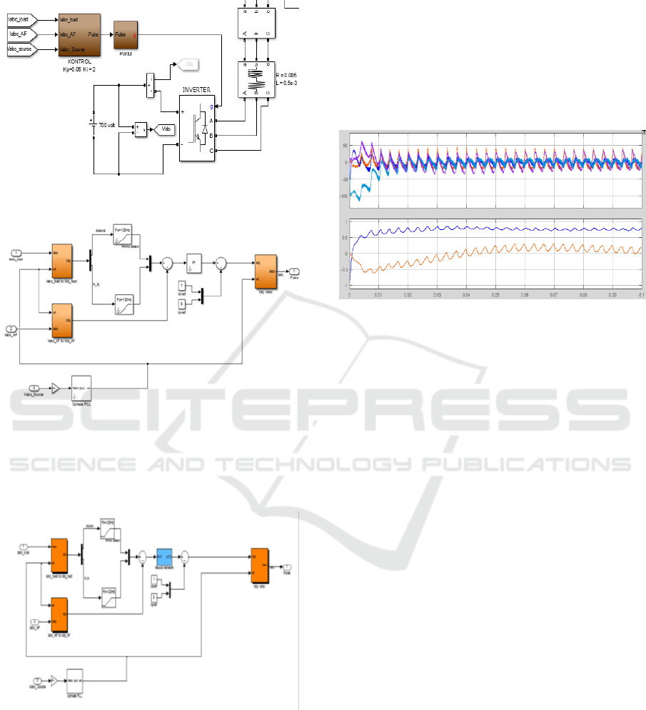
2.2.1 Harmonic filter based on PI controller
Figure 5: Model of Active Harmonic Filter
Figure 6: Model of Proportional Integral (PI)
controller for Active Harmonic Filter
2.2.2 Harmonic Filter Based on Neural
Network
Figure 7: Model of Neural Network (NN) Controller
for Active Harmonic Filter
2.3 Neural Network Training Process
Structure of Neural Network used in this simulation
has four inputs and two outputs. The inputs are load
voltages/currents in d-q frame and APF (active power
filter) voltages/currents in d-q frame. NN is
employing single hidden layer with 7 neurons for
modelling control strategy. Sigmoid function is used
as activation function. Sample data used as training
data is given in (Fig.8).
Figure 8: one of some pattern of training data
For convenience of data presentation, the data
training is provided in the graph to reduce number of
table rows due to the huge numbers of training data.
The upper box graph of Fig.9 is the input data and the
lower box graph of Fig.9 is the output. The
verification performance of proposed method is
conducted in the next section.
3 RESEARCH METHODS
This paper is aimed to simulate the reduction of THD
(total harmonics distortion) in Microgrid systems
using active filter that was designed in dq frame and
controlled using NN (Neural Network). The NN
controller that was designed in this paper had 4 inputs
and 2 outputs. The inputs were load signals in dq
frame and APF (active power filter) signal in dq
frame. The output was the controlled signals
representing source signals. This signal was drived to
pure signals. The complete design of simulation,
including power generation model, load model, and
filter model, is expresed in the flowchart at (Fig.9).
BEST ICON 2018 - Built Environment, Science and Technology International Conference 2018
346
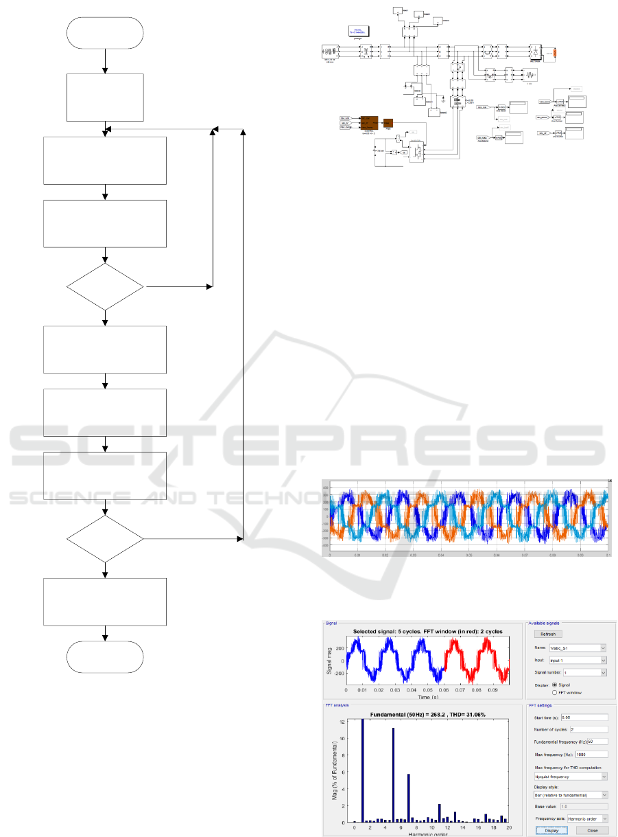
START
Microgrid data
preparation
Modeling of Microgrid
component including
generator, load and filter
Simulation macrogrid system
with filter based on PI
controller
THD is within
the limit?
Taking the NN data training
Training process to get
Structure NN weight that use
as Filter Controller
Testing performance of NN
active filter for several cases
All THD is
within the limit?
Implementation in the Real
Microgrid Systems
STOP
Figure 9: Research Flow Chart
Several procedures simulated in this chapter are
aimed to verify the performance of active harmonic
filter based on Neural Network (NN). The
microgrid system used in this simulation is operated
stand alone (off grid) . The microgrid power plant is
combination of diesel power plant , PV and PV plus
battery. All the load models used in this simulation
were rectifier. Microgrid model used for simulation
is described in (Fig.10).
Figure 10: Model of Microgrid System
4 RESULTS AND DISCUSSION
There were two kinds of signal that were evaluated in
this simulation. The first was voltage signal and the
second was current signal.
4.1 Voltage signals simulation
The original signal voltage before control strategic
was applied. is shown in (Fig.11).
In this step, the load is modelling for producing high
level of Total Harmonic Distortion (THD). From
(Fig.11), it can be seen that the THD level was
31.06%. This simulation is aimed to reduce the THD
using PI controller in comparison to NN controller.
Figure 11a: The current signals before control action
is implemented.
Figure 11b: The THD current before control action is
implemented.
Neural Network Harmonic Filter for Microgrid System
347
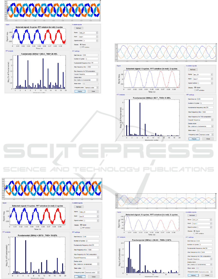
Figure 12: Voltage signals resulted by PI controller.
The signals voltages in (Fig.11) were controlled
using PI controller. The model of PI controller can be
seen in (Fig.7). The result is provided in (Fig.12).
From the figure, it can be seen that the THD was
decreased from 31.06% to 20.16%. The THD level in
this case was still far from the IEEE 519 standard, but
from the result, it can be concluded that the PI
controller can reduce the THD to 33.16%.
The next simulation was controlling voltage
signals in (Fig.11) using NN controller. NN controller
model can be seen in Fig.8 and the result can be seen
in (Fig.13).
Figure 13: Voltage signals resulted by NN controller.
From the Figure, it can be seen that the THD
decreased to 19.62 %. This result has shown that
using NN controller can reduce THD better than by
using PI controller. By using NN controller, it can
reduce THD to 34.95 %. So, it can be concluded that
in this case, NN controller is better than PI controller.
4.2 Current Signals Simulation
Figure 14: The current signals before treated by
controller.
The current signals used as signals test in this
simulation can be seen in the (Fig.14). From the
figure, it can be seen that the signal had THD 5.38 %.
This signal was little bit over IEEE 519 standard. The
signal was then treated using PI controller. The signal
resulted by PI controller can be seen in the (Fig.15).
Figure 15: Current signals resulted by PI controller.
BEST ICON 2018 - Built Environment, Science and Technology International Conference 2018
348
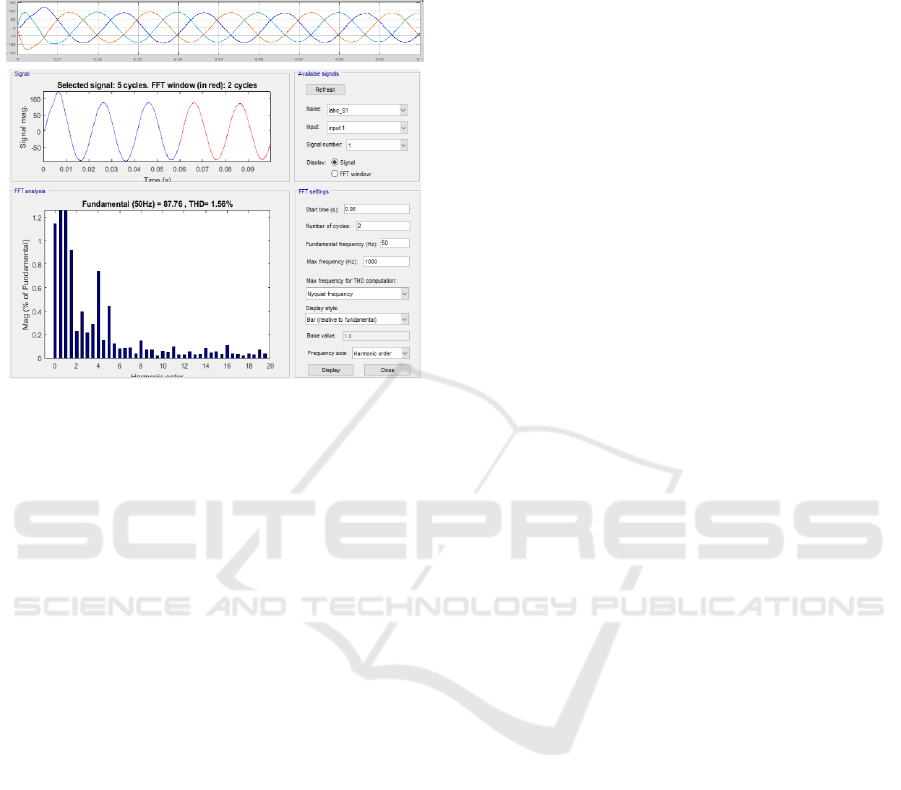
Figure 15 gives information that THD current
decreased from 5.38% to 2.92 %. According to the
IEEE 519 standard, this signal was within the
standard.
Figure 16: The current signals resulted by NN
controller.
The current signals in Fig.14 were also controlled
by NN controller and the results can be seen in the
(Fig.16). From the figure, it can be seen that the THD
current decreased to 1.56 %. This simulation has also
proved that the NN controller gives better
performance than PI controller does. In this case, the
PI controller can decrease signal by 45.72 % while
NN controller can decrease THD level by 71%.
5 CONCLUSION
From the simulation results provided in section 3,
it can be concluded that the proposed methods, abc-
dq frame transformation and NN controller of Active
Harmonic Filter, have better performance in
comparison to PI controller of active Harmonic
Filter. In the voltage cases, the PI controller can
reduce THD by 33.16 % while NN controller can
reduce by 34.95 %. In other hand, in the current cases,
the PI controller can reduce THD current by 45.72%,
while the NN controller can reduce by 71%.
According to these data, the proposed method is
recomended as method for reducing THD, either
THD voltage or THD current.
REFERENCES
Abdelsalam, A. K., A. M. Massoud, et al. (2011).
"High-Performance Adaptive Perturb and
Observe MPPT Technique for Photovoltaic-
Based Microgrids." IEEE Transactions on
Power Electronics26(4): 1010-1021.
Anwar, S., A. Elrayyah, et al. (2015). "Efficient
Single-Phase Harmonics Elimination Method
for Microgrid Operations." IEEE Transactions
on Industry Applications51(4): 3394-3403.
Cao, X., J. Zhang, et al. (2018). "Joint Energy
Procurement and Demand Response Towards
Optimal Deployment of Renewables." IEEE
Journal of Selected Topics in Signal
Processing12(4): 657-672.
Chakir, M., I. Kamwa, et al. (2014). "Extended
C37.118.1 PMU Algorithms for Joint Tracking
of Fundamental and Harmonic Phasors in
Stressed Power Systems and Microgrids." IEEE
Transactions on Power Delivery29(3): 1465-
1480.
Dudurych, I. M., A. Rogers, et al. (2012). "Safety in
Numbers: Online Security Analysis of Power
Grids with High Wind Pentration." IEEE Power
and Energy Magazine10(2): 62-70.
Feng, J., B. Zeng, et al. (2018). "Evaluating Demand
Response Impacts on Capacity Credit of
Renewable Distributed Generation in Smart
Distribution Systems." IEEE Access6: 14307-
14317.
Gonzatti, R. B., S. C. Ferreira, et al. (2017). "Using
Smart Impedance to Transform High Impedance
Microgrid in a Quasi-Infinite Busbar." IEEE
Transactions on Smart Grid8(1): 428-436.
Hashempour, M. M., M. Savaghebi, et al. (2016). "A
Control Architecture to Coordinate Distributed
Generators and Active Power Filters Coexisting
in a Microgrid." IEEE Transactions on Smart
Grid7(5): 2325-2336.
Li, J., F. Li, et al. (2016). "S-shaped droop control
method with secondary frequency
characteristics for inverters in microgrid." IET
Generation, Transmission &
Distribution10(13): 3385-3392.
Setiawan, DK., M. Ashari, MH. Purnomo (2009),
"Diagonal Recurrent Neural Network Control of
Four-Leg Inverter for Hybrid Power System
Under Fluctuating Unbalanced Loads", Third
International Student Conference on Advanced
Science and Technology (ICAST)Seoul, Korea
Setiawan, DK., Y Megantara, BN Syah (2015),
"Three phase inverter of UPS control system for
harmonic compensator and power factor
correction using modified synchronous
reference frame" Electronics Symposium (IES)
PENS Surabaya, Indonesia
Neural Network Harmonic Filter for Microgrid System
349
