
Evaluation Susceptibility of Equipment against Voltage Sags:
Lamp, Contactor and Variable Speed Drive
Surya Hardi
1
, R. Harahap
1
, S. Achmad
1
and Rohana
2
1
Department of Electrical Engineering, Universitas Sumatera Utara, Medan, Indonesia
2
Department of Eletrical Engineering,University of Muhammadyah Sumatera Utara, Medan, Indonesia
Keywords: Equipment testing, voltage sags, susceptibility standard curve.
Abstract: Information about susceptibility of equipment against voltage sags is important in order to avoid system
production drop out. Recently many electrical equipment are develop by using electronic components for
energy saving. The electronic components have been recognizing as susceptible against voltage sags. This
paper presents test results of susceptible equipments to voltage sags which are fluorescent and mercury
vapor lamps, contactors and variable speed drives. A Schaffner Proffline 2100 electromagnetic
compatibility (EMC) has been used to create voltage sag characteristics. Magnitude and duration are
considered as main characteristics for testing. Point on wave of sag initiation was considered for testing
contactor only. Therefore VSDs are three phase, they were test againt voltage sag types I, II and III. The test
results were evaluated by comparing with sensitivty of standard curve availablesuch as ITIC, SEMI F47 and
immunity curves recommended by IEEE P1668
TM
2014.
1 INTRODUCTION
Voltage sags are one of power quality problems,
which are interesting in power system. They can
cause a serious effect on the equipment performance
degradation. When the equipment is supplied by
voltage sags may result in disruption, malfunction,
tripping undesired and even damage. Finally,
apparent economic losses can occurred on
consumers. Susceptibility of equipment is depending
on voltage sag qualities and equipment types.
Magnitude and duration of voltage sags are main
characteristics and other characteristics are
symmetrical and unsymmetrical of voltage sags,
phase shift angle, point on wave (POW) of sag
initiation, etc. Voltage sags are resultedfrom short
circuit faults in power system and others are large
motor starting and transformer energizing.
There are some ways to asses susceptibility of
equipment against voltage variation among others is
mentioned power acceptability curve designed by
CBEMA viz. computer business equipment
manufacturers association in (Heydt et al. 2001). But
available specifically for voltage sags is
Semiconductor equipment and material institute
(SEMI-F47).Last is standard curve
recommendedby(IEEE P1668
TM
, 2014). The
standards are a method to evaluate ride through of
equipment to voltage sags, whichdistinguishfor one
phase load and three-phase load. Availability
susceptibility curve of equipment individually
become crucial. Because from the curve can be
known ride through of equipment when voltage sag
occurs whether the equipment in operation and
malfunction/trip region. These information can be
get from manufacturer, but it is infrequently or by
other way via laboratory testing. This paper is to
evaluate testing results of equipment sample such as
lamps, contactors and variable speed drives (VSDs).
Those equipment are legitimated as susceptible
against voltage sags. Results obtained were
constructed in a susceptibility curve and then
compared with susceptibility standard curve.
2 STANDARD CURVES RELATED
TO EQUIPMENT
SUSCEPTIBILITY
The CBEMA is earlier standard is named power
acceptability curve was introduced in 1980. The
curve is has become standard guidance within
Hardi, S., Harahap, R., Achmad, S. and Rohana, .
Evaluation Susceptibility of Equipment against Voltage Sags: Lamp, Contactor and Variable Speed Drive.
DOI: 10.5220/0008886800730078
In Proceedings of the 7th International Conference on Multidisciplinary Research (ICMR 2018) - , pages 73-78
ISBN: 978-989-758-437-4
Copyright
c
2020 by SCITEPRESS – Science and Technology Publications, Lda. All rights reserved
73
industry to asses susceptability of automatic data
processing to voltage change in short duration
(Heydt et al. 2001). But it has been applied in many
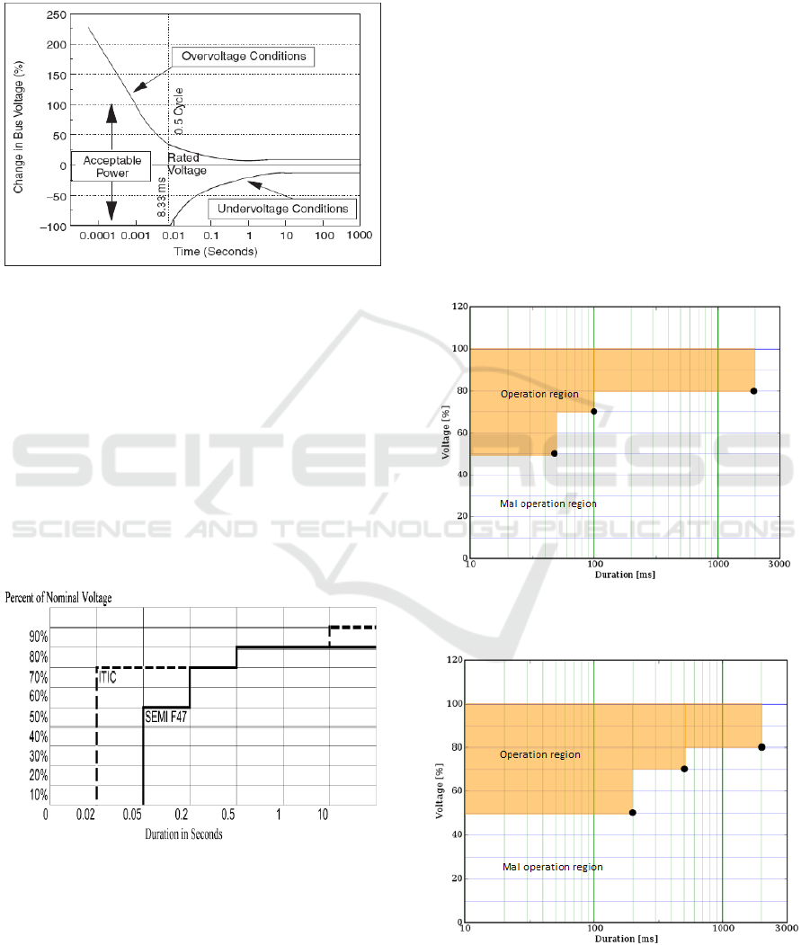
equipment. The curve is dispalyed in Figure 1.
Figure 1:ITIC curve.
This curve explains equipment susceptibility
against voltage variation significantly is influenced
by sag magnitude and duration.
In 1996, CBEMA curve was redesigned and was
called (ITIC), information technology industry
council curve is documented in (IEEE Std. 1346,
1998). This curve is almost similar with old
CBEMA and the different is more piecewise so that
easy to digitize. SEMI F47 is the first time
recommends susceptibility curve specific to voltage
sag (SEMI F47). ITIC and SEMIF47curves are
plotted simultaneously such as in Figure 2.
Figure 2: SEMI F47 and ITIC curves.
It can be seen that the duration of dip is less than
0.2 seconds, the SEMI curve is under ITIC curve
and it is stricter than ITIC. Several equipments pass
the ITIC requirement but not pass for the SEMI F47
requirement curve border.
From Figure2, it can be seen that ITIC has four
knee points which are (75%; 20 ms), (75%; 50ms)
and (80%;50ms), (80%, 100ms) and whereas SEMI
F47 has five knee points which are (50%;50ms),
(50%; 200ms) and (75%;200ms), (75%; 200ms),
(75%; 500ms). Those curves can be used for three
phase and single phase equipment without
distinguish. Generic shape of SEMI F47 has been
applied by some researchers to asses susceptibility
of adjustable speed drive among of found in (Hardi
Surya et al. 2013 and
DjokicS. Z et al. 2005).
IEEE P1668
TM
2014 recommended immunity
test for three phase equipment categorized as type I,
type II and type III. These categorizes base on
amount of phase voltage dropping. Susceptibility
curves are shown in Figure 3 and Figure 4. Those
can be seen that the curves are more simple
compared with earlier curve because they have three
knee points respectively.
Figure 3:Susceptibility standard curve for voltage sagtype
I and type II.
Figure 4:Susceptibility standard curve for voltage sags
type III.
ICMR 2018 - International Conference on Multidisciplinary Research
74
3 FACILITY AND EQUIPMENT
TESTED
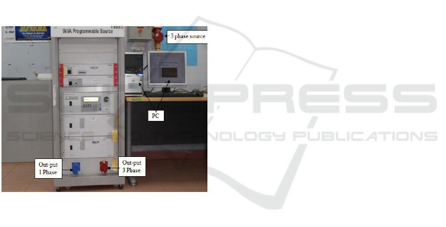
3.1 Facility
Schaffner Proffline 2100 electromagnetic
compatibility (EMC) is equipment capable for
generating the waveform required. It has 3x3kVA
power rating atvoltage magnitude in ranges 0-
300Vrms/phase. The equipment can produce kind
of power quality problems and one of them is as
voltage sag generator (VSG). Voltage sag
chracteristic is set via personal computer (PC).
There are two types out put available of the
equipment i.e. single phase and three phase. Photo of
the equipment tester is shown in Figure 5. This
equipment available at laboratory in Universiti
Malaysia Perlis (UniMAP) and has been used for
testing of equipmentsusceptibility.
Figure 5: Photograph of Schaffner 2100 EMC.
3.2 Equipment Tested
There are three sensitive equipment tested against
voltage sag i.e. lamps, contactors and VSDs.
3.2.1 Lamps
In general the lamps can be extinguished when
supplied with voltage sag, except incandescent lamp.
Both types of lamps such as fluorescent (FCL) lamp
with electronic ballast and mercury vapor lamp
many are widely used people with efficiency reason.
Electronic ballast uses a switch-mode power
supply to modify the input fundamental frequency
voltage to a much higher frequency voltage typically
in the range of 25 to 40 kHz.
The mercury vapor lamp (MVL) is a high
intensity discharge lamp. It uses an arc through
mercury vaporization in a high pressure tube to
generate greatly light bright which is obtained
straight from it is own arc. The lamps need high
voltage at first start. They also are developed from
electronic components therefore susceptible against
voltage sags.
3.2.2 Contactors
AC contactor is an electromagnetic device that acts
when the electromagnetic coil is connected to a
voltage source. Current will flow through the coil
induces a magnetic field consequnce spring attract
for closingits contacts. Magnetic force produced is
influenced by the voltage magnitude. When the
supply voltage is decreased or interrupted, the
springposition is back to initial position so the
contact keeps in open position. Contactors take large
current starting instants to close it contact is
compared with small current in operation condition.
Contactors are recognized also as susceptible
against voltage sags. Motor get energy supply form
utility via contactor. When contactor is subjected
voltage sags, it may trip so that connection between
motor and contactor disconnected.
3.2.3 Variable Speed Drives
Variable speed drives (VSDs) is many found
industrial sectors for controlling speed of an electric
motor. Rotational speed variation of the motor is not
expected, particularly in industry process. Because
can cause damage in end product. VSD is fabricated
from electronic components consequently it is
susceptible toward voltage sag (Petronijevic et al.
2010). It can trip if is supplied by certain low
voltage level in fixed sag duration. Specs ofthe
equipment tested are summarized as in Table 1.
Evaluation Susceptibility of Equipment against Voltage Sags: Lamp, Contactor and Variable Speed Drive
75
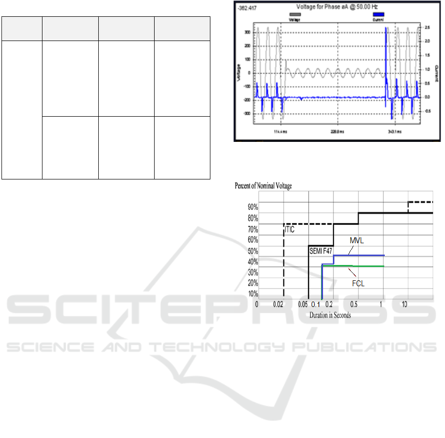
Table 1:Specs of the equipment tested.
Type Lamp Contactor VSD
Rated
FCL with
Ballast
electronic
240V AC,
36W
C(1)
240V, 20A
VSD (1)
3 phase,
0.5 HP,
380-450V,
400Hz.
Mercury
vapor lamp
240V AC
250W
C(2)
240V, 20A
VSD (2)
3 phase
1.5kW,
380- 450 V,
500Hz
3.2.4 Testing Procedure
The equipment was connected to VSG for genera-
ting voltage sags. Out-put voltage of VSG was set
from 90% up down 0% of nominal voltage with step
2.5%. Sag duration of 10ms was progressively
increased until the equipment trip/switch off. If the
equipment is not trip, proceeds for another voltage
sag level, record the equipment trip or not. The
lamps take into account sag magnitude and duration
only, because POW is not influenced on the Lamp.
But the POWof sag initiation was considered in
contactor testing. Because the VDF is three phase, it
was tested for voltage sags types I, II and III such as
recommended.
4 RESULT AND DISCUSSION
Magnitude and duration of voltage sags are main
characteristics used for testing of three types of
equipment namely; lamps, contactors and variable
speed drives.
4.1 Lamp Testing
Two types of lamps were used for testing viz.
Fluorescent lamp (FCL) and Mercury vapor
lamp(MVL).Waveform example of voltage supplied
and current drawn by FCL lamp is shown in Figure
6. This Figure shows the lamp was supplied by
voltage sag of 20% and 200ms in duration which it
in tripping condition. It can be seen during sag, the
current is zero and while end of the voltage sag, the
current extremely increased.
Figure 6: Voltage and current waveform for sag of 20%
and 200ms in duration.
Figure 7:Susceptibility curves for MVL and FCL lamps.
Susceptibilties of the lamps is shown in Figure 7.
MVL lamp is more sensitive than FCL lamp and it
trips is starting at voltage level 40% whereas FCL
sensitive voltage level at 30%. Even so the lamps
meet standard required because they curve lines are
far below standard curves.
4.2 Contactors Testing
Two contactors from distinct manufacturer, which
have same rated, were used in the testing. The
voltage and current waveform when the contactor
C1 subjected to voltage sag of 40% in 100ms
duration. Figure 8 shows the contactor is tripping
condition. Earlier study considered other
characteristics of voltage sag such as POW of sag
initiation was studied by (Jeong et al.2007) in
simulation model and(S. Hardi and I. Daut, 2010) in
experimental test. In this paper the POW considered
from 0
o
until 90
o
in step 15
o
. The most sensitive test
results only are displayed in this paper which the
contactors was supplied by voltage sags with 60
o
POW. The curves resulted such as in Figure 9.
ICMR 2018 - International Conference on Multidisciplinary Research
76
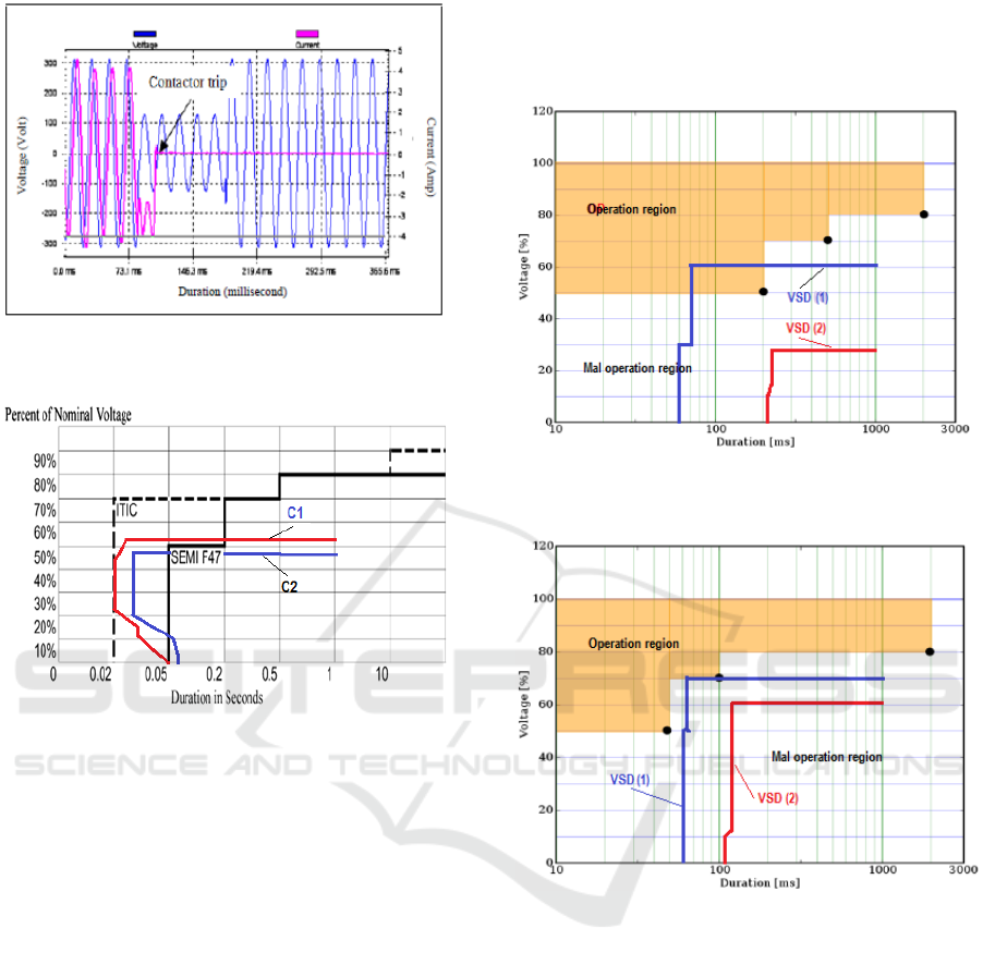
Figure 8: Voltage sag of 40% and current waveform
throughcontactorC1.
Figure 9: Susceptibility curve for contactor C1 and C2.
From Figure 9, it can be seen that there are some
testing points from 20ms to 50ms are above curve
line of SEMI F47. It means the contactors are not
meeting the standard curve but pass for ITIC
standard. For other POWs, the contactors are
satisfying curve standards. The result is not
prensented in this paper. Contactor C1 begins to trip
at voltage level 52.5% and below for duration
around 30ms. Contactor C2 less sensitive compared
with contactor C1. It starts to trip at voltage level
47.5% and duration of 30ms above.
4.3 Variable Speed Drives Testing
Three phase VSDs of distinct rated power and
distinct brand were used for testing against voltage
sag types I, II and III. Difference these types are
based on number of phases dropping and phase
angle shift. Voltage sag type I, only single phase the
voltage drops and voltage sag type II, two phases
voltage drop and phase shift occured. Voltage sag
type III, third phase voltage drop and there is no
phase shift. Test results of VSD subjected to voltage
sags are shown in Figure 10 and Figure 11. Voltage
sag type I did not cause VSD trip hence
susceptibility curve is not presented.
Figure 10:Susceptibility curve of VSDs caused by voltage
sag type II.
Figure 11. Susceptibility curve of VSDs caused by voltage
sag type III.
Figures 10 and 11 show susceptibilities of
VSD(1) are higher than VSD(2). This is because
distinct in VSD capacitance design as energy saving
and setting over current or under voltage protection
of the ASD (Stockman, 2003 and Pedra et
al.2005).VSD(2) is not passing for voltage sag type
II, because some of the curve lines are in operation
region. But it satify standard curve for testing type
III.
5 CONCLUSIONS
Difference fabrication of equipment gives
susceptibility different results. In general
Evaluation Susceptibility of Equipment against Voltage Sags: Lamp, Contactor and Variable Speed Drive
77

susceptibility of the equipment is within tolerance
limit, except for contactors. This is because
susceptible contactors was presented has highest
susceptibility at 60
o
POW. But it passes for ITIC
standard curve. VSD (1) is more susceptible than
VSD (2). It is not get through when subjected to
voltage sags type II and trip at voltage level of 60%
below, 80ms in duration.
REFERENCES
Djokic S. Z., J. Desmet, G. Vanalme, J. V. Milanovic´,
and K. Stockman., 2005. Sensitivity of personal
computers to voltage sags and short
nterruptions,”IEEE Trans. Power Del., vol. 20, no. 1,
pp. 375–383.
Hardi Surya, Daut I., Nisja I. and Rohana. 2013. Effect of
Voltage Sag Types on AC Motor Drive: Test Result.
Journal of Environmental Research And Development
Vol. 7 No. 4A, April-June. Pages 1615-1621.
Heydt, G.T., Ayyar R and Thallam R. 2001. Power
Aceptabilty. IEEE Power Engineering Review,
September. Pages:12-15.
IEEE Std. 1346-1998. Recommended Practice for
Evaluating Electric Power System Compability with
electronics Process Equipment.
IEEE P1668™.2014. IEEE Trial-Use Recommended
Practice for Voltage Sag and Short Interruption Ride-
Through Testing for End-Use Electrical Equipment
Rated Less than 1000 V.
Jeong, S.W., Lee G.J. and Gim J.H. 2009. The Study on
the Characteristics of Operating Limits of AC
Contactor during Voltage Sag. Transmission &
Distribution Conference & Exposition: Asia and
Pacific, IEEE Conference Publications. Pages: 1 – 4.
Pedra, J., Corcoles F. and Suelves F.J., 2005. Effect
ofBalanced and Unbalanced Voltage Sags on VSI-FED
Adjustable Speed Drives. IEEE Trans. On Power
Delivery, Vol. 20. No. 1, January. Pages: 224 – 233
.
Petronijevic M., Veselic B., Mitrovic N., KosticV.,Jeftenic
B. 2010. Comparative study of unsymmetrical voltage
sag effects on adjustable speed induction motordrives.
IET Elect. Power Appl., Vol. 5. Issue 5, pages: 432-
442.
SEMI F47 available at: https:
//www.powerstandards.com/tutorials/what-is-semi-f47
Stockman, K. ,D’hulsterF., Verhaege, K. and Didden, M.,
2003.Ride through of Adjustable Speed Drives During
Voltage Dips. Electric Power system Research 66
Pages: 49-58.
Surya Hardi and I.Daut., 2010. Sensitivity of Low Voltage
Consumer to Voltage Sags. The 4International Power
Engineering and Optimization Conf. (PEOCO2010),
Shah Alam, Selangor, MALAYSIA: 23-24 June.
Pages:396-401.
ICMR 2018 - International Conference on Multidisciplinary Research
78
