
Numerical Study on the Section Design of a Wing in Surface Effect
Septia Hardy Sujiatanti
1
∗
, Wasis Dwi Aryawan
1
, Gita Marina Ahadyanti
1
, M. Solikhan Arif
1
and Ardi
Nugroho Yulianto
1
1
Department of Naval Architecture, Faculty of Maritime Technology, Institut Teknologi Sepuluh Nopember, Surabaya,
Keywords:
Wing in Surface Effect, Wing in Ground Effect, Lift Force, Aircraft.
Abstract:
A Wing-In-Ground (WIG) craft or also known as Wing-In-Surface Effect (WISE) craft is a marine trans-
portation system equipped with wings which enables it to remain airborne just above the water surface. A
WISE-craft harness ground proximity effects to increase aerodynamic loading and efficiency. It fills the tech-
nological gap between common aircraft and ships. A WISE-craft operates at much higher speeds than ships
and more efficiently than aircraft. Another distinct advantage of a WISE-craft is its ability to take off anywhere
from the sea surface without the need for a landing strip. Due to its terrific and unique features, WISE-crafts
serve as a promising choice of fast, safe and efficient platform for the next generation of marine transportation
systems. The objective of this work is to investigate the aerodynamic characteristics of the section design of
the wing, for the purpose of achieving improved WISE-craft designs.
1 INTRODUCTION
Airplane wings usually produce higher lift near the
ground at a moderate angle of attack, known as a
positive ground effect. Thus, craft wing-in-ground-
effect (WIG) is designed to fly near the ground us-
ing positive ground effects (Rozhdestvensky, 2006).
Compared to ships, WIG craft has lower drag, higher
speed, and lower fuel consumption, and its cruise
speed is less affected by sea states. Compared to com-
parable size aircraft, a WIG craft has a higher lift-to-
drag ratio, lower thrust, wider flight range, and greater
load. On the other hand, very curved wings produce
downforce close to the ground. In this case, closer to
the ground, the greater the downforce; this is known
as the “neglect-ground-effect”. Race car wings use
the neglect ground effect to improve the race car’s
running speed and maneuverability.
To avoid collisions with buildings and hills, WIG
crafts usually cruise on the water surface, including
lakes, rivers, and oceans. There are often waves on
the surface of the water due to the wind and other
disturbances. Aerodynamics of a WIG craft that flies
over different wavy surfaces than flat surfaces because
of the wavy surface change the nature of the airflow
around the WIG craft. However, in the literature, the
majority of soil effects aerodynamic studies focus on
two-dimensional airfoils or three-dimensional wings
that fly over flat ground. WIG is identical to the wing
in surface effect (WISE), and in this paper, the author
uses the term WISE because our application is also on
the surface.
For a precisely designed lifting surface, the effect
of the surface brings about augmentation of lift for
smaller surface clearances. Wing profiles with an al-
most flat lower surface (classical example is NACA
4412) produce an optimum surface effect (SE) (Sun
and Dai, 2015). Profiling of the foil for preferable
longitudinal static stability usually results in lower lift
coefficients which are not certainly disreputable for
cruise flight. For a given wing area the lift is larger for
a larger aspect ratio wing. Flaps are not as efficient in
SE as they are out-of-surface effect. The drag is ma-
jority determined by its induced vortex drag compo-
nent and it depends on the reciprocal relationship of
the chord, span and surface clearance, etc.
Experiments and theory show that for a fixed pitch
angle, in some cases (chord-dominated SE) the drag
increases as the wing moves closer to the surface. In
another case (span-dominated SE) the drag decreases
with decreasing surface clearance. In all cases, for a
properly designed lifting system, the lift-to-drag ra-
tio tends to increase with the decrease of the surface
clearance. Also, in all cases for a properly designed
lifting surface, the drag decreases with decreasing sur-
face clearance for constant lift. The fact that near the
surface the lift-to-drag ratio increases both with the
Sujiatanti, S., Aryawan, W., Ahadyanti, G., Arif, M. and Yulianto, A.
Numerical Study on the Section Design of a Wing in Surface Effect.
DOI: 10.5220/0008551101530158
In Proceedings of the 3rd International Conference on Marine Technology (SENTA 2018), pages 153-158
ISBN: 978-989-758-436-7
Copyright
c
2020 by SCITEPRESS – Science and Technology Publications, Lda. All rights reserved
153

increase of the aspect ratio and decrease of the sur-
face clearance provides more flexibility in selecting
optimal design solutions than for the conventional air-
plane.
WISE crafts typically cruise at small to moderate
angles of attack over the water surface, but they occa-
sionally fly at large angles of attack when they need
to climb to avoid an emergency obstacle or are af-
fected by random gusts and water waves. Therefore,
for safe flight operation of a WISE craft, it is impor-
tant to study the aerodynamic performance of WISE
crafts. There are several major situations that need to
be considered for the case of a WISE vehicle operat-
ing in a sea environment:
• floating and drifting in waves,
• take off in waves,
• landing in waves, cruise flight over waves, the oc-
casional impact of the waves and, in an excep-
tional case, of rogue waves upon the vehicle and
its elements.
In the current research, a numerical study was car-
ried out to investigate the aerodynamic characteristics
of the wing in surface effect on the section design of
the wing. The study will hopefully be achieving im-
proved WISE-craft designs. In this study, finite ele-
ment software is used to simulate the flow around the
wing of WISE. The various design of wing sections
are investigated and the flow around the wing is ana-
lyzed.
2 LITERATURE REVIEW
2.1 History of WISE
Wing-In-Surface Effect (WISE) craft is a marine craft
equipped with wings which enables it to remain air-
borne just above the water surface. WISE trans-
portation vehicles have attracted considerable atten-
tion in view of their potential civil and military appli-
cations. Some of the benefits of WISE-craft include a
high-speed operation (compared to traditional marine
craft), improved payload and aerodynamic efficiency
(Fuwa and Hirata, 1993).
One of the earliest WISE craft which contributed
significantly to WISE-craft technology was the Rus-
sian Ekranoplan. A series of Ekranoplan, namely the
SM and KM series, has been successfully constructed
by Russian engineers. They all share some common
characteristics, such as an aircraft-like configuration
(wing, fuselage, and tail), a rectangular wing with low
aspect ratio, together with a large and high tail for
longitudinal flight stability. One obvious feature of
the Ekranoplan is the use of Power Augmented Ram
(PAR) to assist takeoff by directing the exhaust air
from the engine over the main wing. Another type
of WIG-craft, which is characterized by a Reversed
Delta wing and a high tail configuration, has been de-
signed by Lippisch, a German aerodynamicist. The
Lippisch type of WISE-craft is the only one that has
proven to be inherently stable in surface effect (SE)
(Barber and Hall, 2006).
The WISE vehicle is a promising means of trans-
portation since it utilizes the favorable ground ef-
fect (Rozhdestvensky, 2000). It lies between a sea-
going ship and an aircraft in terms of its characteris-
tics. It is generally faster than the ship and has much
lower fuel consumption than an airplane. The WIG
craft would have application wherever there are: (a)
significant spans of overwater operations; (b) inade-
quate aircraft operational bases to support airline op-
erations; (c) beaches or simple port unloading facili-
ties for roll on-roll off operations. WISE craft char-
acteristics exceed those of ship and aircraft because
of it can carry greater than aircraft payloads over sig-
nificant distances at general aviation aircraft speeds
(Yang et al., 2015). By now, a number of WISE
crafts have been developed and manufactured, and
even some have been in commercial operation (Kubo
and Rozhdestvensky, 1997).
2.2 WISE as an Overseas
Transportation
Only two available modes of overseas transportation
are currently available: aircraft and ships. However,
the speed of conventional ships is less than 50km/h
(large container ships), while that of air-freighters is
over 800km/h. Meanwhile, the freight cost of an air-
plane is ten to twenty times higher than that of a con-
tainer ship on the basis of weight. There are large
gaps in speed and fare in which these two forms of
transportation are subject to operational inefficiency.
Consequently, cargo and passengers whose demand
for speed and price coincide with this gap are forced
to choose a mode from these two extremes of air- and
sea-transportations. This leads to the non-optimal and
non-efficient use of transportation resources. Mean-
while, the economical service speed of WISES, aided
by surface effect, is from 200km/h to 500km/h, which
is suitable for meeting potential transport demand
around this gap (AKIMOTO et al., 2010).
The construction cost of a WISES is expected
to be less than that of an airplane of the same size.
WISES design requirements and regulations are mod-
erate in comparison to those governing airplanes be-
SENTA 2018 - The 3rd International Conference on Marine Technology
154

cause WISES is categorized as a ship. The low as-
pect ratio and thick wing of WISES are easy to con-
struct. Furthermore, a pressurized cabin is unnec-
essary, thus reducing fatigue strength requirements.
For WISES navigates only in very low altitude, its
governing regulations are those of ships. Therefore,
requirements of safety, structural strength and pilot
trailing of WISES are lighter than in aviation laws.
It differentiates WISES from seaplanes those tend to
be high-cost airplanes.
Although a WISE appears similar to an airplane,
it has different properties from the standpoint of com-
mercialization. The ship experiences hydrodynamic
loads while taking off from and alighting on water.
Although there is no explicit limitation to the length
of water runways, the speed at take-off and alight has
a great influence on the ship’s economy. As accel-
eration before take-off occurs on water, the required
power of the vehicle is nearly proportional to the cube
of take-off speed. In addition, the maximum hydrody-
namic load of the ship is proportional to the square of
the speed. Therefore, a decrease in take-off speed al-
lows for a smaller engine and lighter structural weight
of the vehicle. Slow take-off and alighting (STOA)
capability is important for reducing both the construc-
tion and operational cost of the ship (KAWAKAMI
and AKIMOTO, 2006).
2.3 Experimental and Numerical Study
on WISE
The aerodynamic characteristics of 2D airfoils and 3D
WISE have been investigated both experimentally and
numerically by other researchers (Fuwa and Hirata,
1993). The general conclusion is that there is a re-
duction in induced drag and an increase in lift as the
ground is approached. As a result, both aerodynamic
efficiency and aerodynamic loading are increased due
to ground proximity effects. Pioneer researchers such
as Kumar (1972), Irodov (1974), and Staufenbiel and
Schlichting (1988) have analyzed various aspects of
WISE craft longitudinal stability.
Ho et al. (2008) also investigated the effects of
end plate (numerically) on a highly cambered aero-
foil. Aerofoil shape optimization underground effect
had been carried out by Moore et al. (2002). Studies
have shown that the ground has a significant influence
on the pressure distributions along the wing surface.
As a WIG vehicle moves forward, the speed of the on-
coming air gradually decreases under the lower wing
surface, and dynamic pressure changes to static pres-
sure. This increased pressure is called an air cushion
or a ram effect, and it necessitates a longer runway for
landing.
Technical feasibility of WISE vehicles (possibil-
ity to develop lifting systems taking advantage of SE
and able to perform stable flight in proximity to an un-
derlying surface) has been proven both through model
experiments and full-size trials of prototypes.
Different aerodynamic configurations have been
developed and examined, each of them showing ad-
vantages and disadvantages from the viewpoint of
specific applications. A tendency is observed for con-
figurations to evolve into all-wing (flying wing) or
composite wing schemes, the latter being particularly
advantageous from the viewpoint of efficient take-
off, aerodynamic (economic) viability in cruise and
a wider range of pitch stability.
Extensive wind tunnel tests were carried out in
the closed-type wind tunnel at Pusan National Uni-
versity. Lift and drag forces and the pitch moment
of NACA6409 was measured as several aerodynamic
parameters such as the aspect ratio (AR), the angle of
attack (α), ground clearance (h/c) and endplate shape
were varied. In addition, the smoke trace technique
was employed to visualize the flow pattern around
the wing during the ground effect. This experimen-
tal study presents how the aerodynamic performance
of NACA6409 during the ground effect is influenced
by various design parameters (Jung et al., 2008).
In 2006, Al-Atabi (2006) fitted three small lifting
surfaces to the tip of a NACA0012 wing similar to that
of the wing tip feathers, the tests show that tip-sails
could decrease the induced drag, increase the longi-
tudinal static stability and break the tip vortices. In
1977, Withers and Timko (1977) recorded motion pic-
ture of black skimmers flapping and skimming over a
water surface by the camera. The flight velocities and
the wing-beat frequency were achieved by analyzing
the films. The conclusion is that ground clearance
has a great effect upon the foraging energetics and
daily energy balance of skimmers. The experimen-
tal results of Ground Effect of a wing mounted with
tip sails are introduced by Sun and Dai (2015). The
study has evaluated the flow control efficiency of pri-
mary feathers to the wing of a pelican skimming over
the water surface. Compared with a NACA4412 pro-
totype wing, the experimental results show that, for
the same ground clearance, the lift coefficient of the
tip-sails wing increases significantly and the stalling
angle of attack decreases, the drag coefficient keeps
nearly unchanged at a small angle of attack (AOA)
and decreases obviously at higher AOA.
Numerical Study on the Section Design of a Wing in Surface Effect
155
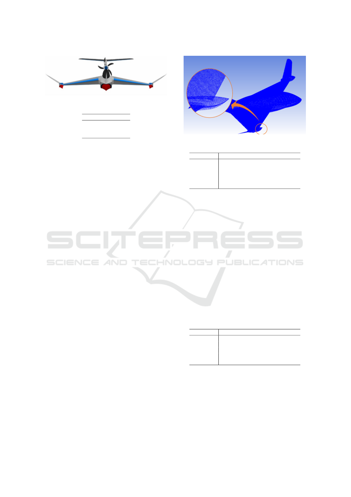
Figure 1: WISE (Trimaran) Craft Model
Table 1: Foil Shapes Modification on WISE’s Wings
No. Foil Shape
1. NACA 0006
2. NACA 4412
3. NACA 6409
3 COMPUTATIONAL FLUID
DYNAMIC
3.1 Geometry and Modelling
Prior to the CFD analysis carried out for prediction
of the lift force, 3D hull form of the trimaran vessels
was generated with CAD software. The trimaran ves-
sels are designed to have ailerons on her starboard and
port to help her maneuvers. In addition, in the tail sec-
tion of the vessel is given a pitching stabilizer which
is useful to help the vessel in the process of taking
off and landing. The vessel’s propeller is located on
the top of the vessel and is supported by a rudder on
the back of the vessel. The WISE craft 3D model is
shown in Figure 1.
In this paper, the 3D hull forms were developed
with 3 (three) modifications of foil shapes on her main
wings, as in Table 1. The modifications on her wings
are expected to minimize the craft’s resistance, thus
increasing the lift forces. At the end of the research,
the most optimum wing shape will be selected to be
made a prototype.
3.2 Mesh Generation
The next stage after the 3D model is created is to di-
vide the model geometry into small elements (trian-
gles, tetra/mixed, hexa-dominant) called a cell. These
cells form a unity called mesh or grid due to their
configuration which looks like mesh, thus this process
stage is commonly called as meshing. Mesh is of con-
siderate importance for computational purposes. The
mesh size of the vessel can be seen on Figure 2 below.
3.3 Boundary Condition
The model that has been meshed then will be set up
appropriate boundary conditions to run simulation of
free flight. The boundaries that were created namely:
Figure 2: Mesh Size of the Trimaran Vessel
Table 2: Boundary Condition
Boundary Type Conditions
Inflow Inlet Normal speed 16.2 knots
Outflow Outlet Static Pressure 0 Pa
Wall Wall Free slip wall
Ground Wall No slip wall, smooth wall
WISE Wall No slip wall, smooth wall
inflow, outflow, wall, top, and bottom. After the
boundaries have been made, each boundary will be
defined as can be seen on the Table 2 below.
4 COMPUTATIONAL RESULTS
AND ANALYSIS
4.1 Lift Force
The lift forces of the three WISE crafts are presented
in Table 3 with respect to varying the foil shape of her
main wings at her service speed, i.e 16.2 knots. As
it can be seen on the table, the highest lift force was
generated by NACA 4412, followed by NACA 6409,
and lastly, NACA 0006 placed at the bottom.
Table 3: Boundary Condition
Boundary Type Conditions
Inflow Inlet Normal speed 16.2 knots
Outflow Outlet Static Pressure 0 Pa
Wall Wall Free slip wall
Ground Wall No slip wall, smooth wall
WISE Wall No slip wall, smooth wall
4.2 Surface Pressure
Figure 3 up to Figure 5 provided an overview of
the total pressure distributions around the three crafts
with the same speed and height in cruise. WISE with
NACA 4412 wing foil shape indicated that higher
negative pressures were recorded along the vessel’s
SENTA 2018 - The 3rd International Conference on Marine Technology
156
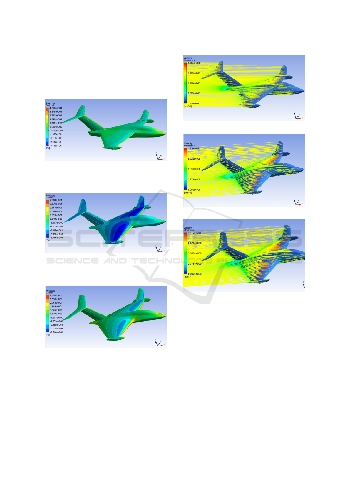
wing surface. Higher negative static pressure, cor-
responding to the reference static pressure from the
inflow, was found near the leading edge of the wing.
This results in an increase of lift forces on the wings
of the vessel.
Figure 3: Surface Pressure Distribution on WISE [NACA
0006]
Figure 4: Surface Pressure Distribution on WISE [NACA
4412]
Figure 5: Surface Pressure Distribution on WISE [NACA
6409]
4.3 Flow Visualization
Figure 6 up to Figure 8 show the flow pattern around
the three WISE crafts at the speed of 16.2 knots which
represents service speed.
Figure 6: Flow Patter around WISE [NACA 0006]
Figure 7: Flow Patter around WISE [NACA 4412]
Figure 8: Flow Patter around WISE [NACA 6409]
5 CONCLUSIONS
A detailed numerical investigation of the aerody-
namic characteristics of a WISE craft for various de-
sign of wing section using NACA series, it can be
summarized that NACA 0006 gives the lowest lift
forces and the design of NACA 6409 generate the
highest lift forces. Therefore, it can be concluded,
design of wing section using NACA 6409 more rec-
ommended for the WISE craft in speed 16.2 knots.
Numerical Study on the Section Design of a Wing in Surface Effect
157

REFERENCES
AKIMOTO, H., Kubo, S., and Kanehira, M. (2010). Wing
in surface effect ship with canard configuration. Interna-
tional Journal of Aerodynamics, 1.
Al-Atabi, M. (2006). Aerodynamics of wing tip sails. Jour-
nal of Engineering Science and Technology, 1.
Barber, T. and Hall, S. (2006). Aerodynamic ground ef-
fect: A case study of the integration of cfd and experi-
ments. International Journal of Vehicle Design - INT J
VEH DES, 40.
Fuwa, T. and Hirata, N. (1993). Fundamental study on
safety evaluation of wing-in-surface effect ship (wises).
In Proceedings of the Second International Conference
on Fast Sea Transportation (FAST 93).
Ho, C., Kim, K., and Lee, J. (2008). Effect of endplate
shape on performance and stability of wings-in ground
(wig) craft.
Irodov, R. (1974). Criteria of the longitudinal stability of
the ekranoplan. Ucheniye Zapiski TSAGI, 1:20.
Jung, K., Chun, H., and Kim, H. (2008). Experimental
investigation of wing-in-ground effect with a naca6409
section. Journal of Marine Science and Technology,
13:317–327.
KAWAKAMI, M. and AKIMOTO, H. (2006). Evalua-
tion of the canard type wing-in-surface-effect-ship by a
large self propulsion model and design of its experimen-
tal ship. In The 1st International Symposium on WIG
Crafts, page 2E2.
Kubo, S. and Rozhdestvensky, K. V. (1997). An outline
of conceptual design and feasibility analysis of a flying
wing configuration on the basis of extreme ground effect
theory. Proc. FAST’97, 2:503–511.
Kumar, P. (1972). Some stability problems of ground effect
wing vehicles in forward motion. Aeronautical Quar-
terly, 23:41–52.
Moore, N., Wilson, P., and Peters, A. (2002). An investi-
gation into wing in ground effect aerofoil geometry. In
RTO SCI Symposium on Challenges in Dynamics, System
Identification, Control and Handling Qualities for Land,
Air, Sea and Space Vehicles, pages 13–15.
Rozhdestvensky, K. (2000). Aerodynamics of a Lifting Sys-
tem in Extreme Ground Effect, pages 281–294.
Rozhdestvensky, K. (2006). Wing-in-ground effect vehi-
cles. Progress in Aerospace Sciences - PROG AEROSP
SCI, 42:211–283.
Staufenbiel, R. and Schlichting, U.-J. (1988). Stability of
airplanes in ground effect. Journal of Aircraft - J AIR-
CRAFT, 25:289–294.
Sun, C. and Dai, C. (2015). Experimental study on ground
effect of a wing with tip sails. Procedia Engineering,
126:559–563.
Withers, P. and Timko, P. (1977). The significance of
ground effect to the aerodynamic cost of flight and en-
ergetics of the black skimmer (rhyncops nigra). J. exp.
Biol, 70.
Yang, W., Yang, Z., and Collu, M. (2015). Longitudinal
static stability requirements for wing in ground effect ve-
hicle. International Journal of Naval Architecture and
Ocean Engineering, 7:0–0.
SENTA 2018 - The 3rd International Conference on Marine Technology
158
