
Comparative Study on Ferry Ro-Ro’s Car Deck Structural Strength
by Means of Application of Sandwich Materials
Tuswan
1
, Achmad Zubaydi
1
, Agung Budipriyanto
2
and Septia Hardy Sujiatanti
1
1
Department of Naval Architecture, Faculty of Marine Technology, Institut Teknologi Sepuluh Nopember (ITS), Jl. Arief
Rahman Hakim, Surabaya, Indonesia
2
Department of Civil Infrastructure Engineering, Faculty of Vocational Studies, Institut Teknologi Sepuluh Nopember (ITS),
Jl. Menur 127, Surabaya, Indonesia
Keywords: Car Deck, Structural Strength, Sandwich, Ferry Ro-Ro.
Abstract: This paper presents results of investigation on car deck performances by means of application of sandwich
materials for 300 GT Ferry Ro-Ro. Strength performance was examined utilizing finite element method and
compared to design criteria. Four finite element models of the ship deck were developed; three of them were
modification of existing ship structure with different configurations of stiffeners. Two design load cases were
considered in the analysis. Design load scenario was assumed to be in seagoing condition where the pressures
were due to the static and dynamic distributed loads. In this research, sandwich materials were fabricated from
steel face sheets and core materials which were made from two filler materials, one core was from clamshell
powder and the other was from eggshell powder. The synthetic resin was used as the matrix and epoxy resin
was applied as the adhesive layer. The results were promising in terms of structural strength and weight
savings. The strength of car deck sandwich structure having no deck beam was found to be met with the
allowable strength criteria and contributed to reducing the stress approximately 14.6%. Moreover, its
application led to the weight saving ranged from 8.87% to 11.6%.
1 INTRODUCTION
The lightweight material is urgently required.
Therefore, research effort concerning the application
of the lightweight material in ship’s deck structures
has recently attracted many researchers. Reducing the
mass of deck structures is the predominant intention,
but its application seems to be a major benefit to
decrease the ship lightweight due to a large number
of decks. Strength and stability of the structure and
weight reduction are a major consideration.
Consequently, in the most general cases, the
lightweight material is frequently selected instead of
increasing existing material thickness.
Lightweight materials (e.g. aluminium,
composite, and sandwich panel) have been
investigated as alternative materials in deck structure.
Gunnarsson and Hedlund (1994) investigated the
possibility the use of sandwich structure made from
extruded aluminium profiles in the ship’s car deck to
achieve a lower weight. However, the design was too
costly to be implemented. It was also assembled and
proved with acceptable results regarding structural
strength by Hanson (2000). Noury et al. (2005)
studied the comparison of a conventional stiffened
plate structure and the steel sandwich structure in the
hoistable car deck. The results indicated that weight
saving was about 10%. It was also showed that the
laser-welded sandwich panels offered high stiffness
and strength both local and global directions.
Momčilovic and Motok (2009) assessed the
application of sandwich plate system (SPS) in general
cargo barge and offered weight reduction from 5 to
15% in comparison to conventionally built one.
Weight reductions of the SPS bulk carrier and SPS
container barge were even less: 6 to 13% and 4 to
12%, serially. Based on the issues, it was hard to find
that it could be greater than 15%, mostly varying
between 5 and 8%. Kortenoeven et al. (2008) also
noticed that the application of sandwich material
could reduce the structural weight up to 39% in a
specific part (e.g. decks) of a dredging ship. Weight
reduction for FRP sandwiches could be more than
70% and average 39% for steel sandwich
applications. Hybrid sandwich (steel-polymer-steel)
has also been inspected, but the issues indicated that
Tuswan, ., Zubaydi, A., Budipriyanto, A. and Sujiatanti, S.
Comparative Study on Ferry Ro-Ro’s Car Deck Structural Strength by Means of Application of Sandwich Materials.
DOI: 10.5220/0008542800870096
In Proceedings of the 3rd International Conference on Marine Technology (SENTA 2018), pages 87-96
ISBN: 978-989-758-436-7
Copyright
c
2020 by SCITEPRESS – Science and Technology Publications, Lda. All rights reserved
87
there was no cost or weight advantage for internal
decks and bulkheads mainly because of the small
plate thickness needed in the existing structure.
Sandwich panels were also more excellent in terms of
weight savings than single-skin panels in most
structural parts of the ship, with an exception in
bottom structures constructed for high design
pressures, single skin panels were more
recommended as asserted by Johnson and Ringsberg
(2017).
Until now, more than 35,000 m2 of SPS are
currently in operation in the marine and construction
sectors. SPS has found substantial applications in ship
repair (e.g. ramps and Ro-Ro decks) using the overlay
technique. Further, it was a viable alternative to
conventional stiffened plates with further enhance
before it could be used in the construction of a new
car deck structure. SPS was a robust design that
reduces weld volumes by up to 60% compared to
stiffened plates (SAND.CORe, 2013). Its application
in ship structure also could (a) remove the need for
secondary stiffeners (Sujiatanti, et al., 2018), (b)
reduce the lightship weight (Brooking & Kennedy,
2004), (c) offer high strength to weight ratio
(Castanié, et al., 2008; Wadley, 2006; Mamalis, et al.,
2002; Belouettar, et al., 2009), and (d) improve
crashworthiness in structure (Reis & Rizkalla, 2008).
This paper presents the main issues to evaluate the
possibility of replacing today’s conventional steel car
deck panels in Ferry RO-RO vessels with alternative
lightweight sandwich materials. These materials were
satisfying the design requirements of scantlings, as
well as the classification society DNV-GL structural
strength for car deck panels (DNV-GL, 2015). The
design loads were calculated by adopting the DNV-
GL standard (DNV-GL, 2017). This paper is
organized as follow, aims and the used methodology
are explained. Then the reference model, load case
applied, material selection, and car deck’s modified
models are described. Next, the analyses and results
of structural strength and weight estimation are
systematically presented and discussed. This article is
concluded with conclusions.
2 DESCRIPTION OF MODEL
DEVELOPMENT
2.1 Reference Model
The ship used as a reference in this research was a
Ferry RO-RO with approximately corresponding to
the total car deck area of 381.8 m2. The car deck
panel comprised of two main parts; the stiffened plate
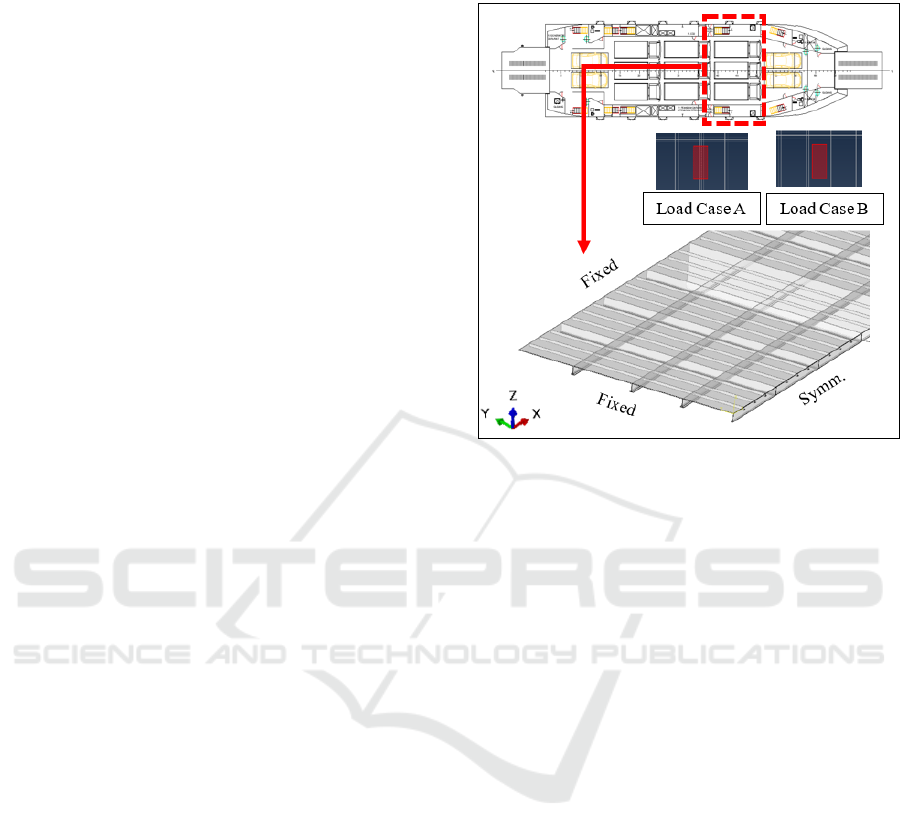
system and the beam system as illustrated in Figure 1.
Figure 1: Half-modelled reference car deck symmetric with
respect to x-axis with boundary condition and load case
variation.
The car deck structure investigated in this study
was located in the parallel mid-body between two
bulkheads; the dimension was 14 m in length and 11
m in breadth. In this research, the existing car deck
scantling consisted of deck girder and strong beam
with T profile (T 180x90x8 mm) and deck beam with
L profile (L 60x60x6 mm). The face sheet and core
thickness must be designed in accordance with the
strength index (R) by DNV-GL criteria (DNV-GL,
2016). The reference car deck thickness was 12 mm.
In this study, the sandwich thickness configuration
clearly calculated of 4 mm thin faceplate and 20 mm
thick core.
The modified models were based on the
configuration of stiffeners. Car Deck A was the
sandwich plate without changing the existing
stiffener, while Car Deck B was the car deck with
sandwich plate and diminished whole deck beams
without changing the strong beams and girder
spacing. Another modification was Car Deck C with
have similar configuration to Car Deck B but the
strong beam and deck girder’s frame spacing be
enlarged.
The finite element simulations were implemented
to analyze structural strength by comparing the von
Mises, normal stress, shear stress, and deflection
value between the existing steel structure and
modified models. Eight-node solid linear brick
elements with reduced integration and hourglass
SENTA 2018 - The 3rd International Conference on Marine Technology
88

control (C3D8R) having six degrees of freedom per
node was used to model the core material, A 4-node
doubly curved thin or thick shell with reduced
integration and hourglass control (S4R) was selected
to model steel plates, and a 2-node linear beam
element (B31) with six degrees of freedom per node
was used to model the stiffeners.
A node-surface based tie constraint was applied to
provide the interaction between the deck plate and
stiffener while surface to surface based tie constraint
was chosen to give interaction between faceplate and
core material as cohesive interaction. Meanwhile, the
assumption of boundary condition should be
organized in such a way that could be similar to the
real conditions. The boundary conditions applied in
the model were fixed in the side of car deck structure,
a pinned constraint in the connection between the
bulkhead and car deck, and symmetry constraint was
applied in the centre line of car deck structure.
2.2 Material Selection
The face sheets are comparatively thin and are usually
constructed by a high strength material. The core is
relatively thick and supports sufficient stiffness and
strength in the direction normal to the plane of the
face sheet.
In this study, both the conventional stiffened steel
plate car deck structure and the application of
sandwich material were systematically investigated.
The sandwich materials were manufactured by steel
facing plates and the core made from waste materials.
Two core materials were developed; one core
material was made synthetic resin and clamshell
powder and the other was made from synthetic resin
and eggshell powder. Many researchers were being
interested in eggshell and clam shell’s abilities as
potential fillers (Manshuri & Amalina, 2014; Hassan,
, et al., 2012). The most valuable properties including
hardness, water absorbent qualities, tensile strength
were found to be satisfied by using different sea shells
(Ramnath, et al., 2018). The filler was mixed with
unsaturated polyester resin (UPR) as matrix, methyl
ethyl ketone peroxide as a catalyst with different
weight compositions. The previous research
(Abdullah, et al., 2017; Mula, et al., 2017) stated that
filler ranged from 20% to 30% of the total core weight
of both clamshell and eggshell was the most optimum
composition core material properties and fulfilled the
DNV-GL Criteria (DNV-GL, 2016) and Lloyd’s
Register (Llyod’s Register, 2015).
Sandwich flexural tests in previous research were
performed to obtain core material properties of both
clamshell (Abdullah, et al., 2018) and eggshell (Mula,
et al., 2018) based on ASTM standard (ASTM C 393,
2016). Meanwhile, the mechanical properties of steel
were based on DNV-GL standard (DNV-GL, 2016).
The steel and core material properties used in finite
element modelling was obtained from previous
research, see in detail in (Abdullah, et al., 2018; Mula,
et al., 2018).
2.3 Load Estimation
Design load scenarios for strength calculation of car
deck in normal operation at sea were calculated. The
pressure due to the distributed load for the static and
dynamic design load scenario should be derived for
each dynamic load case and calculated as depicted in
Equation 1 (DNV-GL, 2017).
!
"#
$%
!
"#&'%
(
%!
"#&"%
(1)
where P
dl-s
is a static pressure due to the distributed
load. Dynamic pressure (P
dl-d
) due to the distributed
load is calculated by (P
dl-s
· a
z
/g), where a
z
represent
vertical envelope acceleration.
The load was assumed to in the seagoing
condition where the total load was the sum of static
pressure (P
dl-s
) from and dynamic pressure (P
dl-d
)
represented the motion of the ship. The panel was
loaded with a uniformly distributed load of 250 kg/m
2
and the self-weight of the panel. The total load was
calculated as self-weight= 131.7 tonne. Hence, the
dynamic factor was 1.5 in accordance with DNV-GL
(DNV-GL, 2017), and was added to the loads when
evaluating stresses. Therefore, arising due to the
motion of the ship increased the load to 197.55 tonne.
For stowed position load case, the local loaded
panel for a heavy truck was lifted to the stowed
position. In this load case, dynamic factor was not
used as a added load. The wheel load was designed
when the wheels from three heavy trucks were
situated in the top op stiffener (real contact between
tires and stiffener), hereinafter referred to as load case
A. Another case was situated exactly in the middle
between stiffener (axle parallel to stiffener),
hereinafter referred to as load case B, as depicted in
Figure 1.
For individual vehicles with specified
arrangement and dimensions of footprints, the local
design pressure (P
dl-s
) was, in general, to be taken as
(DNV-GL, 2015):
p
dl-s
=
Q
N
o
ab
(9.81+0.5a
v
)
(2)
Comparative Study on Ferry Ro-Ro’s Car Deck Structural Strength by Means of Application of Sandwich Materials
89
where Q represents maximum axle load in tones, n
o
is
number of load areas on the axle, a is the extent of the
load area parallel to the stiffeners in m, b is extent of
the load area perpendicular to the stiffeners in m, a
v
is
used for moving cargo handling vehicles, is assumed
to be 0. The load area dimensions are in general to be
taken as:
)%$
*
+%,
;
-
%$
.
,/+
(3)
where k is 2.0 for single wheel, 2.0 for multiple
wheels with axle parallel to stiffeners. A is calculated
by (9.81wQ/n
o
p
o
). Where n
o
is assumed to be 2 unless
otherwise specified. w value equals to 1.0 in general,
p
o
is divided by two load prints i.e. front load print
and rear load print which represent maximum tire
pressure in kN/m
2
. The summary of wheel loading
was presented in Table 1.
Table 1: Wheel loading of car deck.
Load
Prints
Chassis
Weight
(tonnes)
Weight
Capacity
(tonnes)
n
o
p
o
(kN/m
2
)
front
2.22
2.29
2
342.74
rear
1.66
4.51
2
234.54
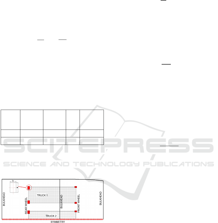
The load prints (in red area) of three heavy truck
used double wheel with dimension 0.3 x 0.425 m in
rear wheel and single wheel with dimension 0.3 x
0.215 m in front wheel as illustrated in Figure 2.
Figure 2: Working position of wheel loading of half-
modelled symmetric with respect to x-axis.
2.4 Design Criteria
Since the car deck structure was assumed to be
subjected to a pure vertical force, the only stress that
was evaluated in the initial design was normal
bending stress and bending shear stress. The normal
bending stress, denoted σ
x
was calculated with
Equation 4.
σ
x
=
M
y
I
y
z
(4)
where I
y
%
is the moment of inertia for the cross-section,
M
y
%
is the bending moment, and z is the distance from
the neutral axis to the fiber currently being studied in
the cross section (Thelandersson, 1987).
The bending shear stress
0
τ
xz
1
in the structure due
to a load of tire was calculated using Equation 5.
2
34
$%
5
6
%'
4
789
4
(5)
where v
y
is the load
:
s
z
%
is the static moment, I
z
%
is the
moment of inertia, and t is the thickness where the
shear stress is evaluated.
Besides normal and shear bending stress, and von
Mises stresses will occur when the profile was
unevenly loaded. Consequently, the equivalent von
Mises stress is evaluated with Equation 6. Where σ
y
=
σ
z
= τ
yz
= τ
xy
= 0, this assumption was decided since
the profile will be subjected to pure bending in this
load case. The von Mises stress was calculated with
Equation 6 below.
%;
5<
$
%
.
;
3
=%
(
>2
34
=%
%
(6)
Design criteria for analyzing structural strength
has to be defined. These criteria are determined in this
study by the classification society DNV GL
(Kortenoeven, et al., 2008). The maximum stresses
that are allowed to occur in the structural elements
were calculated according to DNV rules for existing
car deck. Maximum allowable stresses with regards
to load conditions for the existing car deck were
normal bending stress (σ
x
) is assumed 222 MPa,
bending shear stress
0
τ
xz
1
was assumed 125 MPa, and
von Mises stress was assumed 250 MPa.
To determine the permissible stress of modified
models by means of application of sandwich material,
the flexural test based on ASTM C393 (2016)
standard was conducted to obtain maximum
sandwich bending stress as permissible criteria.
Flexure tests on flat sandwich construction were
conducted to determine maximum face bending stress
(σ
nu
) and core shear stress (τ
u
). The permissible
criteria of modified models were summarized in
Table 2.
SENTA 2018 - The 3rd International Conference on Marine Technology
90
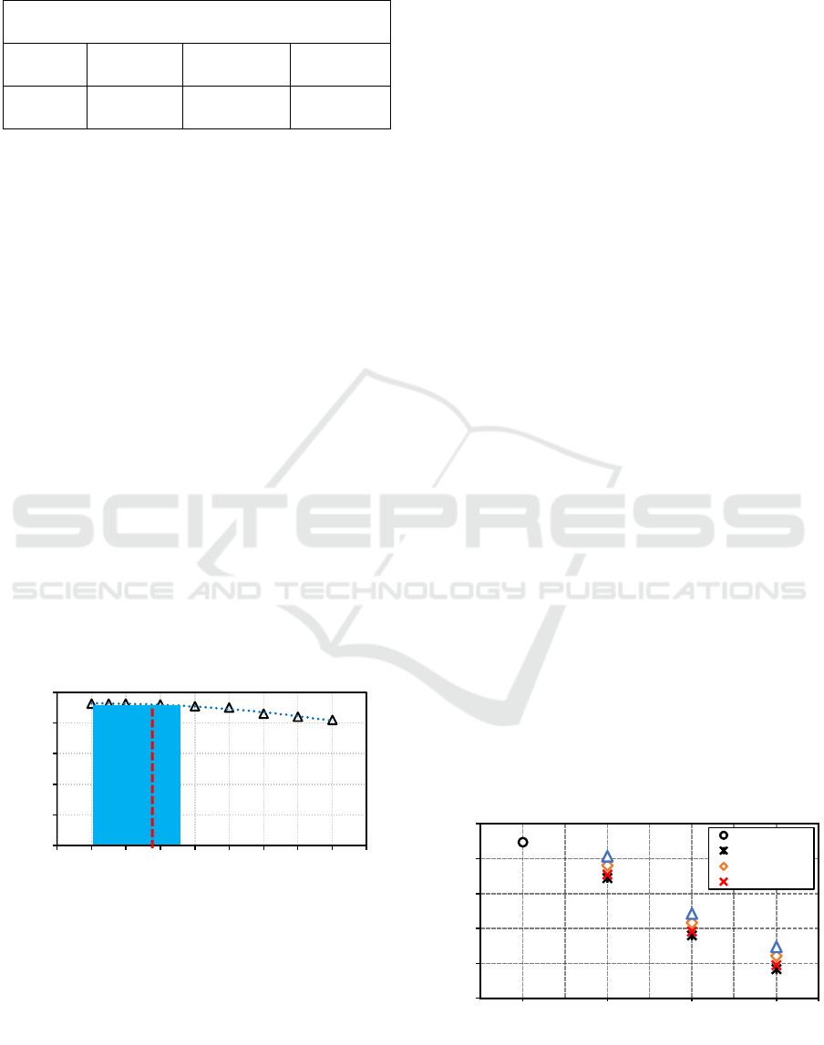
Table 2: Permissible stress of sandwich structure for
different core compositions.
Permissible criteria for sandwich with core
made from
20%
Eggshell
30%
Eggshell
20%
Clamshell
30%
Clamshell
90.7
MPa
95.2 MPa
67.6 MPa
71.4 MPa
The design criteria for deflection was assumed
that when the panel deflects, a certain free height
above the below car deck has to remain. Thus, a
certain limiting value could not be assigned precisely
for deflection (Ringsberg, 2015.). The maximum
edge deflection criteria of the lowest points of the
panel (δ) which must not exceed 50 mm was applied.
It applies to keep the difference in edge heights
between two adjacent loaded and unloaded car decks’
minimum. This was to ensure the safe passage of
vehicle from one panel to another.
2.5 Mesh Convergence Study
Mesh convergence is an important issue that needs to
be addressed in most of linear problem. During
performing an FE-analysis, there were possible
sources for error, for example, the mesh might be too
coarse. In order to obtain reliable results, a mesh
convergence study was carried out in order to confirm
the accuracy of the results. The method of
establishing mesh convergence required a curve of a
critical result parameter (von Mises stress), to be
plotted against global mesh size as can be seen from
the Figure 3.
Figure 3: Convergence study of reference model.
The vertical dashed line represented the optimum
global mesh size for the model. It was evident that the
solution converges for mesh sizes between 0.035 and
0.01 as illustrated by blue area in the Figure 3. For the
analysis, a global mesh size of 0.03 was applied in
finite element analysis.
3 RESULT AND DISCUSSION
Prior to the application of sandwich structure to ship
construction, preliminary strength analysis and
weight estimation were conducted to ensure that the
specific sandwich application in deck structure would
lead to substantial benefits for the shipyard as well as
the ship owner. Weight saving should be significant
to compensate the unforeseen technical, practical and
financial problems during the engineering and
production of sandwich applications and to assure
ship owner, classification societies and management
of the shipyard to actually decide to apply sandwich
panels.
Structure weight (m) is the relationship between
the density of the substance (ρ) and how much space
it takes up (v). The car deck total area as depicted in
Figure 1 was 381.8 m
2
and the density of the material
was reported in (Abdullah, et al., 2018; Mula, et al.,
2018).
The weight comparisons between the reference
car deck and three models of sandwich structures by
means of application of sandwich material and
configuration of stiffener are illustrated in Figure 4.
From the illustrated diagram, it could be reviewed
that the application of sandwich material both of
using clamshell and eggshell core material
considerably decreased the car deck weight. It could
be concluded that core material with 20% eggshell
which had the lowest density was the most significant
weight reduction compared to the others. In another
hand, the core material with 30% had the lowest
weight savings. Regarding the modified models, Car
Deck A without changing the configuration of
stiffener showed the marginally decrease the weight
from 1.7% to 4.5% in compared with existing car
deck. A similar report was also given in Car Deck B,
weight saving was in the range between 8.87% and
11.6%. Moreover, Car Deck C indicated the highest
weight reduction was about 15.8%.
Figure 4: Comparison of weight estimation to whole
models.
100
110
120
130
140
150
0.00 0.01 0.02 0.03 0.04 0.05 0.06 0.07 0.08 0.09
σ
vm
(MPa)
Global mesh size (mm)
Mesh size
convergence area
37
39
41
43
45
47
Existing Car
Deck
Car Deck A Car Deck B Car Deck C
Weight (tonnes)
Modified Structures' Models
Steel
Eggshell 20%
Eggshell 30%
Clamshell 20%
Comparative Study on Ferry Ro-Ro’s Car Deck Structural Strength by Means of Application of Sandwich Materials
91
Compared with similar reports regarding the
application of sandwich plate using synthetic resin,
Sujiatanti et al. (2018 stated that the result of the study
showed that the application of sandwich panel which
used core material from synthetic resin in Ro-Ro’s car
deck reduced the structural deck about 12%. It was a
correct projection of application of a waste material
as a filler in core material as a comparable result
regarding weight reduction. However, one has to
consider the reality that even though SPS proposes
valuable benefits, the rough weight reduction even
greater than 50% that can be occasionally discovered
in application of SPS in ship structure as argued by
Momčilović & Motok (2009).
With the weight reduction of the ship, an increase
in the ship's payload can be carried out in ship
operations, so that it can carry more cargo. It provides
meaningful benefits to the ship owner and shipyard.
Taking into consideration of sandwich
application, preliminary strength calculations used
finite element analysis was performed in the next
section and need further investigation to decide to
implement sandwich panels in car deck structures.
3.1 Structural Strength Analyses
One of the challenges for sandwich panel structures
is its sensitivity to point loads, i.e. concentrated loads
may break the material and cause delamination.
Therefore, besides weight analysis, the structural
strength analyses of the car deck by means of
application of sandwich material is substantially
important as an advance thorough check to study the
implementation of sandwich material.
In this section, the finite element analysis results
were presented to thoroughly observe the comparison
of structural strengths between existing car deck and
modified structures’ models where there were
different core material properties, and the number of
stiffener configurations. Permissible criteria for
different models, to investigate their performance and
to correlate them with each other, have to be defined
in Section 2.3.
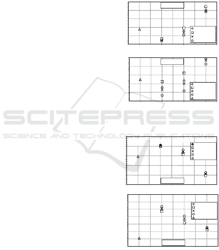
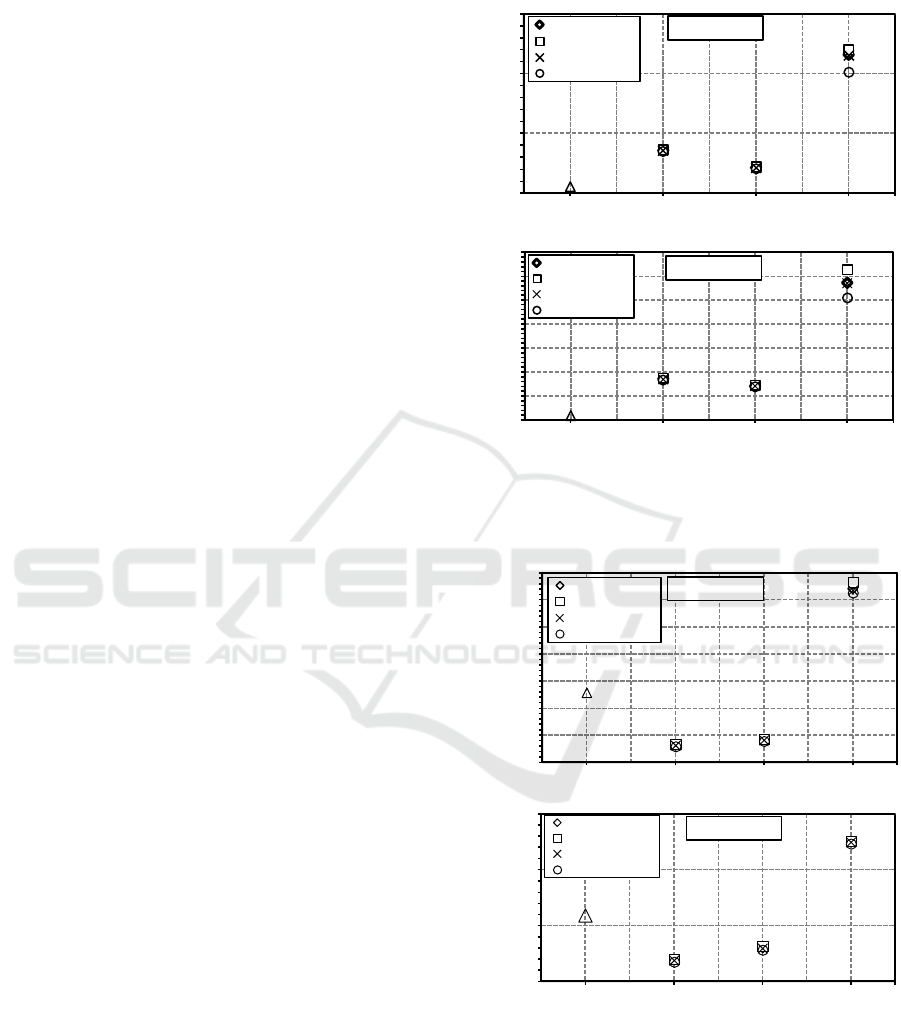
The results from the FE analyses between two
different load cases showed in Figure 5-8. Figure 5-7
presented in sequence the comparison of von Mises
stress (σ
?@
), normal bending stress (σ
x
), and shear
bending stress
0
τ
xz
1
between existing model and
modification models. From those illustrated
diagrams, in comparison between the existing model
and Car Deck A which have similar stiffener
configuration, the application of sandwich material
could reduce von Mises stress in the range from 13%
to 15.8% in load case A, and from 1.3% to 9.5% in
load case B, respectively. It could be reviewed that
Load Case B which wheel load was situated exactly
in the middle between stiffeners (axle parallel to
stiffener) identified as the most critical concern. This
is not a standard cargo configuration and will occur
very seldom.
Figure 5: von Mises Stress between existing and modified
structures’ models under (a) Load Case A (b) Load Case B.
Figure 6: Normal bending stress between existing and
modified structures’ models under (a) Load Case A (b)
Load Case B.
70
80
90
100
110
120
Existing Car
Deck
Car Deck A Car Deck B Car Deck C
σvm (MPa)
Configuration Models (a)
Load Case A
20% Eggshell
20% Clamshell
30% Eggshell
30% Clamshell
85
90
95
100
105
110
Existing Car Deck Car Deck A Car Deck B Car Deck C
σvm (MPa)
Configuration Models (b)
Load Case B
20% Eggshell
20% Clamshell
30% Eggshell
30% Clamshell
Steel
-90
-80
-70
-60
-50
-40
Existing Car
Deck
Car Deck A Car Deck B Car Deck C
σx (MPa)
Configuration Models
Load Case A
20% Eggshell
20% Clamshell
30% Eggshell
30% Clamshell
Steel
-120
-110
-100
-90
-80
-70
-60
-50
Existing Car
Deck
Car Deck A Car Deck B Car Deck C
σx (MPa)
Configuration Models
Load Case B
20% Eggshell
20% Clamshell
30% Eggshell
30% Clamshell
Steel
SENTA 2018 - The 3rd International Conference on Marine Technology
92
The reduction of stress by sandwich application is
influenced by the difference in thickness
configuration between steel and sandwich plates and
separation of the face plates by a lightweight core acts
to significantly increase sectional modulus and
sectional area which can improve bending stiffness of
the material cross-section. Its application will also
remove the sources of stress concentrations so that
can decrease the stress which occurs in the structure.
In comparison with design criteria in the existing
model, the von Mises stress, normal bending stress,
and shear bending stress which occurred in the
existing structure were still below than design
criteria. In addition, concerning the von Mises stress
occurred in modified models for each load case, the
possible modification model was effective in Car
Deck B. The stress occurred in whole sandwich types
in Car Deck C exceed the permissible criteria. In Car
Deck B, only sandwich with 30% eggshell had stress
value below the permissible criteria for each load case
with stress reduction about 14.6% in load case A, and
6% in load case B, serially. Figure 5 also showed that
diminishing the stiffener in modification model will
increase the von Mises stress. Compared with
existing model, the same study was carried out by
Zubaydi et al. (2018) who studied the application of
sandwich plate for redesigning the car deck. There
was no weight saving calculation in this research. The
core consisted of unsaturated polyester resin and talc
with four filler variations was used. The stress
reduction was mostly varying between 19.9% and
20.7%. The higher weight reduction was caused by
using thicker sandwich thickness compared with this
project.
It can be further noticed in Figure 6 and Figure 7
which showed the comparison of normal bending
stress (σ
x
) and shear bending stress
0
τ
xz
1
in whole
models. Comparing the existing structure and Car
Deck A, the application of sandwich material in car
deck structure will decrease the normal bending stress
and increase the shear bending stress. Zero normal
bending stress will occur in the neutral axis and the
stress level will increase as the distance from the
neutral axis increases.
Further, Figure 8 illustrated the deflection value
which occurred in whole models. The main
consideration for investigating the deflection is to
evaluate how a car will react while passing a panel. If
the deflection is large, the car will experience an up
and down motion of the vehicle, which can be
uncomfortable. Another goal for investigating the
deflection is for visualization function. If the
deflection is large and visible to the eye, the structure
could be noticed as unreliable, which is unsatisfactory
for the ship owner.
Figure 7: Shear bending stress between existing and
modified structures’ models (a) Load Case A (b) Load Case
B.
Figure 8: Maximum deflections between existing and
modified structures’ models under (a) Load Case A (b)
Load Case B.
The stiffness of the structure is dependent on the
cross-section, and the lower the stiffness is the higher
will the deflection be. Figure 7 represented that
29
34
39
44
Existing Car
Deck
Car Deck A Car Deck B Car Deck C
τxz (MPa)
Configuration Models
Load Case B
20% Eggshell
20% Clamshell
30% Eggshell
30% Clamshell
30
32
34
36
38
40
42
44
Existing Car Deck Car Deck A Car Deck B Car Deck C
τxz (MPa)
Configuration Models
Load Case A
20% Eggshell
20% Clamshell
30% Eggshell
30% Clamshell
0.019
0.021
0.023
0.025
0.027
0.029
0.031
0.033
Existing Car
Deck
Car Deck A Car Deck B Car Deck C
U (m)
Configuration Models
Load Case A
20% Eggshell
20% Clamshell
30% Eggshell
30% Clamshell
0.019
0.024
0.029
0.034
Existing Car
Deck
Car Deck A Car Deck B Car Deck C
U (m)
Configuration Models
Load Case B
20% Eggshell
20% Clamshell
30% Eggshell
30% Clamshell
Comparative Study on Ferry Ro-Ro’s Car Deck Structural Strength by Means of Application of Sandwich Materials
93
application of sandwich material in car deck structure
could increase the stiffness by reducing the deflection
compared to existing model; 15.9%-16.5% in load
case A, 15.7%-16.7% in load case B, respectively.
Compared with permissible criteria, all models in
each load case fulfilled the maximum edge deflection
criteria of the lowest points of the panel (δ). It also
reviewed that deflection in Car Deck A and Car Deck
B was still lower than the existing model. Further, the
deflection in Car Deck C significantly increased the
deflection compared to existing model.
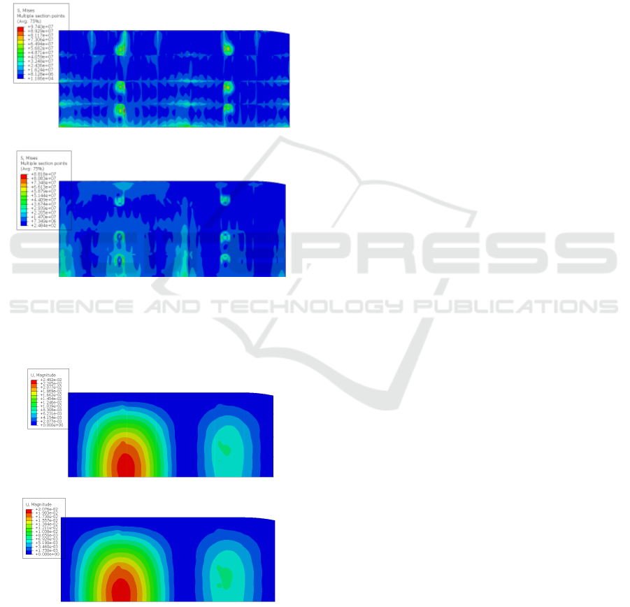
(a)
(b)
Figure 9: Comparison of half-modelled von Mises stress
contour in Load B (a) Existing (b) Car Deck A with 30%
Clamshell.
(a)
(b)
Figure 10: Comparison of half-modelled deflection contour
in Load B (a) Existing (b) Car Deck A with 30% Clamshell.
The comparison of half-modelled von Mises
stress and deflection contour between existing model
and Car Deck A in Load Case A was figure out in
Figure 9 and Figure 10. From the illustrated figure, it
showed that the highest stress occurred in the
connection of deck plating and stiffener near wheel
load. The application of sandwich material removes
the sources of stress concentration as depicted in
Figure 9b so that can decrease the stress occurred in
the structure. Similarly, the comparison of deflection
contour by means of application of sandwich
materials was also presented in Figure 10. It was
clearly seen that the application of sandwich material
could significantly decrease the deflection value. The
deflection contour presented that the highest
maximum deflection has occurred in an area which
experienced the rear wheel loading. It was affected
because the in the rear wheel had the higher load print
than in the front wheel.
4 CONCLUSIONS
This is to summarized primary observations and
conclusions from this research, considering the
assumptions made and work limitation regarding the
projection of application of sandwich material in car
deck structure. The preliminary study regarding the
application of sandwich material as an alternative
solution in deck structure indicated a very promising
results in terms of structural strength and weight
saving. The FE method had been utilized to model
and analyze the influence of sandwich application on
a reference car deck with respect to design criteria
such as the normal, shear, von Mises stresses, and
deflection occurring in the structure. The best car
deck configuration was obtained by eliminating all
the deck beams by using sandwich with 30%
eggshell. Its application contributed to stress
reduction about 14.6% in load case A, and 6% in load
case B. However, Load case B was not a standard
cargo configuration and would occur very rarely. In
terms of rough weight estimation, its application
showed that the weight savings were in the range of
8.87% and 11.6%.
Further studies on parametric design and cost
optimization need to be carried out. By utilizing
optimization techniques, a relatively better solution
could be reached as the optimum dimensions for car
deck configuration is found.
SENTA 2018 - The 3rd International Conference on Marine Technology
94

ACKNOWLEDGEMENTS
This research was funded by Directorate of
Research and Community Services, Ministry of
Research, Technology and Higher Education, The
Republic of Indonesia under PUPT research scheme.
The first author would like to thank for the support
provided by the Ministry through The Master’s
Degree Program Leading to Doctoral Degree for
Excellent Bachelor Graduates (PMDSU).
REFERENCES
Abdullah, K., Zubaydi , A. & Budipriyanto, A., 2017.
Development of Sandwich Panel with Core from
Clamshell Powder for Ship Structure. International
Conference on Marine Technology. Surabaya.
Abdullah, K., Zubaydi, A. & Budipriyanto, A., 2018.
Development and Dynamic Analysis of Sandwich
Panels which Core Material Made from Clamshell in
Ship Construction. Department of Naval Architecture,
Institut Teknologi Sepuluh Nopember. Surabaya.
ASTM C 393, 2016. Standard Test Method for Core Shear
Properties of Sandwich Constructions by Beam
Flexure. West Conshohocken. ASTM International.
USA.
Belouettar, S., Abbadi, A., Azari, Z. & Belouet, R., 2009.
Experimental Investigation of Static and Fatigue
Behaviour of Composites Honeycomb Materials Using
Four Point Bending Tests. Composite Structures,
Volume 87 No. 3, pp. 265-273.
Brooking, M. & Kennedy, S., 2004. The Performance,
Safety and Production Benefits of SPS Structures for
Double Hull Tankers. Royal Institution of Naval
Architects. London, UK.
Castanié, B., Aminanda, Y., Bouvet, C. & Barr, J. J., 2008.
Core Crush Criterion to Determine the Strength of
Sandwich Composite Structures Subjected to
Compression After Impact. Composite Structures,
Volume 86 No. 1-3, pp. 243-250.
DNV-GL, 2015. Rules For Classification High Speed and
Light Craft. Part 5 Ship Types Chapter 2 Car Ferry ed.
DNVGL. Norway.
DNV-GL, 2016. Steel Sandwich Panel Construction.
DNVGL. Norway.
DNV-GL, 2017. Rules For Classification Ships. Part 3 Hull
Chapter 4 Loads ed. DNVGL. Norway.
Gunnarson, M., 1994. Beneficial Use of Aluminium in Ro-
Ro Equipment. Department of Naval Architecture and
Ocean Engineering, Chalmers University of
Technology. Göteborg.
Hakansson, M., Johnson, E. & Ringsberg, J. W., 2017. Cost
and Weight of Composite Ship Structures: A
Parametric Study Based on Det Norske Veritas Rules.
Journal of Engineering for the Maritime Environment,
pp. 1-20.
Hanson, K., 2000. Lifting Tires in Aluminum for Vehicle
Transport. Institutionen För Byggkonstruktion,
Kungliga Tekniska Högskolan. Stockholm.
Hassan, , S. B., Aigbodion, V. S. & Patrick, S. N., 2012.
Particulate Composite Development of
Polyester/Eggshell. Tribology in Industry, Volume 34,
pp. 217-225.
Kortenoeven, J., Boon, B. & De Bruijn, A., 2008.
Application of Sandwich Panels in Design and Building
of Dredging Ships. Journal of Ship Production, pp.
125-134.
Llyod’s Register, 2015. Provisional Rules for the
Application of Sandwich Panel Construction to Ship
Structure. Llyod’s Register.London.
Mamalis, A., Manolakos, D., Ioannidis, M. & Kos, P.,
2002. Axial Collapse of Hybrid Square Sandwich
Composite Tubular Components with Corrugated Core:
Numerical Modelling. Composite Structures, Volume
58, pp. 571-582.
Manshuri, Y. & Amalina, M. A., 2014. Hardness and
Compressive Properties of Calcium Carbonate Derived
from Clam Shell Filled Unsaturated Polyester
Composites. Materials Research Innovations, Volume
18, pp. 291-294.
Momčilović, N. & Motok, M., 2009. Estimation of Ship
Lightweight Reduction by Means of Application of
Sandwich Plate System. FME Transactions, Volume
37, pp. 123-128.
Mula, I. A., Zubaydi, A. & Budipriyanto, , A., 2017.
Properties of Sandwich Panel Core from Eggshell
Powder for Ship Structure,. International Conference
on Marine Technology. Surabaya.
Mula, I. A., Zubaydi, A. & Budipriyanto, A., 2018. Static
and Dynamic Analysis of Sandwich Panels Made of
Core Material from Eggshell in Flat Plate
Construction, Department of Naval Architecture,
Institut Teknologi Sepuluh Nopember. Surabaya.
Noury, P., Hayman, B., McGeorge, D. & Weitzenböck, J.,
2005. Lightweight Construction for Advanced
Shipbuilding-Recent Development. s.l.:Det Norske
Veritas.
Ramnath, B. V. et al., 2018. Sea Shells and Natural Fibres
Composites. Materials Today: Proceedings, Volume 5,
p. 1846–1851.
Reis, E. M. & Rizkalla, S. H., 2008. Material
Characteristics of 3-D FRP Sandwich Panels.
Construction and Building Materials, Volume 22 No.
6, pp. 1009-1018.
Ringsberg, J., 2015.. Steel or Composite Car Deck
Structure - A Comparison Analysis of Weight, Strength
and Cost. Analysis and Design of Marine Structures,
pp. 647-658.
SAND.CORe, 2013. Best Practice Guide for Sandwich
Structures in Marine Applications. s.l.:New Rail.
Sujiatanti, S., Zubaydi, A. & Budipriyanto, A., 2018. Finite
Element Analysis of Ship Deck Sandwich Panel.
Applied Mechanics and Materials, Volume 874, pp.
134-139.
Thelandersson, S., 1987. Analysis of Thin-Walled Elastic
Beams. Lund University. Sweden.
Comparative Study on Ferry Ro-Ro’s Car Deck Structural Strength by Means of Application of Sandwich Materials
95

Wadley, H. N. G., 2006. Multifunctional Periodic Cellular
Metals. Philosophical Transactions of the Royal
Society A, Volume 364, p. 31–68.
Zubaydi, A., Budipriyanto, A. & Iswidodo, W., 2017.
Sandwich Core Material Development for Ship Deck
Structure. The Third International Conference on Civil
Engineering Research (ICCER), pp. 86-91.
SENTA 2018 - The 3rd International Conference on Marine Technology
96
