
Thrust Analysis and Type of Kaplan Series and B Series Torque
Propeller on Monohull, Catamaran, and Trimaran Vessels with
Variations in Number of Blade using Computational Fluid Dynamic
Berlian Adietya, Deddy Chrismianto, Jatie Erlangga and Harno
Naval Architecture Department, Diponegoro University, 50275 Semarang, Indonesia
Keywords: Propeller, Monohull, Catamaran, Trimaran, CFD.
Abstract: One part of the propulsion system is a propeller. The choice of a good driving device will affect the force of
the ship. One way of selecting a ship propulsion is the selection of the propeller type as well as providing
new variations of the propeller to produce the maximum thrust force. Kaplan series and B Series are the
most widely used blade type propellers on ships. The purpose of this study was to determine the optimum
thrust value and the lowest torque from the variation of the monohull, catamaran and trimaran propeller
vessels. Variations made are adding the number of blades to 4 and 5. The model was simulated using the
computational fluid dynamic method on the Ansys CFX software. The results of this study indicate that the
monohull propeller K6 60 Series pitch ratio 0.7 has the greatest thrust value of 333797 N. For catamaran
ships, propeller K4 60 Series pitch ratio 0.6 has the greatest thrust value of 61986.4 N. For trimaran ships,
propeller K4 60 Series pitch ratio 0.6 has the greatest thrust value of 0.8727 N.
1 PRELIMINARY
Propeller efficiency is influenced by several things
including the shape of the ship's hull and the ship's
propulsion system itself.
In determining the optimal ship propulsion
system, propeller design planning is an important
aspect that needs attention. Ship propeller design is
also considered for ship operational needs in terms
of its economy (Hartono, 2008). Propeller is one
aspect that must be planned properly to achieve the
purpose of the ship's function in achieving speed.
The speed of the ship cannot be separated from the
good propeller design in order to get the optimal
thrust produced by propeller motion (Nurul, 2013).
Seen from its function, monohull, catamaran, and
trimaran vessels must have a good propulsion
system to produce optimal thrust values in the
propeller. Thrust is the driving force that results
from the lifting force on the back of the propeller
that moves and is in line with the movement of the
ship. One of the requirements that need to be
considered in the propeller design to get maximum
thrust is the number of blades (Trimulyono, 2015).
The greater the value of the blade area ratio, the
greater the thrust force (Bangkit et.al, 2016). The
previous Kaplan series type propeller design is the
addition of the propeller end plate (Andilolo, 2017).
In this study, the propeller planning made is to
do variations in the number of blade added. Blade
area ratio is the ratio between the blade area of the
propeller and the full rotation area of the blade tip or
commonly referred to as A0 (Bangkit et.al, 2016).
While the pitch ratio is the axial distance round the
propeller.
The study conducted is to do variations on the
existing propeller model. Variations made include
increasing the number of propeller blade to 4 and 5
blade.
The limitation of the problem in this study is to
only analyze the thrust and torque values of the
variation of the propeller model. This study also
ignores the factors and conditions of fluid flow from
the ship's hull and only analyzes the flow
distribution behind the propeller. The shape of the
propeller hub was also ignored in this study.
Propeller variation model will be analyzed using
computational fluid dynamic method. In this study
do not do the cost analysis calculation.
The purpose of this study was to obtain the
greatest thrust value and torque from the variation of
the propeller model that was carried out. This study
is expected to provide benefits in the development of
shipping technology, especially in the field of ship
Adietya, B., Chrismianto, D., Erlangga, J. and Harno, .
Thrust Analysis and Type of Kaplan Series and B Series Torque Propeller on Monohull, Catamaran, and Trimaran Vessels with Variations in Number of Blade using Computational Fluid
Dynamic.
DOI: 10.5220/0008373000210028
In Proceedings of the 6th International Seminar on Ocean and Coastal Engineering, Environmental and Natural Disaster Management (ISOCEEN 2018), pages 21-28
ISBN: 978-989-758-455-8
Copyright
c
2020 by SCITEPRESS – Science and Technology Publications, Lda. All rights reserved
21
propulsion. In addition, this study can be used as a
reference source in terms of consideration of the
selection of propellers that are appropriately applied
to ships and can also be a reference for propeller
producers to innovate propeller products to be
produced.
2 METHOD
2.1 Data Collection
The data needed for this study are the data of the
main size of monohull, catamaran and trimaran ship
propellers.
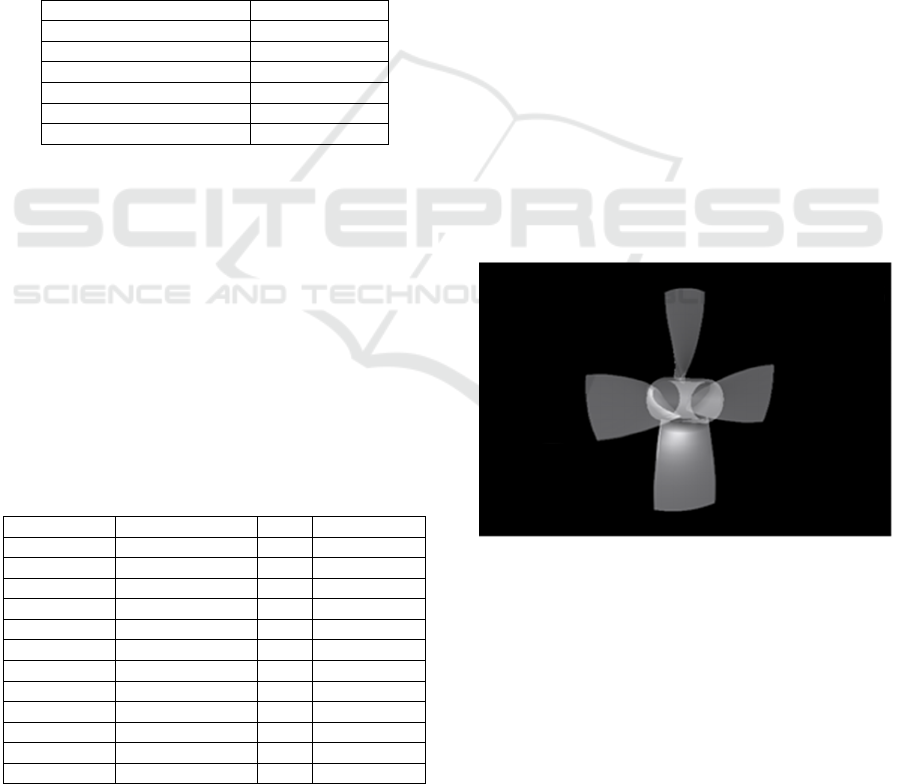
Table 1: Main Size Propeller B-Series.
Tipe B Series
Number of blade 4
Diameter 0,8 meter
Blade Area Ratio 0,70
Pitch 0,8
Angle of Rake 0
Propeller Rotation 0 rpm
2.2 Modelling and Variation
Modelling of the Kaplan Series propeller is based on
data from the main size of the propeller and the
addition of variations to the propeller. In this study
the parameters used are as follows:
• Constantly Parameter:
1. Main Size from ship propeller.
• Unconstantly Parameter
1. Number of blade 4 and 5
2. Rpm 600, 900, and 1000
3. Propeller type B-Series and Kaplan
Table 2: Shows Data on 12 Variations of the Kaplan
Series Propeller Model.
Model Number of Blade Rpm Propeller Type
Monohull 1 4 600 B-Series
Monohull 2 4 600 Kaplan
Monohull 3 5 600 B-Series
Monohull 4 5 600 Kaplan
Catamaran1 4 1000 B-Series
Catamaran2 4 1000 Kaplan
Catamaran 3 5 1000 B-Series
Catamaran 4 5 1000 Kaplan
Trimaran 1 4 900 B-Series
Trimaran 2 4 900 Kaplan
Trimaran 3 5 900 B-Series
Trimaran 4 5 900 Kaplan
2.3 Model Simulation
Analysis of variations in propeller models using the
Computational Fluid Dynamic method on the Ansys
CFX software. This method has often been used to
analyze fluid flow especially in thrust analysis and
torque propeller in previous studies.
2.4 Study Sites
This research was conducted at the hydrodynamic
laboratory, Department of Naval Architecture,
Faculty of Engineering, Diponegoro University,
Semarang.
3 RESULTS AND DISCUSSION
3.1 Model Making Stage
In making a propeller model, the main size of the
propeller is used as the initial data entered in the
PropCad software. Variations that will be applied to
the propeller are also modeled in this software. Then
a 3D propeller model will be produced along with
propeller geometry data. Here are the results of the
visualization of the propeller model from PropCad
software.
Figure 1: Propeller on Software Prop Cad.
After modelling the PropCad software, it was
repeated using Solidwork software to improve the
model. The propeller model made is 16 models with
variations in the number of blade, blade area ratio
and pitch ratio as well as 1 model with the addition
of nozzle kort. The following are the results of
visualization modelling using solidwork software.
ISOCEEN 2018 - 6th International Seminar on Ocean and Coastal Engineering, Environmental and Natural Disaster Management
22
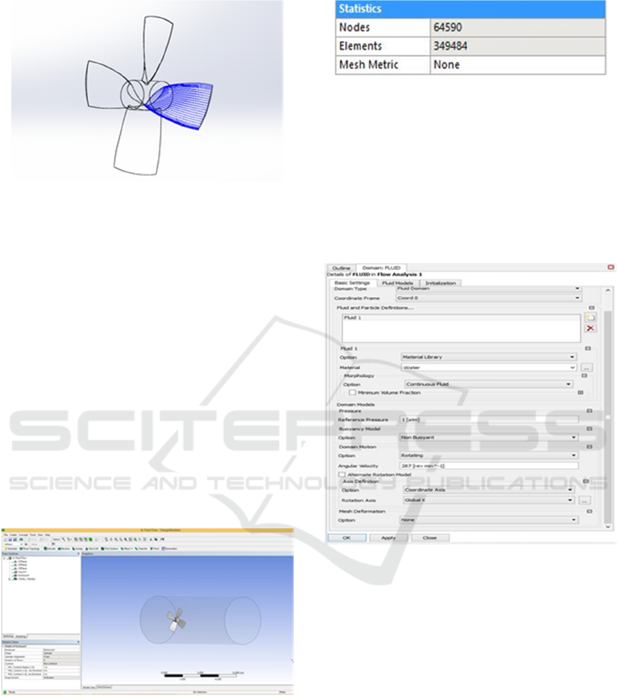
Figure 2: Propeller on Software Solidwork.
3.2 Simulation of Computational Fluid
Dynamics
The propeller model created in Solidwork software
then exported in the iges format to be imported into
the Ansys CFX software. The steps of propeller
simulation on Ansys CFX software include:
1. Geometry
2. Mesh
3. Setup
4. Solution
5. Result
3.2.1 Geometry Stage
At this stage the model entered must be solid. The
next step is to make a tubular fluid domain. The size
of the fluid domain is adjusted to the propeller
model to be analyzed.
Figure 3: Geometry Stage Visualization.
3.2.2 Mesh Stage
After the fluid domain is formed, the next is
meshing the model. The initial step in meshing is to
determine the size of the element used. The smaller
elements that are made running time are longer and
the file capacity is greater.
Figure 4: Meshing result statistics.
3.2.3 Setup Stage
In the setup stage data input will be used for
computational fluid dynamic simulations. The initial
step at this stage is to create a default domain.
Domains created include domains for fluids and
propellers. The next step is making boundaries.
Boundaries made include inlet, outlet and wall in the
domain fluid.
Figure 5: Default domain.
The next step is making initialization. The menu
is almost the same as the boundary. The final step is
the determination of the solver which one of its
functions determines the unit for measures in the
simulation process and control solver.
3.2.4 Solution Stage
The solution phase is a running calculation process
in the form of literacy from the basic equation of
computational fluid dynamic.
Thrust Analysis and Type of Kaplan Series and B Series Torque Propeller on Monohull, Catamaran, and Trimaran Vessels with Variations in
Number of Blade using Computational Fluid Dynamic
23
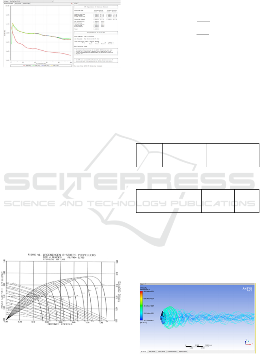
Figure 6: Convergence Running Model.
3.2.5 Result Stage
At the result stage the running results can be known.
The amount of thrust and torque can be obtained as
well as the model and flow visualization can be
displayed.
3.3 Propeller Validation
In this study the validation used was the result of
previous research. The main size of the propeller and
the main size of the ship in this study are the same as
previous studies. Validation is used to determine the
right boundary condition at the setup stage, so that it
can be used to analyze the propeller model analyzed
in this study.
Validation references for propellers use the
Wageningen B-Series graph. The propeller model
used is the Wageningen B4 70 Series type. The
maximum error for validation between
computational fluid dynamic and calculation results
is 5%.
In general, the characteristics of the ship
propellers in the open water test conditions are as
presented in the KT-KQ-J diagram.
Figure 7: Diagram Kt-Kq-J B4-70 (Bernitsas, 1981).
Mathematical calculations to find thrust and
torque are using the formula obtained from the
calculation of Wageningen B-Series. Equation
models for ship propeller performance
characteristics are as follows:
4
(1)
(2)
(3)
Where KT is the propeller thrust coefficient, KQ is
the propeller torque coefficient, J is the advance
propeller coefficient, Va is the advance (fr / s)
velocity, D is the propeller diameter (ft), n is the
propeller rotation (rev / s), T is the thrust propeller
(lbf), Q is the torque propeller (lbf / ft) and ρ is the
type of fluid.
The results of thrust and torque calculations on
computational fluid dynamic simulations and
mathematical calculations using Wageningen B-
Series charts are as follows:
Table 3: Thrust Propeller Validation (Wibowo et.al, 2017).
Rotation
Speed
(rpm)
The Calculation
Thrust Results
(N)
The CFD Result
(N)
Error
(%)
287 123006,49 122713,00 0,23
Table 4: Validation Torque Propeller (Wibowo et.al,
2017).
Rotation
Speed
(rpm)
The Calculation
TorqueResult
(Nm)
CFD
Simulation
Results (Nm)
Error
(%)
287 39646,94 40196,4 1,38
From the results of computational fluid dynamic
calculations compared to the results of mathematical
calculations of propellers using the Wageningen B-
Series graph, the margin of error is below 5%. This
means that the setup parameters in the computational
fluid dynamic calculation are quite accurate. Then
the setup parameter will be used in this study.
3.4 Results Analysis
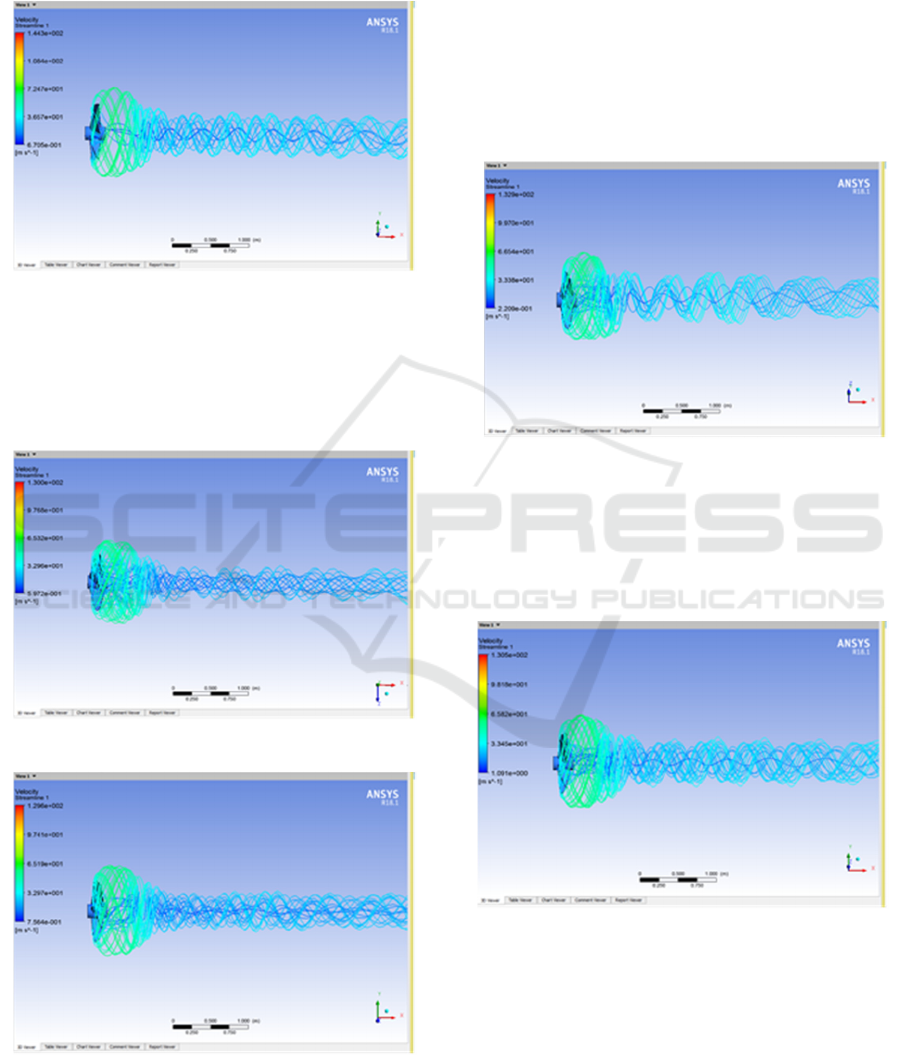
Figure 8: Result Streamline Monohull 1.
ISOCEEN 2018 - 6th International Seminar on Ocean and Coastal Engineering, Environmental and Natural Disaster Management
24
In the streamline model Monohull 1 has a less stable
and constant fluid flow. Fluid flow is less smooth
and turbulence is quite high in front of the propeller.
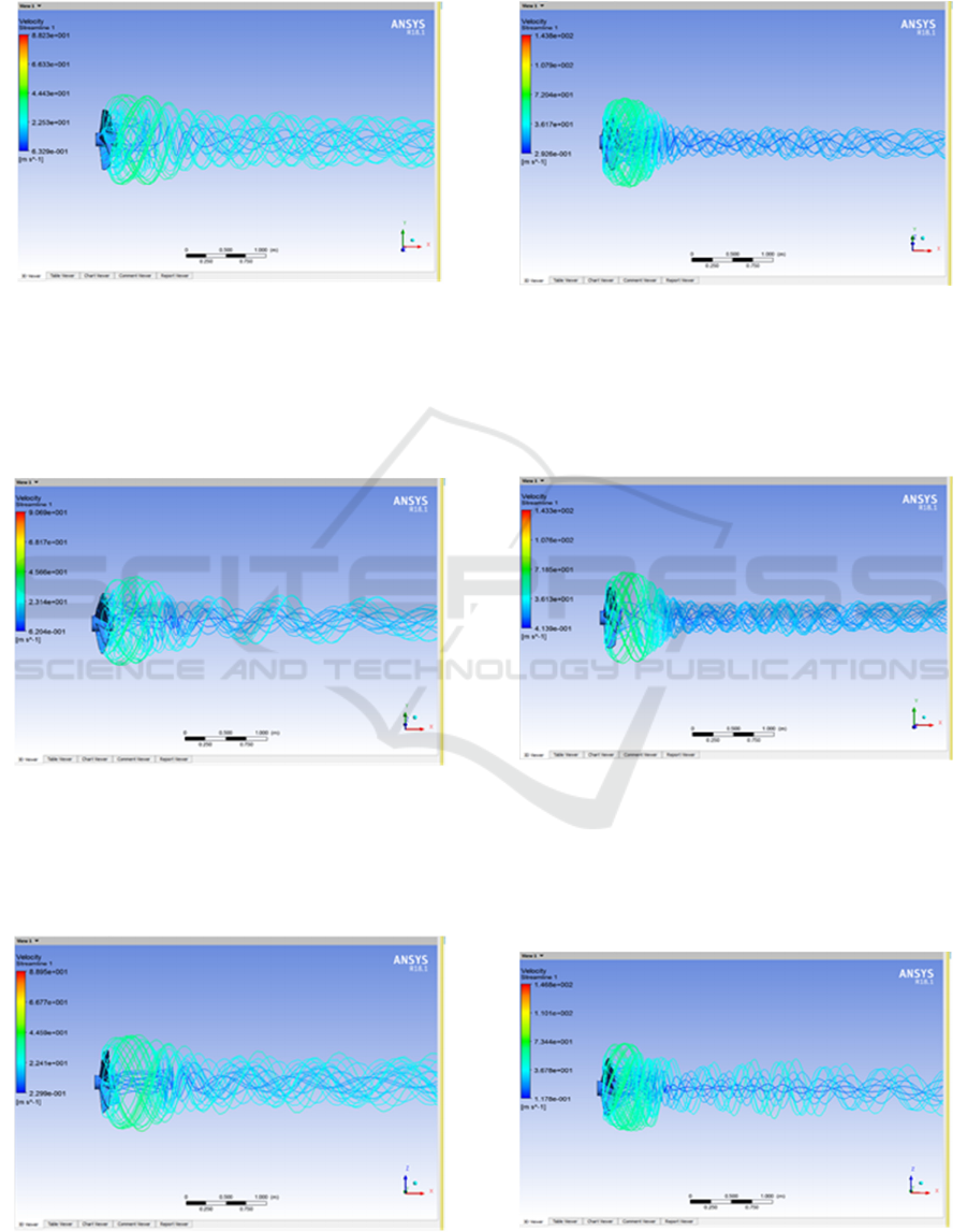
Figure 9: Result Streamline Monohull 2.
In the streamline model Monohull 2 has a stable
and constant fluid flow. Fluid flow is quite smooth
and turbulence is smaller than before especially the
area in front of the propeller and along the flow is
quite low.
Figure 10: Result Streamline Monohull 3.
In the streamline model Monohull 3 has a fluid
flow that is less stable and not constant. The fluid
flow is less smooth and the turbulence in front of the
propeller is quite high.
Figure 11: Result Streamline Monohull 4.
The streamline Monohull 4 model has a stable
and constant fluid flow. Fluid flow is smooth enough
and turbulence is quite low along streamlined flow.
Figure 12: Result Streamline Catamaran 1.
The streamlined propeller model of Catamaran 1
has a fairly stable and fairly constant fluid flow.
Fluid flow is still quite smooth but the emergence of
turbulence is very large especially in the front area
of the hub.
Figure 13: Result Streamline Catamaran 2.
In the streamlined propeller model of Catamaran
2, the fluid flow starts to become unstable but is
quite constant. Fluid flow is still quite smooth, but
the emergence of turbulence starts large especially in
the propeller hub area.
Figure 14: Result Streamline Catamaran 3.
Thrust Analysis and Type of Kaplan Series and B Series Torque Propeller on Monohull, Catamaran, and Trimaran Vessels with Variations in
Number of Blade using Computational Fluid Dynamic
25
The streamlined propeller model of Catamaran 3
has an unstable and not constant fluid flow. Fluid
flow is not smooth enough and turbulence is quite
large in front of the hub.
Figure 15: Result Streamline Catamaran 4.
In the stream lined propeller model of Catamaran
4, the fluid flow is still stable and fairly constant.
Fluid flow is still quite smooth but the emergence of
turbulence is quite low in the hub propeller and
along the streamline.
Figure 16: Result StreamlineTrimaran 1.
Figure 17: Result Streamline Trimaran 2
In the streamlined propeller model of Trimaran 1 has
an unstable but constant flow of fluid. Subtle fluid
flow and turbulence are still quite large in the front
area of the hub propeller, but turbulence begins to
decrease along the streamline flow.
In the streamlined propeller model of Trimaran 2
has a fairly stable and fairly constant fluid flow.
Fluid flow is still quite smooth. Turbulence is quite
large in the front area of the hub propeller, as well as
turbulence as long as the streamline flow begins to
decrease.
Figure 18: Result Streamline Trimaran 3.
In the streamlined propeller model of Trimaran 3
has an unstable and not constant fluid flow. Less
smooth fluid flow and turbulence begin to decrease
in the front area of the hub propeller, and turbulence
along the streamline flow is quite low.
Figure 19: Result StreamlineTrimaran 4.
In the streamlined propeller model of Trimaran 4
has a fluid flow that starts quite stable and is quite
constant. Fluid flow is quite smooth and turbulence
is still quite large in the front area of the hub
propeller but low along the streamline flow.
ISOCEEN 2018 - 6th International Seminar on Ocean and Coastal Engineering, Environmental and Natural Disaster Management
26
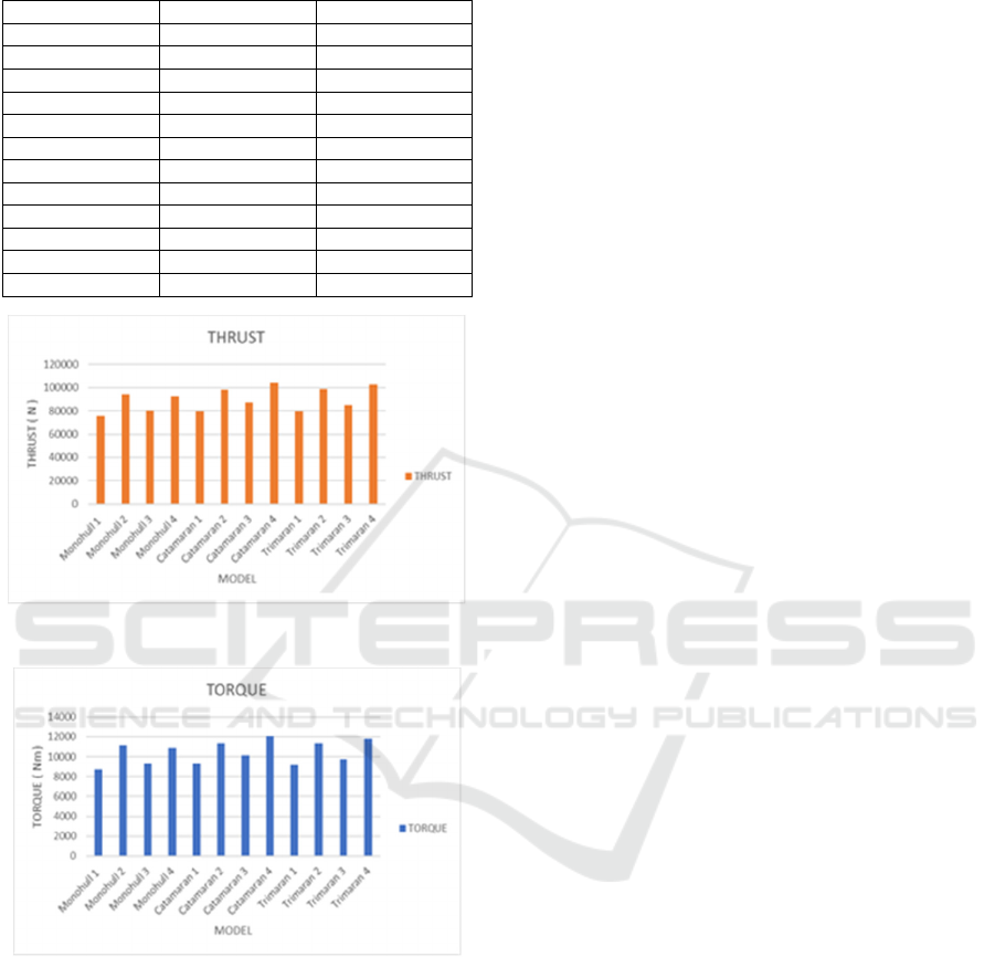
Table 5: Result of Thrust, Torque, and Efficiency of 16
Variation Propeller Model.
Model Thrust (N) Torque (Nm)
Monohull 1 75706 8745,81
Monohull 2 94624 11171,7
Monohull 3 80239 9300,41
Monohull 4 92666,6 10894,8
Catamaran1 79483 9267,26
Catamaran2 98143,9 11370,1
Catamaran3 87012 10136,2
Catamaran4 104105 12062,7
Trimaran1 79307,1 9193,42
Trimaran2 99067,6 11338,3
Trimaran3 84823,1 9771,13
Trimaran 4 102802 11779,4
Figure 20: Diagram of Thrust Propeller Value.
Figure 21: Diagram of Torque Propeller value.
3.5 Discussion
Based on the data in Table 5 and the Graphs in
Figures 20 and 21 show that the largest Thrust Value
for monohull vessels is obtained from the monohull
2 model, namely 70 Series K4 propellers that have
thrust of 94624 N.
The lowest Torque value for monohull vessels is
obtained from monohull 1 model, namely 70 Series
B4 propeller which has a torque of 8745.81 Nm.
The biggest Thrust value for Catamaran ships is
obtained from Catamaran 4 model, namely 70 Series
K5 propellers that have a thrust of 104105 N.
The lowest Torque value for Catamaran ships is
obtained from the Catamaran 1 model, namely the
70 Series B4 propeller which has a torque of
9267.26 Nm.
The biggest Thrust value for Trimaran ships is
obtained from Trimaran 4 models, namely 70 Series
K5 propellers which have a thrust of 102802 N.
The lowest Torque value for Trimaran ships is
obtained from the Trimaran 1 model, namely the 70
Series B4 propeller which has a torque of 9193.42
Nm.
Based on table 5 shows that the increasing
number of blade in the variations carried out will
increase thrust propeller. The greater the value of
Rpm or propeller rotation, the greater thrust will
result.
4 CONCLUSION
Based on the results of the calculation and
computational fluid dynamic simulation are
obtained, that is:
1. The Monohull 2 model, the K4 70 Series
propeller can be used as an alternative choice for
monohull ship propellers because it has
maximum thrust value.
2. Catamaran 4 model and Trimaran 4, K5 70
Series propeller can be used as an alternative
choice for Catamaran and Trimaran ship
propellers because they have maximum thrust
value.
REFERENCES
A. Trimulyono, 2015. Analisa Efisiensi Propeller B-Series
dan Kaplan Pada Kapal TugBoat ARI 400 HP Dengan
Variasi Junlah Daun , KAPAL, vol. 12, pp. 112–120.
G. P. Wibowo, D. Chrismianto, 2017. D. T. Perkapalan,
and U. Diponegoro, Analisa Nilai Thrust Optimum
Propeller B4-70, KA4-70 dan AU4-59 Pada Kapal
Tugboat Pelabuhan Paket-II 2X1850HP Dengan
Variasi Sudut Rake Menggunakan CFD, J. Tek.
Perkapalan, vol. 5, no. 1, pp. 27–37.
H. Nurul, 2013. Analisa Pengaruh Energy Saving Device
Pada Propeller Dengan Metode CFD. Semarang:
Tugas Akhir, Jurusan Teknik Perkapalan, UNDIP.
Hartono, 2008. Design Ekonomis Untuk Propeller Kapal,
TEKNIK, vol. 29, no. 3.
M. M. Bernitsas, 1981. KT, KQ and Efficiency Curves for
the Wageningen B-Series Propeller, Michigan.
Thrust Analysis and Type of Kaplan Series and B Series Torque Propeller on Monohull, Catamaran, and Trimaran Vessels with Variations in
Number of Blade using Computational Fluid Dynamic
27

P. Bangkit, S. Budi, D. Chrismianto, and G. Rindo, 2016.
Analisa Performance Propeller Tipe B-Series pada
Kapal Selam Midget 150M Dengan Variasi Skew
Angle dan Blade are Ratio (AE/AO) Menggunakan
Metode CFD, J. Tek. Perkapalan, vol. 4, no. 4, pp.
725–737.
Y. Rahardian Andilolo, 2017. Studi Kasus Kinerja
Propeller Kaplan Series Akibat Pengurangan Diameter
dan Penambahan End Plate dengan Metode CFD, J.
Tek. Perkapalan, vol. 5, no. 1, pp. 205–213.
ISOCEEN 2018 - 6th International Seminar on Ocean and Coastal Engineering, Environmental and Natural Disaster Management
28
