
The Stamping Springback Compensation Technology Study for An
Auto B Pillar
Guanglin Shi
1
, Jinhai Cheng
1
, Shaowen Lv
1
and Xuezhao Zhou
1
1
Institute of Mechanical Engineering, Guangxi University of Science and Technology,
Chengzhong District, Liuzhou City, China
Keywords: Spring back Compensation; CAE simulation; Reverse Engineering .
Abstract: The stamping spring back problem of a sheet metal is always a difficult point to solve in production, and it
also becomes a hot issue in academic circle. This paper introduced a method to reduce the springback
deformation of an auto B pillar. A Handy Scanner was used to acquire the points cloud datum of a drawn B
pillar; afterwards, all surfaces of this part were reconstructed in the Geomagic Studio software, taking
advantage of this datum. Consequently, the dimension difference between the reconstruction and primitive
numerical model was obtained by using the Geomagic Qualify Probe software, and it was the springback
value of this auto B pillar after drawn. To reduce the springback value of this part, according to the positions
presenting springback maximum, some offset dimensions on stamping die surfaces were compensated.
Finally, DYNAFORM software was used to simulate the forming process with the improved die, to analyse
the improved springback results of this part. The result shows this method is effective to reduce springback.
1 INTRODUCTION
The forming precision is an important indicator to
the qualification of a stamping part, and it is badly
influenced by the spring back problem. In realistic
stamping production, the spring back of a sheet
metal is always difficult to predict and solve. To
reduce the spring back of a sheet metal, many
researchers have been doing a great deal of work.
Luc Papeleux, Jean- Philippe Ponthot[1] detailedly
studied several parameters’ influence on spring back
with FEA method, including BHF(blank holder
force), friction, spatial integration, time integration
scheme and constitutive laws, using a 2D U-draw
bending case. Michael Krinniger, Daniel Opritescu[2]
et al. studied the influence to the springback
behaviour with different bending parameters, punch
velocity and materials by some experimental
investigation, and they developed an extendable
metal model, then they advised that we should
consider these factors’ influence to spring back in
the design process, so that we obtained a sheet metal
with enough dimensional accuracy. L. Komgrit, H.
Hamasaki[3] et al. introduced a new technology to
eliminate spring back, they pushed up the bottom of
the sheet metal with a counter punch, and they
testified their method by experiment and simulation;
H. Naceur, Y.Q. Guo[4] et al. introduced a method
in order to reduce the springback effects by
optimizing the geometry of tools in sheet metal
forming, they made optimized design to tools’ radii,
thickness distribution and material parameters
according to a new response surface method and
their experiment. Finally, they validated their results
by using STAMPACK and ABQUS software.
With the progression of science and technology,
nowadays we can use Reverse Engineering to
acquire exact difference between the end product
and primitive numerical model, and we also can use
CAE technology to simulate stamping process, and
analyse the springback of an end product. These new
techniques break a new path to solve this problem.
The B pillar is a main part supporting a car’s
body structure, meanwhile, it bearing the pressure
from the front door and rear door, so it must has
sufficient strength and stiffness. The B pillar has a
complicated surface construction, it’s manufacturing
processes including drawing, triming, reshaping and
punching, among which the drawing process has an
important influence on its’ final forming precision.
Aiming at a whole car having more light weight, this
B pillar was made of high strength steel, which
allowed much less thickness to ensure sufficient
mehcanical properties, and in this case the thickness
of part was 1mm. The parameters of the material of
this B pillar was illustrated as follow table:
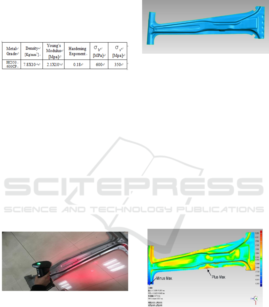
Table 1: Mechanical Properties of Material.
2 SPRINGBACK DETECTION
2.1 Part Drawn Numerical Modelling
After the B pillar was manufactured in drawing
process, a stamping springback would occur in some
locals of this part. Springback is an inevitable
phenomenon in forming process, and it directly
influences dimensional precision and final shape of a
sheet metal [5]. Springback causes difference in
dimension between the final product and the
primitive numerical model designed by engineer. To
acquire this difference value, we can use Reverse
Engineering Technology. Handy Scanner is a device
which is in common use in optical scanning field. In
this study case, we used a handy scanner whose type
was Handy Scan 700, its resolution ratio running up
to 0.05mm, and maximum precision was 0.030mm.
After some adjusting and pre-processing work was
done, we used this instrument to scan the drawn part.
Our site work was shown as follow:
Figure 1: Using Handy Scan 700 to scan a drawn part.
Then we used this points cloud datum acquired
from Handy Scan 700 to reconstruct a numerical
geometric model of the drawn B pillar in the reverse
modelling software, Geomagic Studio. The
following drawing was the reconstructed model.
Figure 2: The reconstructed model of a drawn part.
2.2 Springback Detection
In this section, we used the Geomagic Qualify Probe
software, to detect the difference between the drawn
model and the primitive numerical model. Inputting
the both numerical models into this software, the
primitive model as reference model and the
reconstructed model as test model, aligning these
two models, clicking 3D contrasting menu, we can
obtain the difference value in dimension as the
following figure.
From this figure, we can observe the maximum
differences was +3.64mm and minimum -5.21mm,
representing the springback values were 3.64mm
and 5.21mm on the local positions, and Geomagic
Qulify Probe already marked the positions by two
highlight points. Additionally, we also can see most
of the difference values be from -1.91mm to
1.91mm, the average dimensional difference of these
two models was ±0.66mm, and the standard
deviation was 0.87mm, so these deviations were
acceptable in general. The next work was to reduce
the oversize deviations by some means.
Figure 3: Springback value contour.
3 SPRINGBACK
COMPENSATION
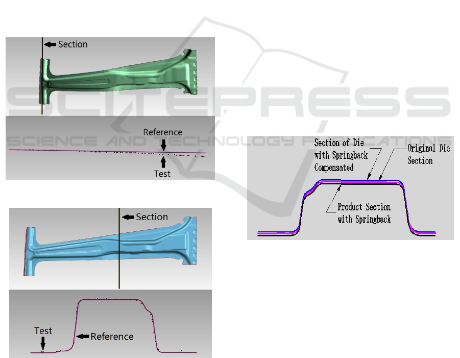
3.1 Springback Value Quantization
Using Geomagic Qualify Probe to make some
sections crossing the local positions in which the
maximum springback and oversize springback were
located, we got some section boundary lines from
the reference model, and some points around these
lines from the test model. Along each of these
section boundary lines we selected some reference
points from the test model, then projecting these
points to the section line along the line’s normal
direction, we can obtain the crossover points on the
section boundary lines; dimensioning the distance
from each point to the opposite crossover point, we
can obtain the springback value of each point on the
primitive geometry model designed by engineer. The
springback plus maximum and minus maximum
sections were shown by the following graph:
Figure 4: Springback plus maximum section.
Figure 5: Springback minus maximum section.
3.2 Die Profile Compensation
From the above several chapters, we already
obtained the actual precise difference values in
dimension between the primitive geometry model
and the drawn model, to compensate these
difference values, in this paper we adopted one
method which changed the molded surfaces of the
die and punch. According to the springback value of
each point, we changed these points position to the
reverse side of the section boundary, in other words,
we giving two times of difference value along the
normal direction of the section line to compensate
springback value. Based the original model and
these changed points, we can generate a new model
whose surfaces were renewed with springback
compensated points, and this model constituted the
new die. By using the CATIA software, inputting
the original model and carrying out the same
operations, assigning the original model as the entity
to be changed, selecting the generated line from
those compensated points as target entities, on
condition that all curves were continuous by its’
tangents, taking advantage of the function of CATIA
which reconstructs surfaces from fitting NURBS
curves, subsequently, we got the new die whose
surfaces can offset the springback.
The section boundary lines cut from primitive
model and compensated model were compared as
following graph:
Figure 6: Die profile reconstructed with Springback
compensation by CATIA software.
4 COMPENSATION EFFCT TEST
4.1 Simulation Model Establishment
We had obtained the compensated die model in
CATIA, and the next work was to test whether our
improvement to the die was effective, and whether
the springback of the B pillar drawn from a drawing
die was reduced to meet our expectation. All these
work would done in the DYNAFORM software,
which took a simulation to the forming process.
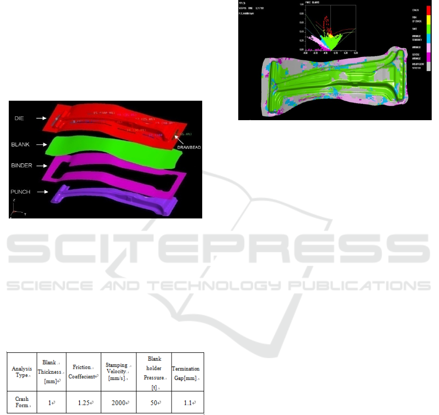
In CATIA, we saved the compensated die
surface as *.igs format, inputting this *.igs file to the
software DYNAFORM, off seting this shell model
with a distance equal to the thickness of a blank, so
we got the punch shell model; meanwhile we
extracted surfaces from the blank and blank holder
in their primitive solid structures to save as *.igs
format files, also inputting these files to
DYNAFORM as the blank and blank holder shell
models, meshing and positioning these shell models
including die, punch, blank, blank holder, the
established models in DYNAFORM as following :
Figure 7: Dynaform simulation models.
4.2 Forming Simulation
4.2.1 Simulation Process Parameters
According to the practical condition, we set some
process parameters in drawing simulation process as
following table:
Table 2: Simulation Process Parameters.
4.2.2 Simulation Results
After simulation completed, we used the
postprocessor module of DYNAFORM to open
*.d3plot file generated to observe forming results.
The following figure was the FLD (Forming Limit
Diagram) of the B pillar, and from this FLD we can
see the forming properties be good in general, there
being no crack and serve wrinkle happened on the B
pillar surface, most of its surface being in sufficient
drawing state, a small quantity of crack which
happened on the border of this B pillar would be
trimmed in later process, having no influence to the
whole forming quality. In brief, the whole forming
was well distributed, and the drawing process was
qualified.
Figure 8: FLD of the B pillar drawing simulation.
4.3 Springback Analysis Based on Die
Dimension Compensated
The purpose of all work above was to decrease the
springback of the B pillar by changing die molded
surface, and whether our purpose would achieve can
be confirmed though using springback analysis
module in DYNAFORM software. Dynaform
simulates forming process with dynamic explicit
algorithm and calculates springback process with
static implicit algorithm, ensuring calculating
efficiency in simulation and calculating precision in
springback analysis [6]. Inputting the *.dynain file
generated with drawing simulation above to
DYNAFORM, after setting all parameters related
with analysis, submitting mission to solver to
calculate. After DYNAFORM solver finished this
mission, we can open *.d3plot file to see analysis
results in DYNAFORM postprocessor. The results
contained two frames *.d3plot files, one was the
starting model and the other was the model with
springback. Exporting each frame result file, we
obtained numerical model of each frame. The
springback was the difference between the starting
model and the springback model. We also used
Geomagic Qualify Probe to compare the different
value between the two models. The springback
results which located the springback maximum and
minimum positions were displayed with highlighted
points as following figure. The difference values
were displayed in the meanwhile.
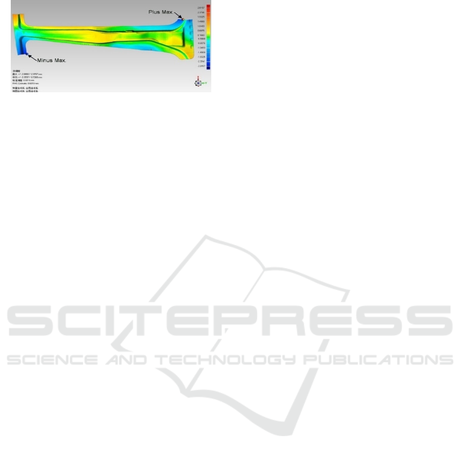
Figure 9: Springback of a B pillar stamped by an
improved die.
From this figure above, we can recognize the
maximum springback value was +2.09mm and the
minimum was -2.82mm, which were largely reduced,
compared with the original springback values which
were +3.64mm and -5.21mm. Additionally, we also
can see most of the difference values locate in the
interval from -1.05mm to 1.05mm, the average
dimensional difference of these two models was
changed to be ±0.53mm, and the standard deviation
was 0.60mm; That was to say, all deviations were
reduced in some extent, so the analysis results
supported our improving work to be effective.
5 CONCLUSIONS
Taking a comprehensive survey on our whole work
in this paper, we introduced a systematic method to
reduce springback of a car B pillar, and we used
optical scanner, HandyScan 700, to obtain points
datum of a drawn B pillar, contrasting difference
between the points datum and primitive model in
Geomagic Qualify Probe to obtain springback values;
According to these springback values, we changed
die surface with a compensation value in CATIA;
Afterwards, we used DYNAFORM to simulate the
drawing process with the reconstructed die model,
and analysed the springback of the B pillar which
stamped with new die and punch whose surfaces
were compensated. The results confirmed that our
improving work to die was effective. This method
solves the problem which is difficult to predict and
measure the springback of a final sheet metal, so it
can be valuable in some engineering projects.
Because of the springback phenomenon, the
dimensional precision of a car B pillar is very
difficult to ensure; To obtain a qualified B pillar, the
traditional method to debug press tools mainly
depends on the experience of a bench worker. In that
case, the workload of the worker is very heavy;
moreover, it takes the worker enormous amount of
time to find where the press tools must be modified,
so that the traditional method lengthens the cycle of
press tools’ development and manufacturing. By
using our method introduced in this paper, we can
accurately find where the press tools should be
modified with a high efficiency, so it can shorten
press tools debugging cycle; Besides this, as the case
mentioned in this paper, we decreased the average
deviation value of the B pillar from 0.66mm to
0.53mm, so the results also satisfied us, thus it can
enhance the forming qualification and precision of a
sheet metal.
ACKNOWLEDGEMENTS
The authors gratefully acknowledge the financial
support of Guangxi Education Department Project
for Science and Technology, under project The
Precision Control Method Study for Whole Life
Cycle of a Die with reference KY2015ZL125.
REFERENCES
1. Luc Papeleux, Jean-Philippe Ponthot , Journal of
Materials Processing Technology, 2002. Finite
element simulation of springback in sheet metal
forming. 125-126(2002) 785-791.
2. Michael Krinninger, Daniel Opritescu, Roland Golle,
Wolfram Volk. 48
th
CIRP Conference on
MANUFACTURING SYSTEMS, 2016, Experimental
investigation of the influence of punch velocity on
springback behavior and the flat length in free
bending. Procedia CIRP 41(2016) 1066-1071
3. L. Komgrit, H. Hamasaki, R. Hino, F. Yoshida ,
Journal of Materials Processing Technology, 2016.
Elimination of springback of high-strength steel sheet
by using additional bending with counter punch.
Volume 229, Pages 199-206.
4. H. Naceur, Y.Q. Guo, S. Ben-Elechi, Journal of
Computers & Structures, 2006. Response surface
methodology for design of sheet forming parameters
to control springback effects. Volume 84, Issues26-27,
October 2006,Pages 1651-1663.
5. Cheng chen, Hu Jianhua, Shang Huishen, Li Ming.
Journal of Hot Working Technology, 2011.
Springback in Sheet Metal Stamping and Its Solutions.
Volume 40, Issues11, Pages 194-197.
6. Su Chunjian, Yu Tao, 2011. Book of CAE Analysis
and Application in Sheet Metal Forming, National
Defense Industry Press, China. 1
st
edition.
