
Researches on a Wall-Climbing
R
obot Based on Electromagnetic
Adsorption
Kai Huang
1
, Xiangdong Li
1
, Ye
Sun
2 b
, Yong Chen
2 a
, Miao Hao
2
and Yihui Zhang
1
1
Special Equipment Safety Supervision Inspection Institute of Jiangsu Province, Nanjing 210036, China
2
Nanjing Forestry University, Nanjing 210037, China
Keywords: Wall-climbing robot, electromagnetic absorption, embedded control.
Abstract: The technical bottleneck of the wall-climbing robots based on magnetic adsorption is that the magnetic
force is not only the adsorption force but also the moving resistance force. The bigger the adsorption force
is, the bigger the moving resistance force is. In order to solve this problem, a unique wall-climbing robot
based on electromagnetic adsorption is proposed. Electromagnets fixed in the synchronous belts get into or
out of work in turn to realize the unity of adsorption and mobility. An embedded Linux system is
constructed to transport videos from the robot to the handheld terminal in real time. A MCS-51 based
controller is designed to perform robot control. A prototype robot is manufactured and tested. Experiments
show the video delay is less 0.45s and the remote-control distance is beyond 80m.
1 INTRODUCTION
Wall-climbing robots have wide applications in
industry and other fields. According to serving
environment and working media, the adsorption
modes for wall-climbing robots are classified into
negative pressure adsorption[1-2], bionic dry
adhesive adsorption[3-4], magnetic adsorption and
etc. Negative pressure adsorption is not limited by
working media, but it will suffer from air leakage if
the surface is very rough. Bionic dry adhesive
adsorption is suitable for all kind of surfaces, and
magnetic adsorption only works for magnetic-
conductor. Magnetic adsorption includes
electromagnetic adsorption, permanent magnetic
adsorption and their combinations. As to magnetic
adsorption, many researches are focused on
permanent magnetic adsorption[5-8]. A few of
researches are based on electromagnetic
adsorption[9]. Extensive researches have been
carried on wall-climbing robots for many years, but
there is few prototype wall-climbing robot which is
suitable for actual uses until now. One of the
technical bottlenecks is the unity of adsorption and
mobility.
2 OVERALL DESIGN
In this paper, a unique structure is proposed to solve
the above problems. As shown in Figure 1, the
unique wall-climbing robot is composed of a main
frame, two synchronous belts with embedded
electromagnets, two conductive troughs, four
synchronous belt wheels, two step motors and its
controllers, and etc. The conductive plate provides
electric power for the electromagnet. 16
electromagnets are fixed in a synchronous belt
equispacedly. The U-shaped conductive trough is
arranged inside the synchronous belt. When the
synchronous belt wheels are driven to rotate, the
electromagnets will be brought into and out of
contact with the conductive trough one by one. That
is, only these electromagnets which contact with the
conductive trough can generate magnetic force. In
this way, when the wall-climbing robot moves
forward, the electromagnets will get into or out of
work in turn. As to our prototype, 6 electromagnets
always stick to the wall surface at the same time to
support the whole robot. According to this scheme,
the magnetic force is only the adsorption force
instead of the resistance force.
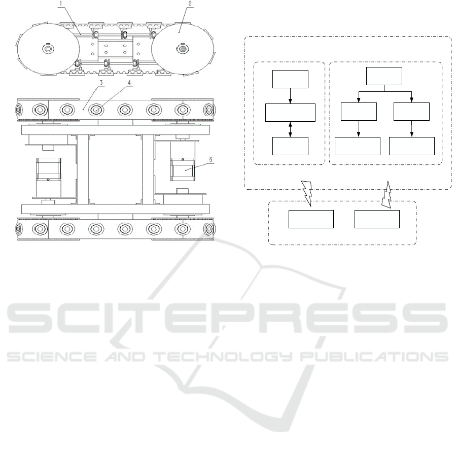
Figure 1: The plane assembly drawing of wall-climbing
robot
1-Conductive plate, 2-Timing belt pulley,3-Timing belt, 4-
Electromagnet, 5-Stepper motor
In addition, the main frame is made of
aluminium alloy in order to reduce the weight. The
robot outline is 335mm*295mm, and the wheel is
106mm in diameter. A camera on the robot is
employed to capture videos and the operator can
watch the pictures displayed on the screen of a
handheld terminal.
In this paper, comprehensive consideration of
different forms of controls, the control system of the
wall-climbing robot uses two distributed control
systems which are hand-hold terminal control and
vehicle on-board controller. Figure 2 shows the
overall block diagram of derusting wall-climbing
robot.
The main function of the wall-climbing robot’s
hand-hold terminal is to send the control signal to
the vehicle-mounted controller by wireless
transmission so as to realize the remote-controlled
movement of the wall-climbing robot.
The on-board controller is the execution layer of
the wall-climbing robot control system. It has two
main functions: one is to control the climbing robot's
forward, backward and steering on the wall, and the
other is to communicate with the handheld terminal
by wireless communication. The microcontroller
board of vehicle controller will immediately execute
the appropriate procedures to control the stepper
motor after receiving the command signal, and then
it can control the movement of the wall-climbing
robot.
Microcontroller
Left driver
Right driver
Left stepper motor Right stepper motor
Wireless
Router
Network video server
UVC camera
Video capture and
transmission
Vehicle On-Board
Controller
Wall-climbing robot
Video display Instruction transfer
Hand-held Terminal
Wireless communication
Figure 2: Block diagram of control system of derusting
wall-climbing robot
3 DESIGN OF THE CONTROL
SYSTEM
3.1 Hardware Design
The handheld terminal is based on a MCS-
51controller to realize remote-control and image
wireless transmission. The circuit of the vehicle
control system is composed of STC12C5A60S2
microcontroller, stepper motor drive circuit, wireless
receiving circuit, power conversion circuit and serial
port download circuit. The wireless receiving circuit
is responsible for constantly receiving the control
instructions issued by the handheld terminal. After
receiving the control signal, it is resolved by the
single chip microcomputer as the output of the pulse
command to the stepper motor driver.
3.2 Software Design
One can operate the robot movement through the
interface of the handheld terminal. The software of
the vehicle controller includes wireless transmission
and stepper motor driving. The wireless reception
subroutine is for receiving control instructions
issued by handheld terminal. Figure 3 shows the
flow chart of receiving and sending subroutines.
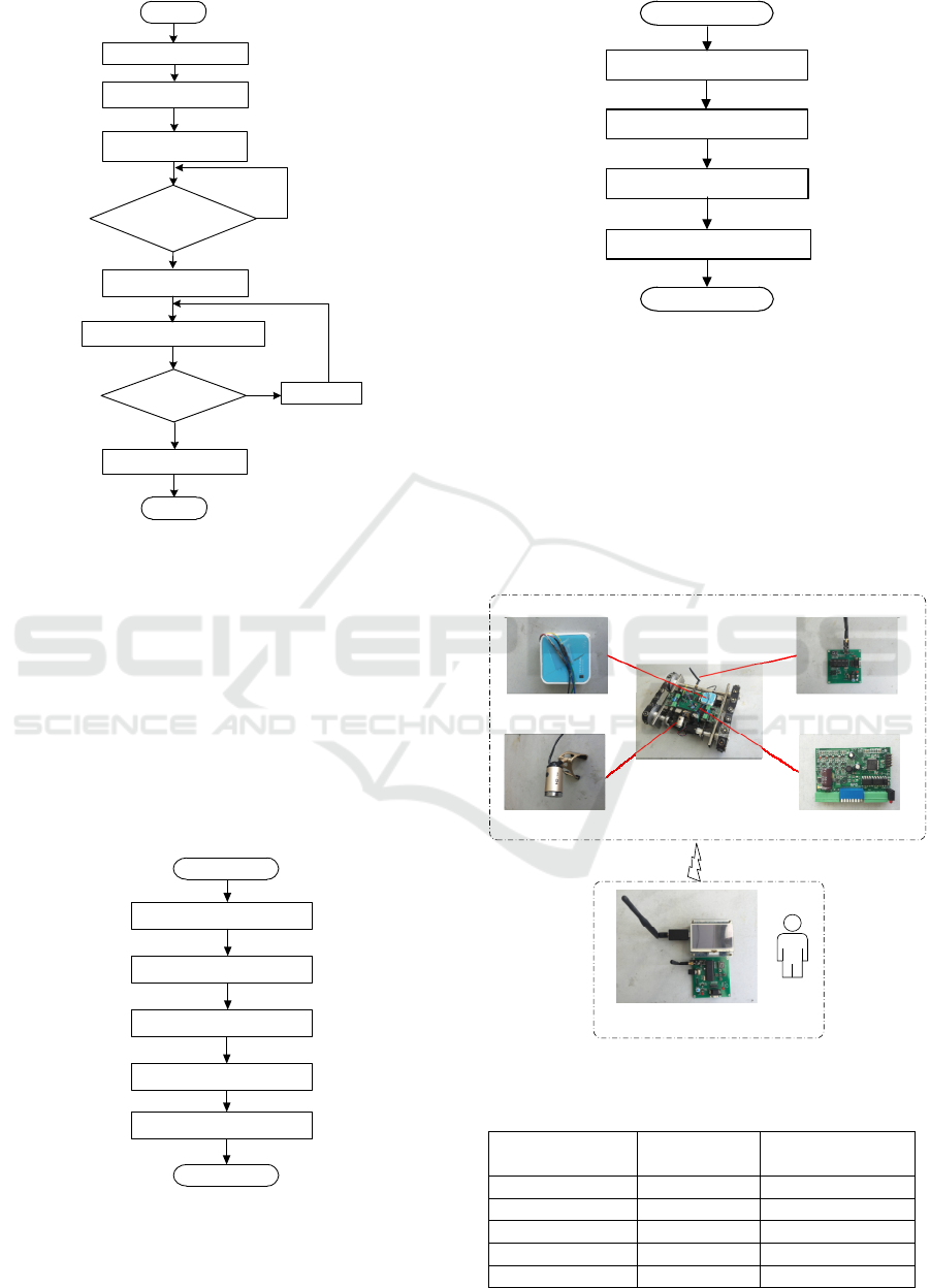
Initialize
NRF24L01
Set the sending/receiving mode to
send a reply signal
Start
Open the receive/send
interruption?
End
Yes
No
Configure to receive/send
mode
Answer completed?
Yes
No
Configure the module to
receive/send mode
Receive/send data packets
into the stack
Receive/send data
Aut o an swer
Figure 3: Subroutine for Wireless receiver/ transmission
4 WIRELESS IMAGE
TRANSMISSION
Images captured by a camera on the robot are
displayed on a screen mounted on the handheld
terminal. The hardware needed for wireless video
transmission is composed of an embedded
development board, a router and a camera. The
software development processes are shown in Figure
4 and Figure 5.
Cross compilation environment
construction
Transplantation of Bootloader
Transplantation of Linux kernel
The construction of the root file
system
Transplantation of wireless
network card driver
End
Start
Figure 4: The steps of building the software development
environment of Linux system
Transformation of wireless
router
Building of MJPG-streamer
video server
Installation of UVC camera
driver
Transmission of video data
End
Start
Figure 5: Building of video image acquisition end
5 RESULTS AND CONCLUSION
A prototype robot was designed and manufactured,
as show in Figure 6. Experiment results on video
transmission are shown in Table 1. The max video
delay is about 0.45s. Since the robot moves slowly
in routine inspection, the delay is acceptable in our
application.
Router
Camera
Wall-climbing Robot
Vehicle On-Board Controller
Stepper motor drive
Wireless communication
Hand-hold Terminal
Figure 6: Composition diagram of experimental system
Table 1: Main directory of root file system(unit:second)
Actual
stopwatch time
r
LCD display Delay
03:29.26 03:29.06 0.20
03:39.37 03:38.93 0.44
03:40.58 03:40.13 0.45
03:42.37 03:41.95 0.42
03:44.04 03:43.75 0.29

ACKNOWLEDGEMENTS
Thanks for the following supports for our
researches: General Administration of Quality
Supervision, Inspection and Quarantine of the
People's Republic of China (2017QK044), General
Administration of quality and Technology
Supervision of Jiangsu Province (KJ175915),
Special Equipment Safety Supervision Inspection
Institute of Jiangsu Province (KJ(Y)2016019).
REFERENCES
1. Zhang Zibo, Liu Rong, Yang Huixuan. Development
of a Climbing Robot for Glass-wall cleaning[J].
Automation & Instrument,2016,(5):6-9,28.
2. Dong Han, Cui Dengqi, Li Fangxing, and etc. Design
and analysis on a wall Climbing Robot with Frame
Body and Suction Discs[J]. Manufacturing
Automation,2016,38(6):59-63,69.
3. Ig Mo Koo, Tran Duc Trong, Yoon Haeng Lee, and
etc. Development of Wall Climbing Robot System by
using Impeller Type Adhesion Mechanism[J]. Journal
of Intelligent & Robotic Systems, 2013,72:57-72.
4. Keng Huat Koh, M. Sreekumar, S.G. Ponnambalam.
Hybrid Electrostatic and Elastomer Adhesion
Mechanism for Wall Climbing Robot[J].
Mechatronics,2016,35:122-135.
5. Cui Zongwei, Sun Zhenguo, Chen Qiang, and etc.
Wall Climbing Robot Based on Two-end Adsorption
for Weld Seam Amending[J].Robot, 2016, 38(1):122-
128.
6. Xu Zeliang, Ma Peisun, Gao Xueguan. Design of the
Wall-climbing Robot's Tracked Sucker Based on
Multi-Body Magnetic Gradual Alternate
System[J].Journal of Shanghai Jiaotong University,
2002, 36(10):1488-1491.
7. Yi Zhengyao, Gong Yongjun, Wang Zuwen, and etc.
Wall-attachment Model and Its Simulation on a New
Wall-climbing Robot for Rust Removal[J].Journal of
Sichuan University (Engineering Science Edition),
2011, 43(2):211-216.
8. Wen Jing, Dun Xiangming, Miao Songhua, and etc.
Structure Design and Weld Seam Surmounting
Characteristic of a Wall-climbing Robot with Variable
Magnetic Adsorption Force Device[J].Robot, 2011,
33(4):405-410,501.
9. Li fan. Researches on the key techniques of a wall-
climbing robot for crane surface fault detection at
harbors[D]. Nanjing: Nanjing Forestry
University,2017.
APPENDIX
Hong Xiaowei,the student of Nanjing Forestry
University, is the co-author of this article.
