
Numerical Simulation of Welding Deformation and Flame
Straightening of Ear Plate Structure
Liping Zhang
1
, Ang Ji
1
, Guo Ma
2
, Changyu Lu
3
and Xiaohong Zhan
4
1
XCMG Research Institute. Ltd, Xu Zhou, China
2
State Key Laboratory of Intelligent Manufacturing of Advanced Construction Machinery, Xu Zhou, China
3
XCMG Environment Technology. Ltd, Xu Zhou, China
4
Nanjing University of Aeronautics and Astronautics, Nan Jing, China
Keywords: Ear plate structure, welding deformation, flame straightening, DOE
Abstract: In this thesis, the simulation model of welding and flame straightening process based on the Thermal
elastic-plastic method is developed by taking the ear plate structure as object of study. The primary and
secondary relations of straightening effect influenced by heating temperature, heating width and heating
time are analyzed through DOE procedure. The results show that: The parameters of flame straightening are
dependent on each other, and the heating width has the greatest influence on deformation straightening;
When the heating temperature is 750℃, the heating time is 20±2 s and the heating width is 30 mm, the
distance between two ear plates is 130.5 mm, which satisfies the design requirement reasonably.
1 INTRODUCTION
Due to the advantages of simple production process,
short manufacturing cycle and high flexibility of
structure design, welding has become found amental
processing method of complex construction.
Nevertheless, welding residual strain resulting from
uneven temperature field should not be ignored on
account of the extremely complex special
characteristics of high temperature, dynamicity and
transience in welding process. Hence deformation
straightening process should be added after welding
procedure so as to avoid structural geometrical
imperfection and instability of product quality
caused by welding deformation[1,2].
As a distortion rectification method used widely
at home and abroad, flame straightening is utilized
to rectify the welding deformation through heating
plate locally based on the thermal expansion theory
of metallic materials using a simple equipment,
which is suitable to the straightening of large
welding products typically. However, the
straightening effect is affected by the operator's
experience including various factors such as heating
temperature, heating time, heating area and heating
position, which increase the uncertainty of the
straightening effect. The process of flame
straightening has been studied in detail by a lot of
researchers[3,4]. Zhang Yujuananalyzed the
microstructure and mechanical properties of S355J2
structure steel after the correction process[5]. Zhu
Zhaohua expounded the factors to be taken into
consideration in flame straightening and welding
deformation[6]. ZengXiaopeng discussed the usage
of inherent strain method in simulation of flame
correction[7]. K B Jayananalyzed the flame
straightening process of Corrosion Resistant
Structural Steel. Based on the experimental results,
the study revealed the consequences of flame
straightening on microstructure and mechanical
properties of the work material influenced by oxy
acetylene pressure, torch nozzle diameter and the
holding time[8]. Zhao Dongsheng proposed a
formula for selection of gas flow based on
‘straightening energy input = welding energy input’,
which was verified reasonable by test results[9].
Juan Blandon compared three different gas heating
methods commonly employed in actual practice and
judged which was more efficient in terms of
correcting welding distortion while reducing energy
and time consumption[10].
In this paper, welding deformation and flame
straightening process of ear plate are simulated in
FE software and DOE method is provided to analyze
the main factor of straightening effect in order to
supply effective guidance to the actual flame
straightening operation of ear plate structure.
2 PHYSICAL MODEL OF EAR
PLATE STRUCTURE
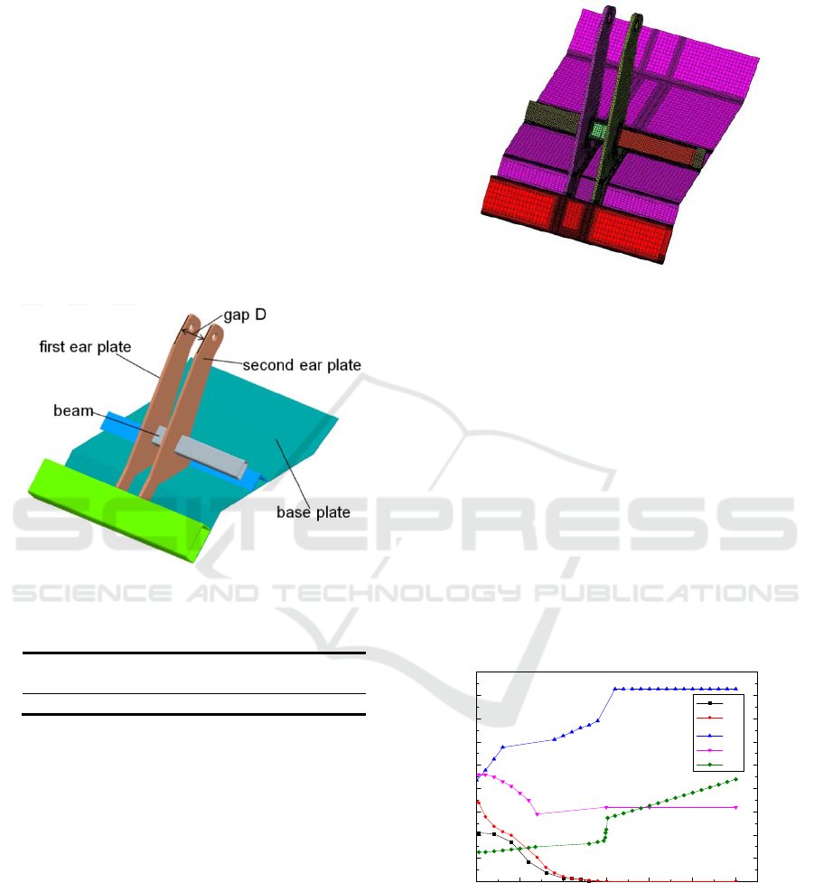
The overall geometrical model of the ear plate
structure is shown in Fig1, including base plate,
beam and two ear plates. The material of plates is
Q345 and the fillet joint is achieved in carbon
dioxide gas shielded welding with the Fronius
TPS5000 welding power. There is no welding
groove on the plate and the surface of specimen
would be cleaned before welding. The welding
process parameters are shown in Tab 1. The gap D
between two ear plates shall not meet the assembly
requirements of 131mm after welding, and the
welding deformation of the first ear plate should be
rectified by means of flame straightening.
Fig1:Geometrical model of ear plate.
Tab1:Welding process parameters.
name I /A U/V ν/(mmꞏs
-1
)
value 260~280 26~28 6
3 WELDING SIMULATION
MODEL OF EAR PLATE
3.1 Generation of Grid Model
The geometrical model of ear plate is partitioned
into solid grid model. The base mental is divided
into 2~3 layers in order to ensure the accuracy of
calculation and the size of grid around weld and
HAZ is set as 2mm so as to improve the calculation
speed, while the size of grid remote from the
welding zone is 6mm. Two element transitions are
adopted in the width direction among the above-
mentioned regions to ensure the accuracy of
calculation and reduce the number of elements. As
shown in Fig2, the element number of ear plate grid
model is 144956.
Fig2: Grid model of ear plate structure.
3.2 Relevant Parameters Setting of
Finite Element Model
Double ellipsoid thermal source is used as the
boundary condition of welding heat source due to
the temperature change of welding process is totally
involved during the welding process. The material of
ear plate grid model is set as Q345 and it is assumed
that the whole model has the same thermal physical
property parameters with the change of temperature.
The base metal and welding wire are set equipped
with isotropic properties: poisson's ratio is 0.33,
mass density is 7870 kg/m3, and the other
parameters such as thermal conductivity, specific
heat, elastic modulus, thermal expansion coefficient
with the temperature change are shown in Fig 3.
0 500 1000 1500 2000 2500 3000
0
1
2
3
4
5
6
7
8
9
0
1
2
3
4
5
6
7
8
9
αl×10
-5
/(mm/mm/C)
()
λ×10/(N/ s.C )
c×10
8
/(mm
2
/s
2
/K)
R
eL
×10
2
/MPa
E×10
5
/MPa
T/
℃
E
R
eL
c
λ
αl
Fig3: The relationship between heat-force parameters and
temperature of Q345.
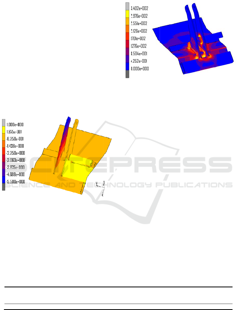
3.3 Welding Deformation Analysis of
Ear Plate Structure
The welding deformation of ear plate structure as
shown in Fig 4 is extracted after the calculation is
complet
e
cooled t
o
structur
e
material
’
results
i
zone
w
deforma
t
directio
n
sides w
h
up to -
5
input.T
h
of weldi
n
actual s
i
of ear pl
is show
n
achieve
d
340 MP
a
HAZ is
welding
Fig4:We
l
structure.
na
m
val
u
e
d when the
o
room temp
e
e
deformatio
n
’
s expansion
i
n some plas
w
hich would
t
ion of the
s
n
is only 0.1
m
h
ile the defor
m
5
.5mm as a
h
e gap D is al
n
g deformati
o
i
tuation.The
V
ate structure
a
n
in Fig5, fr
o
d
that the ma
x
a
and the wel
d
much high
e
zone which e
l
ding deform
a
m
e
Oxygen
p
/M
P
u
e 0.
7
ear plate st
r
e
rature.The
m
n
of ear plat
e
during the
tic distortio
n
retain afte
s
econd ear p
l
m
m due to h
e
m
ation of th
e
result of on
tered to 126.
2
o
n, which is c
V
ONMISES
a
fter the com
p
o
m which so
m
x
imum of VO
N
d
ing residual
s
e
r than that
ven close to
z
a
tion nephogr
a
p
ressure
P
a
p
7
r
ucture has
b
m
ain reason fo
r
e
is that the
b
welding pr
o
n
around wel
r welding.
l
ate along t
h
e
at input on
b
e
first ear pla
t
ly one side
2
5mm on acc
onsistent wit
h
stress nepho
g
p
letion of wel
m
e results ca
n
N
MISES stre
s
tress of wel
d
remote from
z
ero.
a
m of ear
Tab 2. Pa
r
acetylene
ressure(low)
/MPa
0.07
b
een
r
the
b
ase
o
cess
ding
The
h
e Y
b
oth
t
e is
heat
ount
h
the
g
ram
ding
n
be
ss is
d
and
the
plate
Fig
5
stru
4
4.
1
Th
e
sa
m
of
p
a
p
si
m
p
ar
a
ma
t
p
ro
si
m
inf
l
an
a
fun
de
fo
the
p
o
s
are
a
he
a
Th
e
r
ameters of fla
m
acety
l
p
ressur
e
/M
P
1.
1
5
:Welding res
i
cture.
FLAME
ANALY
S
STRUC
T
1
Finite
E
Flame
S
Structu
e
physical pr
o
m
e as that of
w
thermal, stru
c
p
er, the metho
m
ulation of fl
a
a
meters of
f
t
erial are set
cess. With
m
ulation as t
h
l
uence of w
a
lyzed during
w
ction would
fo
rmation and
welding
d
s
ition of flam
e
a
above the
b
a
ting method
e
parameters
o
m
e heating.
l
ene
e
(high)
P
a
a
c
1
i
dual stress
n
STRAIG
H
S
IS OF E
A
T
URE
E
lement M
o
S
trai
g
hteni
re
o
cess of fla
m
w
elding, both
c
ture and p
h
d of direct co
u
a
me straighte
n
f
inite eleme
n
in the sam
e
the result
o
h
e initial bo
u
elding on f
l
w
hich the “P
r
be used
t
residual stre
s
d
eformation
e
straighteni
n
b
eam in the
f
adopts the l
i
o
f flame heati
n
c
etylene gasflo
w
/m
3
•h
-1
2.25
n
ephogram of
H
TENIN
G
A
R PLAT
E
o
del Settin
g
n
g
of Ear
P
m
e straighteni
n
including the
h
ase transitio
n
u
pling is utili
z
n
ing, and th
e
n
t such as
m
e
way as th
e
o
f welding
n
u
ndary cond
i
l
ame straigh
t
r
evious Anal
y
t
o read the
s
s results. Ac
c
analysis res
u
n
g is located
a
first ear plat
e
i
near heatin
g
n
g are shown
w
nozzle di
a
/m
m
2.
5
ear plate
G
E
g
of
P
late
n
g is the
coupling
n
. In this
z
ed to the
e
r
elevant
m
esh and
e
welding
n
umerical
i
tion, the
t
ening is
y
sis State”
welding
c
ording to
u
lts, the
a
t the top
e
and the
g
method.
in Tab2.
a
mete
r
m
5
4.2 Design of Simulation Scheme
The effects of heating temperature, heating time and
heating width on the deformation were mainly taken
into consideration during the design of simulation
scheme and the three factors as well as
corresponding three levels are shown in Tab 3. The
experimental design of above-mentioned parameters
is carried out by the Latin hypercube method. As
shown in Tab 4, the experiment scheme is composed
of 10 samples and all of them are distributed evenly
in the sample place.
Tab 3: Distribution of heating factors and levels.
Temperature/℃
Time/s Width/mm
Level1 650
10±2
10
Level2 700
15±2
20
Level3 750
20±2
30
Tab 4:Test scheme and final results.
NO.
Temperature
/℃
Time
/s
Width
/mm
D
/mm
1 650
20±2
10 127.94
2 750
15±2
20 129.17
3 650
10±2
30 129.77
4 750
20±2
20 129.43
5 650
10±2
20 128.55
6 750
10±2
30 130.37
7 700
10±2
10 127.69
8 700
15±2
20 128.89
9 750
15±2
30 130.71
10 750
20±2
30 131.13
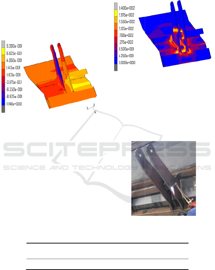
4.3 Thermal Deformation Analysis of
Flame Straightening of Ear Plate
Structure
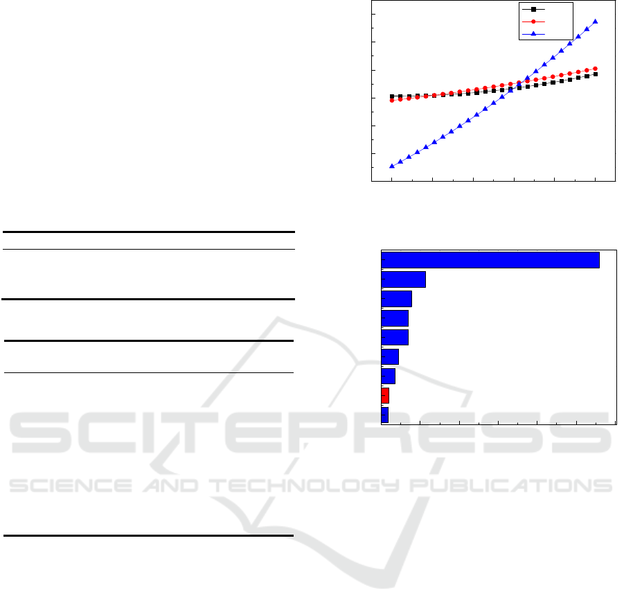
The simulation results of DOE are analyzed by the
main effect diagram and Plato after the calculation
completed so as to determine the effect of
parameters such as heating temperature, heating time
and heating width on the distance between two ear
plates.
1.0 1.2 1.4 1.6 1.8 2.0
127.5
128.0
128.5
129.0
129.5
130.0
130.5
distance /mm
level value
temp
time
width
Fig6:The main effect diagram of straightening parameters.
time^2
temp-time
temp-width
temp^2
time-width
width^2
temp
time
width
0 102030405060
% effect on distance
Fig7:The Plato of straightening parameters.
The main effect diagram of heating temperature,
heating time and heating width is shown in Fig6, as
can be seen from the figure, the heating width has
the largest influence on the gap D and the distance
changes dramatically with the change of heating
width, while the influence of heating temperature
and heating time are more gentle.
Fig7 shows the Plato of heating temperature,
heating time and heating width, and from the graph
it is evident that all of the parameters have a positive
effect on the gap D, among which the heating width
has the most positive effect on ear plate spacing,
followed by heating temperature and heating time.
Besides, the secondary and interaction terms have
less influence on the gap D and the interactivity of
temperature and time is negative for the ear plate
spacing.
The result is shown in Tab 3 that the distance
between two ear plates is 131.13 mm when the
heating temperature is 750 ℃, the heating time is 20
s and the heated width is 30 mm. As shown in Fig 8,
the Y direction deformation cloud diagram of the ear
plate structure under the straightening parameter is
obtaine
d
amount
o
remains
Howeve
r
the def
o
deforma
t
larger d
u
Fig 8: T
h
p
late stru
c
The
structur
e
is show
n
achieve
d
340 MP
straight
e
that of
a
The VO
higher t
h
same a
r
VONMI
d
. It can be
o
f the second
0.1mm
b
ec
a
r
, as far as t
h
o
rmation at
u
t
ion at the to
p
u
e to the flam
e
h
e welding def
o
c
ture.
VONMISES
e
after the co
m
n
in Fig9, fr
o
d
that the ma
x
a and the w
e
e
ning area an
d
a
rea remote fr
NMISES str
e
h
an that of
s
r
ea from t
h
SES stress n
e
Req
u
D
131
found that
ear plate alo
n
a
use there i
s
h
e first ear p
l
u
pper part is
p
area above t
h
e
straightenin
g
o
rmation clou
d
stress nepho
g
m
pletion of fl
a
o
m which so
m
x
imum of VO
N
e
lding residu
a
d
HAZ is still
om the abov
e
e
ss in the str
a
s
tructure aft
e
h
e comparis
o
e
phogram.
Tab
5
u
irement
W
e
m
u
±1mm
1
2
the deform
a
n
g the Y dire
c
s
no heat i
n
l
ate is conce
r
small while
h
e beam is a
l
g
.
d
diagram of th
e
g
ram of ear
p
a
me straighte
n
m
e results ca
n
N
MISES stre
a
l stress of
w
much higher
e
-mentioned
z
a
ightening ar
e
e
r welding i
n
o
n between
5
: Different res
u
e
ldingsi
u
lation
We
l
ct
u
2
6.5mm 12
6
a
tion
c
tion
n
put.
r
ned,
the
l
ittle
e
ear
p
late
n
ing
n
be
ss is
w
eld,
than
z
one.
e
a is
n
the
two
Fig
stru
str
a
we
l
he
a
san
sa
m
tw
o
me
a
des
u
lts of gap D b
e
l
dinga
u
ality
flam
s
6
.3mm
1
9:The VON
M
cture.
According t
o
a
ightening pr
o
l
ding deform
a
a
ting tempera
t
d the heatin
g
m
ple is shown
o
ear plates is
a
sured gap
D
ign requirem
e
Fig10:T
h
e
tween two ear
e straightening
s
imulation
1
31.13mm
M
ISES stress
n
o
the analysis
o
cessing is
u
a
tion of ear
p
t
ure is 750℃,
g
width is
3
in figure 10
a
measured.
A
D
is 130.5
m
e
nts.
h
e rectified sa
m
plates.
flame strai
g
actua
l
130.5
m
n
ephogram of
of the DOE
u
tilized to r
e
p
late which s
e
the heating t
3
0 mm. The
a
nd the gap
D
A
s shown in
T
m
m, which
m
m
ple of ear plat
e
g
htening
l
ity
m
m
ear plate
results, a
e
ctify the
e
t as: the
ime is 20
rectified
D
between
T
ab 5, the
m
eets the
e
.

5 CONCLUSIONS
(1) The finite element model of the welding
deformation prediction of the ear plate structure is
established based on the thermal elastoplastic finite
element method and the predicted results of welding
deformation are consistent with the measured results.
(2)The flame straightening processing
parameters are analyzed and optimized through
DOE experimental analysis method. Parameters
which have positive effect on deformation
rectification are as follows: heating width, heating
time and heating temperature while their quadratic
terms have little influence on distances between two
ear plates.
(3) According to the analysis of DOE results, the
straightening processing is determined as: the
heating temperature is 750℃, the heating time is 20
±2s and the heating width is 30 mm. The verified
test results show that the gap D meets the design
requirements.
REFERENCES
1. Pinzon, C., Hasewaga, K., &Murakawa, H.
(2016). Artificial Neural Network Application for
Parameter Prediction of Heat Induced
Distortion. Trends in Applied Knowledge-Based
Systems and Data Science. Springer International
Publishing.
2. Pinzon, C., Hasewaga, K., &Murakawa, H.
(2016). Artificial Neural Network Application for
Parameter Prediction of Heat Induced
Distortion. Trends in Applied Knowledge-Based
Systems and Data Science. Springer International
Publishing.
3. Doynov, N., &Michailov, V. G. (2018). Distortion
analysis of heat spot straightening thin-walled welded
structures: part 1: formation of the plastic deformation
zone. International Journal of Advanced
Manufacturing Technology, 94(1-4), 1-10.
4. Lacalle, R., Álvarez, J. A., Ferreño, D., Portilla, J.,
Ruiz, E., & Arroyo, B., et al. (2013). Influence of the
flame straightening process on microstructural,
mechanical and fracture properties of s235 jr, s460 ml
and s690 ql structural steels. Experimental
Mechanics, 53(6), 893-909.
5. Zhang Yujuan (2013). Flame straightening and
analysis of microstructure and mechanical property on
S355J2 structure steel. Chang Chun: Jilin University.
6. Zhu Zhaohua, Huang Juhua, Zhang Tingfang et al.
(2009). Application of flame correction method in
steel structure. Welding Technology,38(5), 63
-
66
.
7. ZengXiaopeng, Xu Ying. (2012).The Numerical
Simulation of Flame Correction to Ship Hull Plate
Based on ABAQUS. Science Technology and
Engineering, 12(35), 9635-9639.
8. Jayan K B, Kumar J P. (2016). Experimental
Investigation on Flame Straightening of Corrosion
Resistant Structural Steel Sheet Used for Rolling
Stock.
9. ZHAO Dongsheng, HUANG Zhenyu, MIAO Tangjun.
(2016). Experimental Parameter Calculation of
Welding Deformation Correction by Flame
Straightening. DEStech Transactions on Materials
Science and Engineering, mmme.
10. Blandon J, Osawa N, Masanori S, et al. (2015).
Numerical Study on Heat Straightening Process for
Welding Distortion of a Stiffened Panel Structure.
