
CdSe@TiO
2
Hollow Spheres Photoanode for Quantum Dots
Sensitized Solar Cells
L B Yu
1
, Z Li
1,2,*
, L Feng
1,2
and H Song
1,2
1
College of Chemistry and Chemical Engineering, Hexi University, Zhangye City
734000, Gansu Province, People’s Republic of China
2
Key Laboratory of Hexi Corridor Resources Utilization of Gansu, Hexi University,
Zhangye City 734000, Gansu Province, People’s Republic of China
Corresponding author and e-mail: Z Li, lizhen_665@163.com
Abstract. TiO
2
hollow spheres (HS) with size around 200-300 n m were synthesized using
carbonaceous sphere as sacrificial template. CdSe quantum dots were deposited on to TiO
2
HS by hydrothermal process employing th ioglycollic acid (TGA) as linker molecu lar to fo rm
CdSe@TiO
2
HS photoanode for solar cell applicat ion. Based on CdSe@TiO
2
HS photoanode,
the photovoltaic performances of solar cells were tested and showed that a 24 h hydrothermal
process make CdSe@TiO
2
HS solar cells exh ibit a power conversion efficiency of 1.49%,
which is the best among the sample solar cells. Possible reason for the working princip le of
CdSe@TiO
2
HS solar cell was proposed according to experimental facts. Th is wo rk provides
a novel insight to design structure of photoanode for quantum dots sensitized solar cells.
1. Introduction
Quantum dots sensitized solar cells (QDSSCs) have become a focus of investigation due to several
advantages such as low fabrication cost, high theoretical power conversion efficiency, and multiple
excitons phenomenon [1, 2]. A typical QDSSCs consisted of a photoanode, polysulfide electrolyte
solution, and a counter electrode [3, 4]. The photoanode constructed based on QDs sensitized TiO
2
is
the most important component of QDSSCs, playing a key role for the light harvesting, charge
generation, and charge transport [5]. The TiO
2
nanoparticles with sized around 25 nm are most
commonly used in QDSSCs due to a high specific surface area for QDs loading. However, weak light
scattering ability make TiO
2
nanoparticles not a suitable candidate to enhance light harvesting
efficiency in visible light region. Because resonant scattering of light is predicted to happen when
particle size is comparable to the wavelength of incident light according to Mie theory [6]. In view of
these issues, fabrication of TiO
2
hollow spheres as photoanode materials are particular attractive for
QDSSCs due to its large interfacial surfaces and enhanced light harvesting efficiency caused by light
scattering and multiple times light reflection inside of hollow spheres [7, 8].
In this work, we explore the synthetic approach of TiO
2
hollow spheres (HS) using carbonaceous
spheres as template. Based on TiO
2
HS, CdSe quantum dots were sensitized onto TiO
2
to form
CdSe@TiO
2
HS photoanode for QDSSCs application. An acceptable power conversion efficiency of
1.49% for CdSe@TiO
2
HS solar cells proved that the TiO
2
hollow spheres have potential application
in design of QDSSCs.
Yu, L., Li, Z., Feng, L. and Song, H.
CdSe@TiO2 Hollow Spheres Photoanode for Quantum Dots Sensitized Solar Cells.
In Proceedings of the International Workshop on Materials, Chemistry and Engineering (IWMCE 2018), pages 513-518
ISBN: 978-989-758-346-9
Copyright © 2018 by SCITEPRESS – Science and Technology Publications, Lda. All rights reserved
513

2. Experimental
All reagents were purchased from Aladdin and were analytical reagent (AR) grade, which were used
directly without any further purification.
2.1. Fabrication of TiO
2
hollow sphere (HS) photoanode
The TiO
2
HS were synthesized using carbonaceous microspheres as template [9-11]. In a typical
synthesis route, the carbonaceous microspheres, which were obtained by hydrothermal process of
sucrose aqueous solution in Teflon-stainless autoclave at 180 °C for 8 h, were dispersed in the 1 M of
TiCl
4
aqueous solution under ultrasonic for 20 min. Then the suspension was aged for 6 h. After
aging, the suspension was filtered, washed and dried to get black powders. Subsequently, the black
powders were heated to 500 °C in a muffle furnace at the rate of 1 °C min
-1
, with holding of the
temperature at 500 °C for 3h. Finally, the resultant TiO
2
HS powders in white were acquired.
The TiO
2
HS powders, ethylcellulose, terpinol, and ethanol were mixed to form a viscous paste.
Then the paste was doctor-bladed onto the FTO glass (2.0×1.5 cm), and the active area was
controlled to be 0.25 cm
-2
. After drying in ambient, the products were annealed in muffle furnace at
500 °C for 1 h to eliminate the organic residuals.
2.2. Synthesis of CdSe@TiO HS photoanode
The decoration of CdSe quantum dots (QDs) onto TiO
2
HS was achieved by hydrothermal process
using TGA as linker molecular. Cd precursor solution was prepared by mixing 1.2 mmol of
Cd(NO
3
)
2
and 1.2 mmol of TGA in 25 mL deionized wate, and was tuned to transparent by addition
of NaOH solution (5 M) into the Cd-TGA solution. The 0.1 M of Na
2
SeSO
3
solution prepared by
refluxing Se powder and Na
2
SO
3
at 96 °C was used as Se precursors. 4.0 mL Se source was added to
the Cd-TGA reaction medium. Then the resultant solution was transferred to Teflon-lined stainless
autoclave in which the TiO
2
HS photoanode was previously placed. The sealed autoclave was placed
in an electric oven and maintained at 150 °C to form CdSe@TiO
2
HS photoanode. The products
obtained by hydrothermal time of 12 h, 24h, and 36 h were used to investigate the influence of
hydrothermal time on photovoltaic performance.
2.3. Solar cell assembly
Cu
2
S prepared by immersing in polysulfide solution containing 1 M sodium sulfide and 1M sulfur in
deionized water was employed as counter electrode for CdSe@TiO
2
HS solar cells.
For the photovoltaic applications, the prepared CdSe@TiO
2
HS photoanode and Cu
2
S counter
electrode were assembled in a fashion similar to sandwich. The space between the two electrodes was
filled with polysulfide consisted of 1M sodium sulfide and 1M sulfur aqueous solution.
2.4. Characterizations
We employed Quanta 450 FEG scanning electron microscopy (SEM) and Tecnai G2 F20
transmission electron microscope (TEM) to record morphology of the prepared products. For crystal
phase characterization, we used D/MAX-2400 X-ray diffractometer to analyse the crystalline nature
and structure of the samples.
With the assistant of Oriel I-V test station, we investigated the I-V performance of the solar cells.
A solar simulator was used to simulate sunlight illumination with intensity of 100 mW cm
-2
.
3. Results and discussion
The key to synthesize TiO
2
hollow spheres (HS) is how to get homogeneous size of carbonaceous
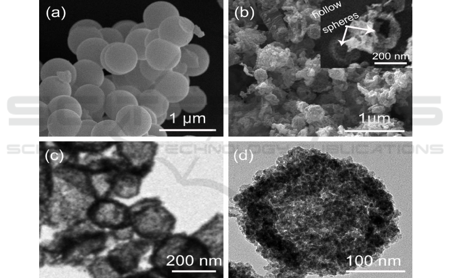
spheres. Figure 1 (a) shows the SEM image of carbonaceous spheres obtained by the hydrothermal
process of sucrose aqueous solution at 180 °C for 8 h. Apparently, the carbonaceous spheres with
size around of 500 nm can be successfully acquired after hydrothermal reaction, and the size
IWMCE 2018 - International Workshop on Materials, Chemistry and Engineering
514
distribution is uniform, providing potential application as templates for fabrication of hollow spheres
structure.
Based on these carbonaceous spheres, the TiO
2
hollow spheres (HS) are prepared. Figure 1 (b)
gives the SEM image of TiO
2
HS. The spherical structure could be identified, and the inset image
shows the broken hollow spheres which shell and empty inside can be observe.
The TEM of TiO
2
HS in Figure 1 (c) further give the fine structure of HS, the shell and empty
inside of the HS can be easily discerned in the TEM image, indicating the carbonaceous spheres
template method is an effective approach to obtain TiO
2
HS. As shown in Figure 1 (b) and (c), the
size distribution of TiO
2
HS is between 200 nm - 300 nm, which is smaller than that of original
carbonaceous spheres, indicating a shrinkage phenomenon occurred during annealing process in
muffle furnace. The surface area measurements show the BET of TiO
2
HS is around 21.6 m
2
g
-1
.
Figure 1 (d) displays TEM image of the CdSe@TiO
2
HS prepared by hydrothermal process with
TGA as linker molecular. Although the hollow sphere structure is still remaining, many small
particles have covered on the surface of TiO
2
HS, indicating the formation of CdSe@TiO
2
HS and
providing its potential application as photoanode in QDSSCs.
Figure 1. (a) the SEM of carbonaceous spheres; (b) the SEM of TiO
2
hollow spheres (HS), the inset
is SEM of broken TiO
2
HS; (c) TEM of TiO
2
HS; (d) TEM of CdSe@TiO
2
HS.
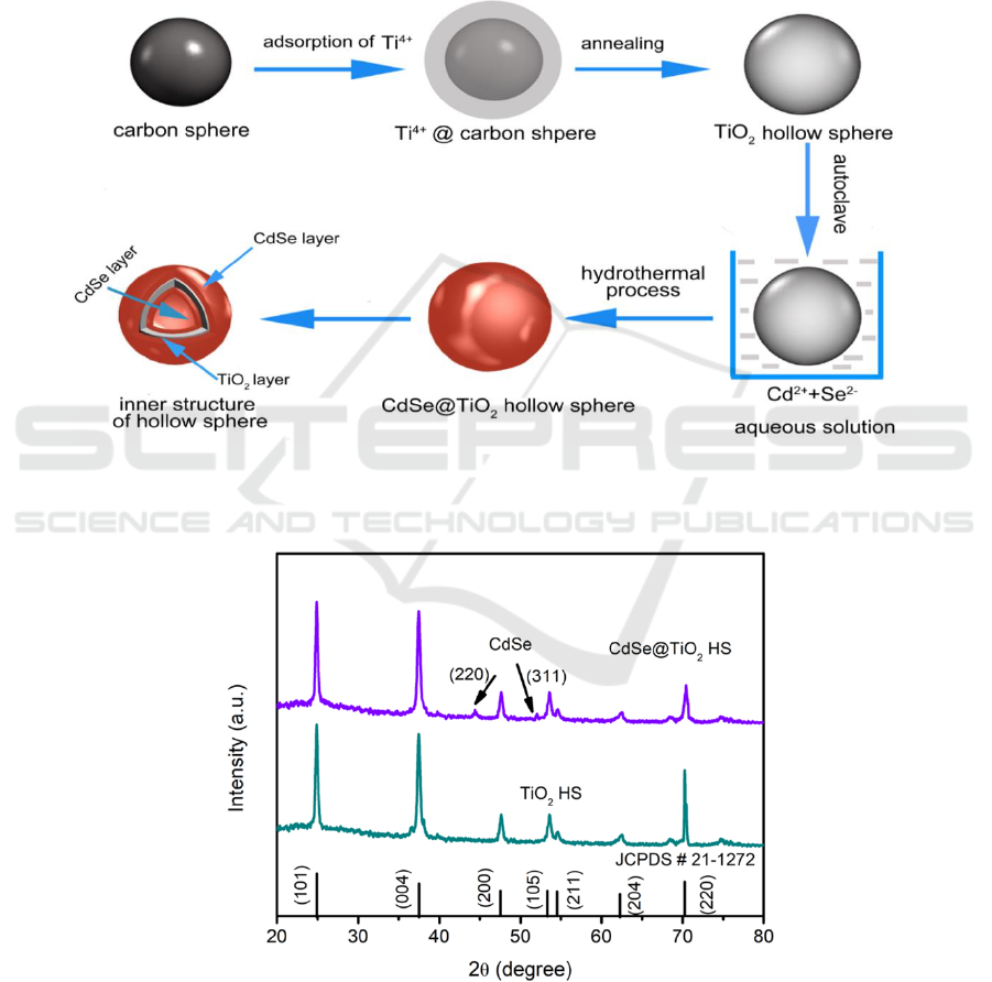
The formation mechanism of CdSe@TiO
2
HS is illustrated in Figure 2 according to SEM and
TEM analysis results. As templates, carbonaceous spheres obtain by hydrothermal reaction of
sucrose play an important role in adsorption of Ti
4+
due to rich carboxyl and hydroxyl function group
on surface of carbonaceous spheres which are affinity to Ti
4+
. After adsorption of Ti
4+
, Ti
4+
@carbon
spheres are annealed in muffle furnace. The carbonaceous spheres are turned in CO
2
, leading to the
formation of TiO
2
HS. The disappearing of carbonaceous spheres is a gradually process due to the
slow temperature increase rate. Hence, the final products of TiO
2
HS show a shrinkage in comparison
with original carbonaceous spheres.
CdSe@TiO2 Hollow Spheres Photoanode for Quantum Dots Sensitized Solar Cells
515
CdSe QDs can be anchored onto TiO
2
HS by hydrothermal process using TGA as linker
molecular. The carboxylate group of TGA has a strong affinity to the TiO
2
, while the thiol group of
TGA can bind strongly to the CdSe QDs through the surface of Cd
2+
. By dipping TiO
2
HS
photoanode in precursor solution, the Cd
2+
and Se
2-
precursors can diffuse into the inside of the TiO
2
HS and bind chemically to the surface of hollow spheres, finally leading to the formation of
CdSe@TiO
2
HS. The CdSe QDs can be decorated on the outer and inner surface of the TiO
2
HS shell
because of the CdSe precursor solution is in ion scale which is beneficial to penetrate into hollow
sphere from all directions.
Figure 2. The illustration of carbonaceous spheres template method to construction of TiO
2
HS and
hydrothermal process to preparation of CdSe@TiO
2
HS.
Figure 3. The XRD pattern of TiO
2
HS and CdSe@TiO
2
HS.
Figure 3 displays the XRD pattern of the TiO
2
HS and CdSe@TiO
2
HS. For the XRD patter of TiO
2
HS, several diffraction peaks can be discerned by careful comparison with standard diffraction
pattern file of anatase TiO
2
(JCPDS # 21-1272), which can be respectively ascribed to the
IWMCE 2018 - International Workshop on Materials, Chemistry and Engineering
516
corresponding planes of (101), (004), (200), (105), (211), (204), (220), indicating the crystal structure
of TiO
2
HS belongs to anatase TiO
2
. After the decoration of CdSe QDs on TiO
2
HS by hydrothermal
process, two other diffraction peaks can be observed around 44.2° and 52.4° for XRD pattern
CdSe@TiO
2
HS. These two diffraction peaks can be ascribed to the (220) and (311) planes of cubic
CdSe (JCPDS #19-0191), demonstrating the successful decoration of CdSe QDs on TiO
2
hollow
spheres.
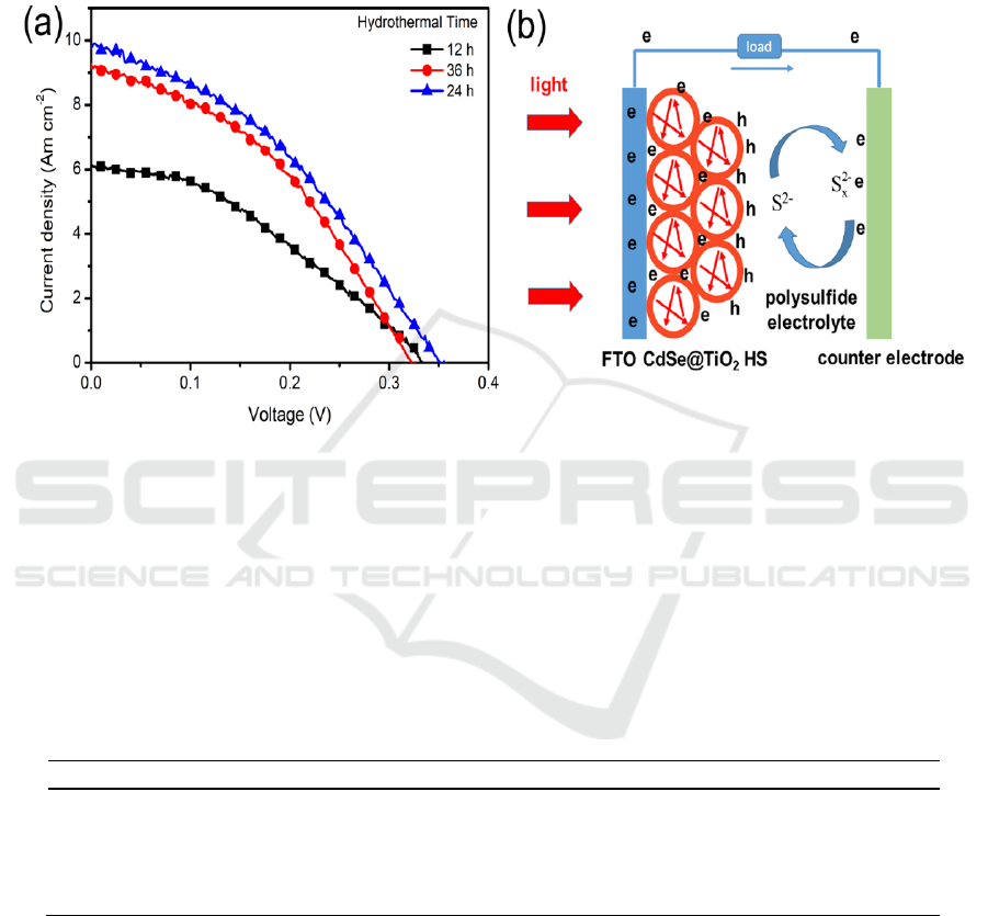
Figure 4. (a) I-V behaviours of CdSe@TiO
2
HS solar cells prepared by different hydrothermal
reaction time; (b) working principle of the CdSe@TiO
2
HS solar cells.
Based on CdSe@TiO
2
HS photoanodes, solar cells are assembled, and the relationship between
photovoltaic performance and hydrothermal reaction time of preparation CdSe@TiO
2
HS were
investigated. Figure 4 (a) shows the I-V curves of solar cells assembled with CdSe@TiO
2
HS
photoanode prepared by 12 h, 24 h, and 36 h of hydrothermal reaction time. Their photovoltaic
parameters including open voltage (V
oc
), short-circuit current density (Am cm
-2
), fill factor (FF), and
power conversion efficiency (PCE) are summarized in table 1.
Table 1. Parameters of CdSe@TiO
2
HS solar cells by different hydrothermal time
time
V
oc
(V)
J
sc
(Am cm
-2
)
FF
PCE (%)
12
0.33
6.11
0.36
0.74
24
0.35
9.78
0.43
1.49
36
0.32
9.26
0.45
1.36
As shown in Figure 4 (a), the best photovoltaic performance of CdSe@TiO
2
HS solar cells is
achieved by 24 h of hydrothermal reaction, which shows a V
oc
of 0.35 V, J
sc
of 9.78 Am cm
-2
, and FF
of 0.43, yielding a PCE of 1.49%. Less or more hydrothermal reaction time (12 h or 36 h) for
CdSe@TiO
2
HS photoanode produced a lower PCE than 24 h. Appropriate increase of hydrothermal
reaction time for CdSe@TiO
2
HS may lead to more CdSe QDs deposition on TiO
2
hollow spheres,
which can absorb more photons to generate excited electrons, resulting in the enhancement of PCE.
However, overdose of CdSe QDs on TiO
2
HS may provide more recombination sites hindering the
CdSe@TiO2 Hollow Spheres Photoanode for Quantum Dots Sensitized Solar Cells
517

efficient electrons transport, and leading to a decrease of PCE as indicated by CdSe@TiO
2
HS solar
cells prepared by 36 h of hydrothermal process.
Figure 4(b) illustrated the working principle of CdSe@TiO
2
HS solar cells. The great potential to
use TiO
2
HS as supporting architecture in QDSSCs is that the hollow sphere structure not only
provides enough space for adsorption of QDs, but also generates an effect of full utilization of light
caused by multiple times reflection of light inside of hollow spheres as shown Figure 4 (b), leading to
the enhancement of light harvesting efficiency. When light is fully utilized to excite QDs generate
more electrons, the photovoltaic performance of QDSSCs can be improved. Therefore, our
CdSe@TiO
2
HS solar cell produced an acceptable PCE of 1.49%, showing great potential application
of TiO
2
hollow spheres in design of QDSSCs.
4. Conclusions
The TiO
2
hollow spheres were synthesized using carbonaceous spheres template method.
Furthermore, CdSe@TiO
2
hollow spheres photoanode were constructed by a simple hydrothermal
process using TGA as linker molecular. The TEM, SEM, and XRD analysis results proved our
strategy is feasible to obtain CdSe@TiO
2
hollow spheres photoanode for QDSSCs. The photovoltaic
performance analysis results showed that the hydrothermal reaction time can influence the I-V
behaviours of CdSe@TiO
2
hollow spheres solar cells. The QDSSCs with a better PCE of 1.49% can
be obtained by 24 h of hydrothermal reaction time. The proposed working principle of the solar cell
implies a potential application of TiO
2
hollow spheres for design of high power conversion efficiency
QDSSCs.
Acknowledgments
This work has been financially supported by the University Research Project of Gansu Province
[grant number 2017A-089], the Surface Project of Key Laboratory of Hexi Corridor Resources
Utilization of Gansu Province [grant number XZ1604], and the Hexi University Principle Fund of
Scientific Innovation and Application [grant number XZ2017010].
References
[1] Ren X, Yu L, Li Z, Song H and Wang Q 2018 Superlattices Microstruct. 113 696-705
[2] Lu Y B, Li L, Su S C, Chen Y J, Song Y L and Jiao S J 2017 RSC Adv. 7 9795-9802
[3] Li Z, Yu L, Liu Y and Sun S 2014 Electrochim. Acta 129 379-388
[4] Choi Y, Seol M, Kim W and Yong K 2014 J Phys. Chem. C. 118 5664-5670
[5] Cai Y, Wang H E, Zhao X, Huang F, Wang C, Deng Z, Li Y, Cao G and Su B L 2017 ACS
Appl Mater Interfaces 9 10652-10663
[6] Zhang Q, Chou T P, Russo B, Jenekhe S A and Cao G 2008 Angew Chem. Int. Ed. Engl. 47
2402-2406
[7] Lai X, Li J, Korgel B A, Dong Z, Li Z, Su F, Du J and Wang D 2011 Angew. Chem. Int. Ed.
Engl. 50 2738-2741
[8] Du J, Qi J, Wang D and Tang Z 2012 Energy & Environmental Science 5 6914
[9] Ren H, Yu R, Wang J, Jin Q, Yang M, Mao D, Kisailus D, Zhao H and Wang D 2014 Nano
Lett 14 6679-6684
[10] Wang Y, Shu Y, Xu J and Pang H 2017 Cryst Eng Comm 19 684-689
[11] Wang Y, Liu T, Huang Q, Wu C, Shan D and Mater J 2016 Res. 31 2317-2328
IWMCE 2018 - International Workshop on Materials, Chemistry and Engineering
518
