
Experimental Investigation of the Water Erosion Resistance
of Turbine Blade Materials at Different Impact Angle
Z Y Zhang
1
, Y H Xie
1,*
and D Zhang
2
1
School of Energy and Power Engineering, Xi’an Jiaotong University, Xi’an,
Shaanxi Province, 710049, P. R. China
2
Key Laboratory of Thermal Fluid Science and Engineering of Ministry of Education,
School of Energy and Power Engineering, Xi’an Jiaotong University, Xi’an, Shaanxi
Province, 710049, P. R. China
Corresponding author and e-mail: Y H Xie, yhxie@mail.xjtu.edu.cn
Abstract. In order to simulate the water e rosion process of blades in final turbine stage under
the actual operating conditions, the water erosion experiment system has been designed and
built in the present research. High-speed water jet was used to impact three kinds of structural
steel material under three impact angle (30°, 60°, and 90°) to obtain the cumulative erosion-
time curves of specimen. The incubation period and maximu m erosion rate are chosen as the
criterion to evaluate the erosion resistance of the testing materials. Based on the mechanical
properties of testing materials, it is figured out that water erosion resistance of materials is
influenced by different mechanical properties (hardness, tensile Strength, elasticity and shear
modulus) at different stages. According to the characteristic size changes in width and depth
of erosion craters, it is verified that the shear effect of lateral jet is greater than the impact
effect of normal jet.
1. Introduction
In the steam turbine of modern large-scale thermal and nuclear power plants, there is always two-
phase condensation flow of wet steam. The steam humidity reduces the working efficiency.
Meanwhile, a large number of water droplets entrained in the steam may cause serious water erosion
damage to blades, which reduces the fatigue life of blades and threatens the safe operation of the
equipment seriously. Therefore, studying the factors influencing the water erosion resistance and its
changing rules are of great engineering value for development of new blades.
In recent years, many researchers have devoted themselves to the theoretical study of the
mechanism of water erosion. However, due to the complexity of water erosion process, a set of
complete and mature theoretical system has not yet been formed. So many researchers have adopted
experimental methods to simulate the water erosion process. Adopting the experimental method and
scanning electron micrograph, Mann [1] respectively studied the erosion progress of the titanium
alloy, laser hardened Hadfield steel, plasma nitrided and pack borided 12Cr steel under high-speed jet
impingement. Briscoe [2] designed and built a set of water jet device. The jet erosion process of a
Zhang, Z., Xie, Y. and Zhang, D.
Experimental Investigation of the Water Erosion Resistance of Turbine Blade Materials at Different Impact Angle.
In Proceedings of the International Workshop on Materials, Chemistry and Engineering (IWMCE 2018), pages 221-228
ISBN: 978-989-758-346-9
Copyright © 2018 by SCITEPRESS – Science and Technology Publications, Lda. All rights reserved
221

polymer-particle coating system was investigated. Based on the experimental data, two modified
wear models were proposed. Hancox [3] studied the influence of surface roughness on erosion effect.
It was found that when the surface roughness changed from 12 to 1μm, the erosion effect decreased
by 4 times, but when the surface roughness was greater than 12μm, the surface roughness had no
effect on the erosion performance. Seleznev [4] simulated the erosion process of constructional steels
and alloys impacted by droplet and drew the material mass loss curves. Mahdipoor [5] also adopted
experimental method to investigate the water erosion resistance of WC-Co coatings deposited by
high velocity oxygen fuel process. The erosion mechanism of brass, stainless steel and alloy was
studied through the rotating jet impact test platform by Thomas [6]. Based on the analysis of applied
energy intensity, three kinds of structural materials were tested under several erosion condition by
Kirols [7]. In his study, a severity coefficient (ζ) was proposed to compare the results done at various
erosion conditions or on different test rigs. The author mentioned that different droplet diameter and
imping velocity may produce the same erosion effect. Heymann [8] proposed a relationship of the
maximum erosion rate, water droplet diameter, crater size, and other parameters. Oke [9] studied the
water erosion characteristics of different ceramic materials, cermet coatings and martensitic stainless
steels. Thiruvengadam [10] used experimental methods to determine the threshold velocity and
threshold water pressure of jet damage for the specific material. According to the experimental
results, the function relation between water erosion rate and erosion time was proposed. The
influence of target surface shape coefficient on water erosion process was pointed out. On the basis
of experimental data, Lee [11] proposed a new model for water erosion analysis. The specific fitting
formula of water flow rate, erosion velocity, water droplet diameter, target material hardness and
average erosion rate were put forward.
To sum up, many scholars have done a lot of research in the water erosion investigation. However,
due to the limitation of the equipment, most of experimental conditions did not reach the actual
operation parameters of turbine blade. With the continuous updating of materials, the early research
results have not been of great reference value for the design and manufacture new blade. In order to
solve this problem, an experimental platform for water erosion is introduced in this paper. The water
erosion characteristics of three kinds of steam turbine blade materials under three impact angles are
given and the difference of their water erosion resistance are compared. Based on the mechanical
property parameters and local micrographs, the characteristic size change law of erosion cracks is
obtained. The results could provide theoretical support for the design and manufacture of new steam
turbine blades.
2. Experimental system and material information
2.1. Introduction of experimental system
In order to study the water erosion characteristics of low pressure blades of turbine and obtain the
water erosion resistance of commonly used materials, a rotating test platform for water erosion
characteristics of low pressure blades of turbine was designed and constructed in the present study.
The basic principle is shown in figure 1 and the physical picture is shown in figure 2.
IWMCE 2018 - International Workshop on Materials, Chemistry and Engineering
222
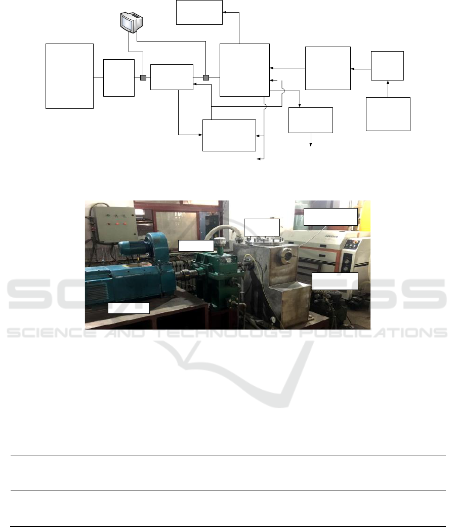
Controller
Cabinet
DC
Motor
Gearbox
Testing
Section
High-
Pressure
Pump
Draining
Pump
Lubrication
Station
Distillate
Tank
Filter
Vacuum
Pump
Computer
Water
Jet
Vibration Signal
Speed Signal
Figure 1. Schematic diagram of water erosion experimental system.
High-Pressure
Pump
Testing
Section
Lubrication
Station
Gearbox
DC Motor
Figure 2.Physical picture of water erosion experiment system.
2.2. Information of testing materials
In this experiment, three kinds of high strength structural steel materials were used as test objects,
and the specific parameters of materials are shown in table 1. Each material was used to make
experimental specimen with three angles in order to compare the effect of material property and
impact angle on the water erosion characteristics.
Table 1.Mechanical properties of the testing materials.
Serial
number
Material
Hardness
(HB)
Tensile Strength
(MPa)
Elasticity
Modulus
(×10
5
MPa)
Shear
Modulus
(×10
4
MPa)
1#
Martensitic stainless steel
398
1295
1.973
7.59
2#
Precipitation hardening steel
425
1517
—
—
3#
Heat-resisting stainless steel
358
1105
2.066
7.915
3. Experimental method
3.1. Experimental condition
The experimental system can simultaneously carry out high-speed jet erosion test on the testing
material specimen. The experimental conditions used in this paper are shown in the table 2.
Experimental Investigation of the Water Erosion Resistance of Turbine Blade Materials at Different Impact Angle
223
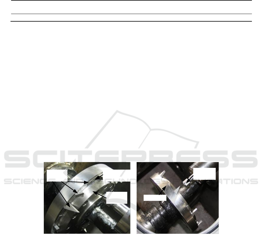
Table 2.Experimental conditions in the present study.
Item
Rotate Speed
(r/min)
Vacuum Pressure
(kPa)
Nozzle Pressure
(MPa)
Nozzle diameter
(μm)
Impact Velocity
(m/s)
Value
1500
14
234.43
150
638.4
In this paper, 3D ultra-depth microscopy was used to observe the surface micrograph of specimen
and obtain the characteristic size of erosion craters. In order plot the cumulative erosion-time curves,
the precision balance was used to obtain the mass loss of the specimen. At the initial stage of the
experiment, specimen were weighed at a shorter time interval to determine the fine mass changes. In
the later stage, when the erosion rate is stable, a longer interval was used to save the time and
improve the experimental efficiency.
3.2. Layout of the testing specimen
The layout of the specimen is shown in figure.3. The testing specimen and the fan-shaped blocks
were arranged in the wheel disc alternately and tightly. Then the pressing plate was covered to fix the
relative position of the testing specimen during the experiment. The signals of rotor speed and
vibration were monitored by sensors to ensure the stable and safe operation of the system.
As shown in figure 3, the testing specimen were manufactured into different shapes to ensure a
certain impact angle between water jet and target surface. In the present study, three kinds of
specimen shapes correspond to the three impact angles (30°, 60°, and 90°). In order to facilitate
statement, these three types of specimen are called 30° specimen, 60° specimen and 90° specimen
hereinafter respectively.
Testing
specimen
Pressing
plate
Fan-shaped
Block
Water Jet
Nozzle
Wheel disc
Figure 3.The testing sample layout diagram.
4. Results and discussion
4.1. Cumulative Erosion-Time Curve
According to the ASTM standard G73-10[12], an erosion curve is usually divided into five sections:
(a) incubation stage, (b) acceleration stage, (c) maximum erosion rate stage, (d) deceleration stage,
and (e) terminal steady state stage. The cumulative curves of the present testing material specimen
are shown from figure 4. As can be seen from the figures, for the martensitic stainless steel, at the
initial stage of the experiment, the water erosion rate of 90° and 60° specimen were greater than that
of 30° specimen. The mass loss rate of the 90° specimen was obviously accelerated at 120 minutes of
erosion and decreased slightly at 240 minutes. For the precipitation hardening steel material, there
was obvious water erosion incubation period at the initial stage for 30° and 60° specimen because of
little mass loss. For the heat-resisting stainless steel, at the beginning of the experiment, the erosion
IWMCE 2018 - International Workshop on Materials, Chemistry and Engineering
224
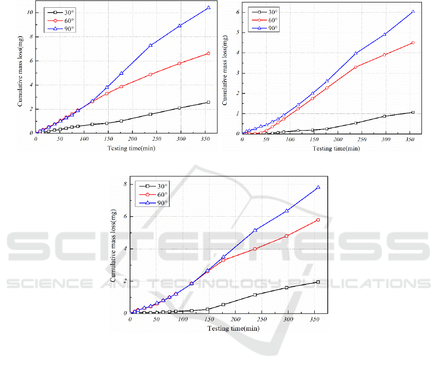
rate of 60° and 90° specimen remained alike and the 30°specimen had almost no mass loss. However,
90° specimen had a longer time of water erosion acceleration, resulting in more accumulated mass
loss than 60° specimen. And the mass loss of 30°specimen was the least.
(a) Martensitic stainless steel (b) Precipitation hardening steel
(c) Heat-resisting stainless steel
Figure 4. Cumulative erosion-time curve of testing material.
4.2. Water erosion resistance performance
According to the ASTM standard G73-10[12], based on the cumulative erosion-time curves, the
tangent at the point of maximum erosion rate was plotted and the corresponding equations were
obtained. The intercept in the x axis and slope of each tangent represents the corresponding
equivalent incubation period (Ip) and the maximum erosion rate (Q
e
), which are given in figure 5. For
the present testing material, the incubation period of 30° specimen is the longest, 90° specimen
shorter and 60° specimen is the shortest. Specimen of precipitation hardening steel shows the longest
incubation period at different impact angles, followed by heat-resisting stainless steel and martensitic
stainless steel specimen is the shortest.
Experimental Investigation of the Water Erosion Resistance of Turbine Blade Materials at Different Impact Angle
225
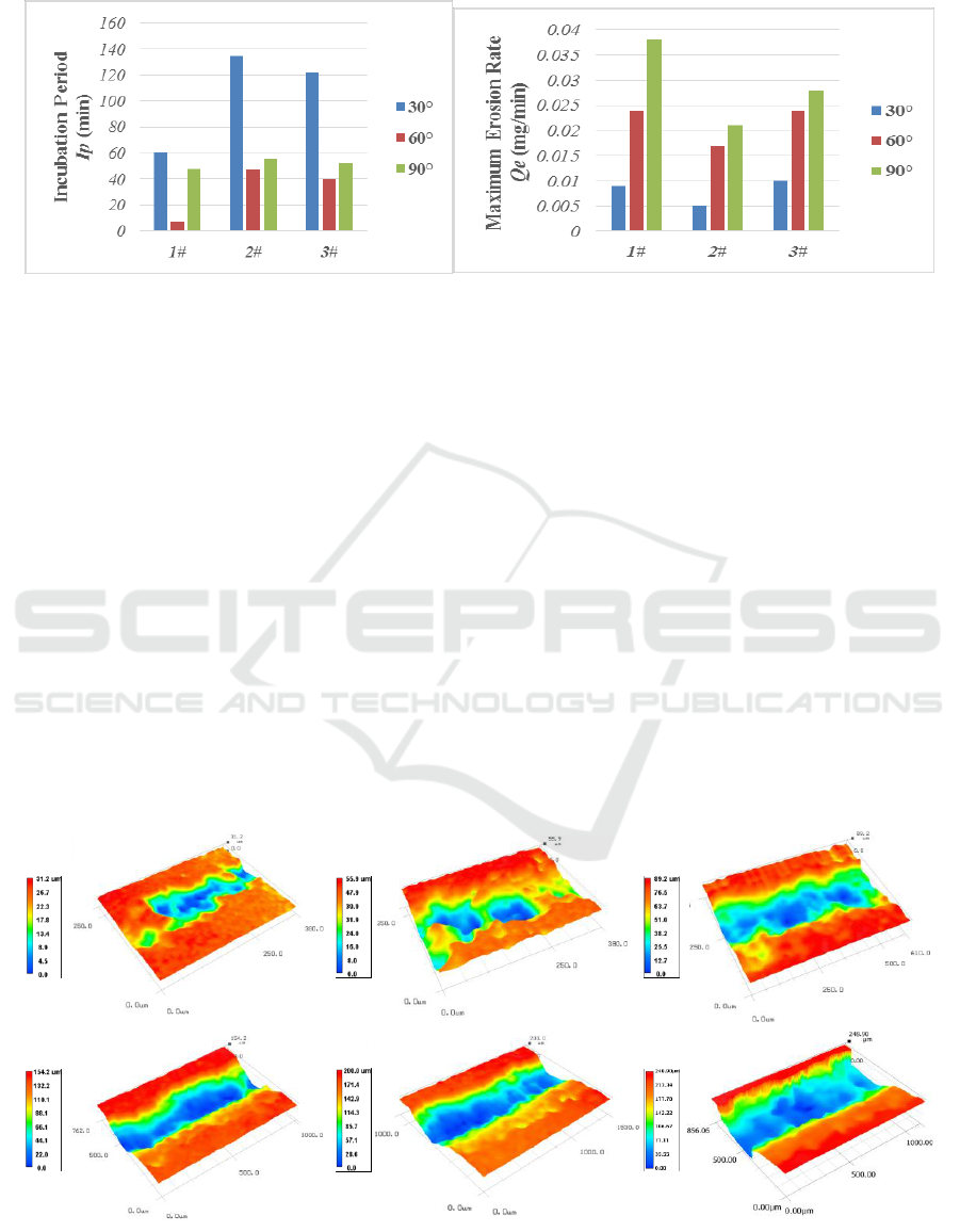
(a)Incubation period(Ip)
(b)Maximum erosion rate(Q
e
)
Figure 5. Column chart of material’s water erosion coefficient.
As can be seen from figure 5, as the angle of water erosion increases, the maximum mass erosion
rate increases. For precipitation hardening steel, the maximum mass erosion rate is obviously smaller
than that of other two kinds of materials, which shows its superior erosion resistance to other two
kinds of materials. It can be reduced from the comparison between martensitic stainless steel and
heat-resisting stainless steel, that elastic modulus and shear modulus are the main factors affecting
the water erosion incubation period. The incubation time of martensitic stainless steel material is
shorter due to its higher elastic modulus and shear modulus. However, once the defect occurs, the
influence of elastic modulus and shear modulus is weakened, and the effect of hardness and tensile
strength on the material is enhanced. Therefore, the heat-resisting stainless steel shows a smaller
maximum rate of water erosion.
4.3. Water-erosion morphology
The microscopic 3D morphology of martensitic stainless steel material at 90° impact angle are given
in figure 6. It can be seen that only a series of discrete craters were produced in the initial erosion
stage. Then the number of craters increased and eventually developed into an erosion groove. Under
the scouring effect of the lateral jet, the edge of the water erosion groove was smoothed gradually.
15min 39min 87min
117min 237min 357min
Figure 6.3D Micrograph of water erosion area of martensitic stainless steel material 90° specimen.
IWMCE 2018 - International Workshop on Materials, Chemistry and Engineering
226

The erosion groove size of 60° specimen for precipitation hardening steel at different times are
shown in table 3. It can be seen that the expansion rate of width was obviously higher than that of
depth at the beginning of the experiment, which indicates that the main reason for the expansion of
the grooves is the shear effect of the lateral jet at this stage. After that, due to the formation of water
film on the side wall, the expansion of the groove width is slowed down.
Table 3.Characteristic sizes of erosion grooves for 60° specimen of precipitation hardening steel.
Time(min)
15
39
87
117
237
357
Depth(μm)
13.73
22.3
40.3
43
77.93
121.55
Width(μm)
33.27
133.8
335.43
393.8
495.17
498.67
5. Conclusions
The experimental investigation on water erosion characteristics of three kinds of structural steel
materials at three impact angles was carried out in the present study. A detailed analysis of the water
erosion characteristics of each material of each stage and the curves of mass loss were obtained.
The water erosion resistance of three kinds of materials were compared based on the incubation
time (Ip) and maximum erosion rate (Q
e
). According to the mechanical parameters of materials, it is
found that the incubation time is mainly influenced by elastic modulus and shear modulus. Once the
defect occurs, the effect of hardness and tensile strength on the material is gradually enhanced.
The influence of impact angle on the water erosion resistance of materials was studied. On the one
hand, the greater impact angle causes the greater erosion rate. On the other hand, the 60° specimen
shows the shortest erosion incubation period for the testing three materials, which indicates that there
is the most dangerous water impact angle under the present experiment condition.
For the erosion grooves, the expansion rate of width was 2 times greater than that of the depth in
the early stage of the experiment, which indicates that the lateral jet produced by high-speed jet
impingement is the main factor of erosion groove expansion. Once the defect on the surface formed,
the shear effect of the lateral jet accelerated the expansion of the groove size, which resulted in the
acceleration of the mass loss. In the late erosion stage, due to the formation of the water film on the
side wall, the expansion speed of the groove size was slowed down to different degrees.
References
[1] Mann B S, Arya V 2002 An experimental study to corelate water jet impingement erosion
resistance and properties of metallic materials and coatings [J]. Wear 253(5) 650-661
[2] Briscoe B J, Pickles M J, Julian K S, et al. 1997 Erosion of polymer-particle composite
coatings by liquid water jets [J]. Wear 203: 88-97
[3] Hancox N L and Brunton J H 1966 The erosion of solids by the repeated impact of liquid
drops [J]. Philosophical Transactions of the Royal Society of London, Series A 260 (1110)
121-139
[4] Seleznev L I, Ryzhenkov V A and Mednikov A F 2010 Phenomenology of erosion wear of
constructional steels and alloys by liquid particles [J]. Thermal engineering , 57(9) 741-745
[5] Mahdipoor M S, Tarasi F, Moreau C, et al. 2015 HVOF sprayed coatings of nano-
agglomerated tungsten-carbide/cobalt powders for water droplet erosion application [J].
Wear 330 38-347
[6] Thomas G P and Brunton J H 1970 Drog impingement erosion of metals [J]. Proceedings of
the Royal Society of London, Series A 14 (1519) 49-565
[7] Kirols H S, Mahdipoor M S, Kevorkov D, et al. 2016 Energy based approach for
understanding water droplet erosion [J]. Materials & Design 04 6-86
Experimental Investigation of the Water Erosion Resistance of Turbine Blade Materials at Different Impact Angle
227

[8] Heymann F J 1967 A survey of clues to the relationship betweenerosion rate and impact
parameters Proceedings of the Second Meersburg Conference on Rain Erosion and Allied
Phenomena Held on the Bondensee, Fedreal German Republic, 16th–18th August 683–
760
[9] Oka Y I and Miyata H 2009 Erosion behaviour of ceramic bulk and coating materials caused
by water droplet impingement [J]. Wear 267(11) 1804-1810
[10] Thiruvengadam S L R, 1969 Experimental and analytical investigations onmultiple liquid
impact erosion, Hydronautics Inc., National Aeronautics and Space Administration, NASA
CR-1288
[11] Lee B E, Riu K J, Shin S H, et al. 2003 Development of a water droplet erosion model for
large steam turbine blades[J]. Journal of Mechanical Science and Technology 17(1) 114-
121
[12] ASTM Standard G73 2010 Standard Test Method for Liquid Impingement Erosion Using
Rotating Apparatus, ASTM International West Conshohocken, PA.
http://dx.doi.org/10.1520/G0073-10, www.astm.org
IWMCE 2018 - International Workshop on Materials, Chemistry and Engineering
228
