
Modeling Method of the L-Type Co-Use of Weld and Bolts Joint
Interface
Yi Xin
1,a
, Jianfu Zhang
2,b
Jingping Liao
2,c
and Yantao Wang
1,d
1
YanTai University, Shandong 264000, China,
2
Department of Mechanical Engineering, Tsinghua University,
Beijing 100084, China,
a
543804675@qq.com,
b
zhjf@tsinghua.edu.cn,
c
wuzhijun@tsinghua.edu.cn
d
tomsmarter@163.com
Keywords: Weld and bolts joint interface structure, virtual gradient material, dynamic characteristic, modeling mothed.
Abstract In order to analyze the dynamic characteristic of a co-use of weld and bolts joint structure, this paper, based
on the virtual gradient material model and two welded joint interface modeling methods, proposed a
modeling method of the L - type co-use of weld and bolts joint interface. The natural frequency and
vibration mode of the co-use of weld and bolts joint structure were studied according to simulation and
experimental researches. The natural frequency of two kinds of joint surface modeling methods are
respectively obtained. Modal test analysis was then carried out to verify what kind of modeling method is
more effective and feasible. The results shows that the 45°weld rigid connection model is consistent with
the first six-order vibration mode shapes of the experimental mode. The relative errors of corresponding
natural frequencies between the model and the experiment are less than 5%, which have higher modeling
accuracy.
1 INTRODUCTION
In order to meet the requirements of functions,
performance and transportation, machineries and
equipments are composed of parts according to
some certain requirements. During the mechanical
dynamic design, reasonable dynamic parameters of
the joint surface and the dynamic mechanism of the
bounding surface itself play an important role in
establishing an accurate dynamic model (
S. T. Wang
et al., 2008
). Therefore, research on the dynamic
characteristics of the interface is of great
significance.
At present, there has been great progress in the
study of the stress performance of co-use of weld
and bolts joint structure at home and abroad. Some
scholars have conducted experimental and finite
element analysis. Sun Lei et al. (2007) through the
finite element analysis, proved that co-use of side
weld and bolts joint structure worked well in
together through the finite element analysis. Wang
Yongzhe et al. (2011) proved that the high strength
bolt could reduce the stress of the weld joint,
restrained the crack propagation, improved the
stiffness of the structure and prolonged the fatigue
life of the structure effectively. The determination of
the connection area is based on experience in most
studies, without considering the influence of the
surface pressure and distribution of the bolt on the
joint surface, therefore, it is not suitable for
simulating preload in linear modal analysis (Jeong
Kim, 2007).
In this paper, finite element analysis and
performance experiments,for the L-type co-use of
weld and bolts joint structure were carried out. The
advantages and disadvantages of two different
modeling forms are discussed.
2 MODELING METHOD
2.1 Bolt Joint Interface Modeling
In the virtual gradient material method, the bolted
joint is equivalent to a kind of local virtual gradient
material. The contact pressure distribution of the
bolt joint surface is obtained by finite element
method. Finite element analysis software ANSYS is
used to analyze the pre-tightening force of the bolted
joints, as shown in Fig.1. Two-dimensional
axisymmetric finite element model of M6 bolt
400
Xin, Y., Zhang, J., Liao, J. and Wang, Y.
Modeling Method of the L-Type Co-Use of Weld and Bolts Joint Interface.
In 3rd International Conference on Electromechanical Control Technology and Transportation (ICECTT 2018), pages 400-404
ISBN: 978-989-758-312-4
Copyright © 2018 by SCITEPRESS – Science and Technology Publications, Lda. All r ights reserved
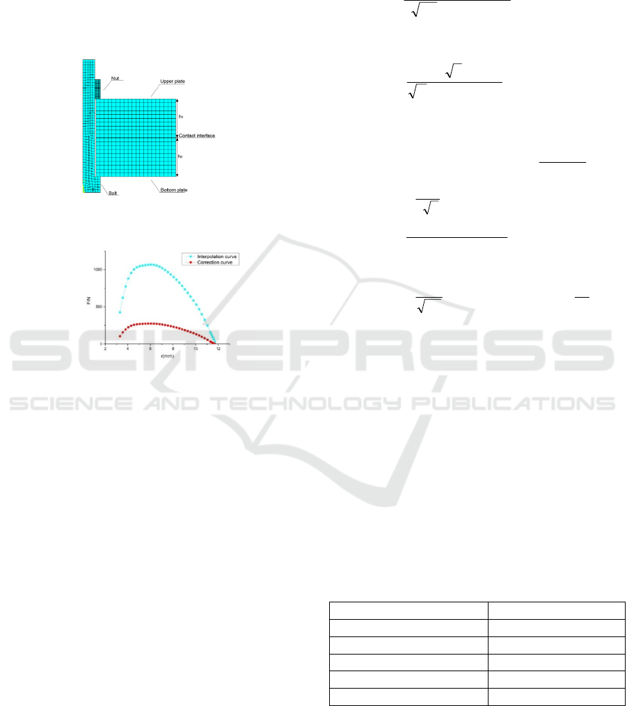
connection was established. The material was Q345,
the thickness was h
1
=h
2
=10mm, and the preload was
6666.7N. Filtering the contact line and extracting the
initial nodal contact forces, interpolating them could
improve the characterization accuracy. The curve
was scaled down so that total force was equal to the
bolt preload after correction. The interpolation and
correction of the nodal contact forces curve was
shown in Fig.2.
Figure 1: finite element model of the single bolted joint.
Figure 2: Contact pressure distribution curve.
After obtaining the pressure distribution curve,
fourth degree polynomial was used to fit the
pressure distribution curve of the bolt joint surface.
Under 95% confidence bounds, linear least squares
regression technique was used to the contact
pressure data to estimate the relevant parameters. In
order to make the pressure at the maximum contact
radius of the fitting curve equal to zero and the total
pressure equal to the pre-tightening force of the bolt,
subtracting a constant was subtracted from the
fitting curve and the fitting curve was scaled down
(L. Wang et al., 2013). The normal contact pressure
can then be expressed by
57.1732.120
3.24022.2061.0)(
234
−+
−+−=
r
rrrrP
(1)
where r is the radius from the center of the bolt hole.
The pre-tightening force
(i=1,2,3)can obtain with
diffident r .
The properties of the virtual gradient material are
Z-direction’s elastic modulus E
Z
, equivalent elastic
modulus
, XY plane’s shear modulus G
xy
,
equivalent shear modulus
,poisson's ratio and
density (J.P. Liao et al., 2016).The key parameters
for them are calculated by
])(
)[(
)5.05.0(2
)(
5.05.0
5.05.0
5.05.01*
D
C
D
L
D
L
D
ni
a
a
D
aDE
K
−
−
−
−
×
−
=
π
ψ
(2)
])()[()(
)2)(1(
22
5.05.05.05.05.0
5.01
D
c
D
L
D
L
D
i
aaa
D
D
G
K
−−
−
−
×
−−
=
ψ
μπ
τ
(3)
⎪
⎪
⎪
⎪
⎪
⎪
⎪
⎩
⎪
⎪
⎪
⎪
⎪
⎪
⎪
⎨
⎧
=
+
≠
−
−
+
−
=
−−
−−
−
−
5.1
)()0007.2(
2
)0007.2()(5.1
5.1
5.1
)()(
)(
23
2
5.01
)(
)(25.0
75.025.05.0
*
25.075.0
5.015.1
5.05.011
*
5.01
5.05.01
D
a
a
InaG
E
aaK
D
D
aa
aDG
E
D
a
aDK
F
c
L
L
c
D
Ly
D
c
D
L
D
L
DD
D
c
D
L
D
y
i
π
σ
ψ
ψσ
(4)
Where D is fractal dimension, ψ is parameters
determined by the fractal dimension D, G is fractal
feature length scale, a
L
is the maximum contact area
of the micro convex body, a
c
is the critical contact
area of the micro convex body, K=H/σ
y
, where H is
the hardness of the softer material, σ
y
is the yield
strength of the softer material.
The above mentioned virtual gradient material
method is used to simulate a bolt-connected plate on
the L-type co-use of weld and bolts joint structure.
The size of the two plates are (150 × 150 × 10) mm.
The two plates are connected by 4×M6 bolts. The
parameters of the plates are listed in Table 1.
Table 1: Q345 material parameters.
parameter Value
Elastic Modulus(GPa)
210
Poisson's ratio 0.3
density(
⁄
)
7800
hardness(MPa) 500
Yield Strength(MPa)
345
For the model of virtual gradient material, the
more the layers are used the closer the solution to
the theoretical value. However, considering the
computational efficiency, the material is evenly
divided into three layers as shown in Fig.3. The
Modeling Method of the L-Type Co-Use of Weld and Bolts Joint Interface
401
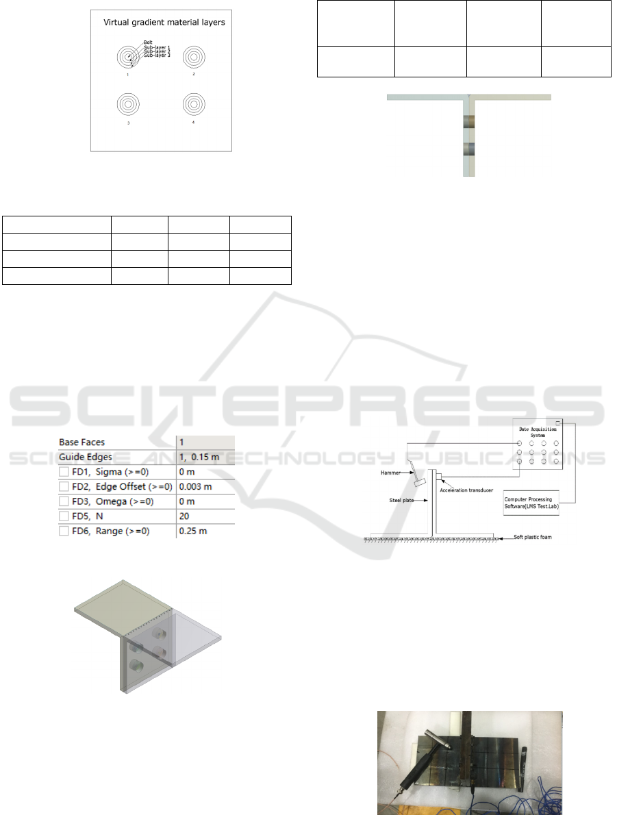
parameters for each sub-layer of the virtual gradient
material were shown in Table 2.
Figure 3: Virtual gradient material finite element mode.
Table 2: Property parameters of each sub-layer.
Sublayer 1 2 3
Contact force F(N) 2659 2604 1404
(GPa) 11.4 5.1 1.7
(GPa) 9.4 4.3 1.4
2.2 Weld joint interface modeling
There are two methods to build the finite element
model of welded joint interface. One is to create
some rigid connection points by creating point in
ANSYS workbench instead of the solder joints for
simulation. The parameters are set up and the model
is established as shown in Fig.4 and Fig.5.
Figure 4: Create the solder joints parameter setting.
Figure 5: Solder joint finite element model.
Another way is to set the weld material, taking
into account the groove size. The electrode using
E5015 electrode whose material parameters were
shown in Table 3. 45 ° weld angle was adopted to
establish the model, as shown in Fig.6.
Table 3: E5015 electrode parameters
Specimen
material
Elastic
Modulus
/GPa
Poisson's
ratio
Yield
Strength
/MPa
E5015
electrode
1500 0.3 400
Figure 6: 45 ° weld rigid connection model.
3 EXPERIMENTAL
VERIFICATION
In order to verify the effectiveness of the proposed
modeling method in this paper, a test piece which is
consistent with the simulation model, modal
experiments were carried out. The modal test system
is shown in Fig.7. The test piece consists of two
L-shaped steel plates which joined together by
bolting and welding. The dimensions of the joint are
150 mm × 150 mm.
Figure 7: Test modal of the L-shaped structure.
The specimen was placed on the soft plastic
foam to simulate a free boundary. A piezoelectric
accelerometer (PCB 356A15) was used to record the
vibration response of PCB 086C03 impact hammer.
The LMS SCADAS III multichannel data
acquisition system was used to acquire and process
dynamic testing data. The specimen modalities were
measured by the hammer, as shown in Fig.8.
Figure 8: Experimental test.
ICECTT 2018 - 3rd International Conference on Electromechanical Control Technology and Transportation
402
A 16-node specimen test model was established
on one side of the joint and then knocked them one
by one. Through the LMS Test. Lab mechanical
vibration test system, the natural frequencies under
each pre-tightening torque can be obtained. The
experimental and simulation results were compared
in Table 5. The simulation errors of the two models
are less than 8% which are less than no weld model.
The experimental results show good agreement with
45 ° rigid connection model. The comparison of first
six-order mode shapes for the 45 ° rigid connection
model and experiments is illustrated in Table 5. The
results indicates that the 45 ° rigid connection model
mode shapes show good agreement with the
experimental shapes.
Table 4: Comparisons of the first six-order vibration mode.
Natu
ral
frequ
ency/
Hz
No
Weld
mode
l
Spot
spaci
ng
7.5m
m
Spot
spaci
ng
5mm
Spot
spaci
ng
2mm
Spot
spaci
ng
1.7m
m
45°
Rigid
conta
ct
Expe
rime
ntal
result
s
Error
of no
Weld
mode
l
Error
of
spaci
ng
7.5m
m/%
Error
of
spaci
ng
5m
m(%
)
Error
of
spaci
ng
2m
m(%
)
Error
of
spac
ing
1.7m
m(%
)
Error
of
45°
Rigid
conta
ct(%)
317.9 475.7 477.0 482.5 480.6 467.7 448.5 -41 6.08 6.36 7.6 7.17 4.29
498.7 587.3 587.4 588.9 588.0 582.4 579.9 -16.2 1.27 1.3 1.55 1.4 0.43
669 888.1 887.8 891.1 890.5 881.8 874.1 -30.7 1.61 1.58 1.96 1.89 0.89
808.7 1021 1023 1028 1027 1012 1013 -25.3 0.84 0.99 1.53 1.42 -0.11
1133 1337 1338 1342 1340 1329 1379 -21.6 -3 -2.99 -2.67 -2.79 -3.61
1152 2136 2137 2140 2139 2126 2124 -84.4 0.55 0.58 0.74 0.68 0.06
Table 5: Comparison of 3 kinds of theoretical and experimental mode shapes.
order
1 2 3 4 5 6
Experiment
al mode
shape
45° Rigid
contact
weld mode
shape
4 CONCLUSION
(1) Considering the influence of the bolt distribution
on the joint surface, the model of the bolt joint
interface was established by a virtual gradient
material method. In order to obtain a more accurate
modeling method of the weld joint interface, the
create solder joints method and rigid connection
method was analyzed.
(2) The experimental modal and the simulation
analysis modal were compared. The first six-order
vibration mode shape of the simulation was
corresponding to the experimental results. The
relative error of the first six-order vibration mode
natural frequencies of 45° rigid connection model
were within 5%. It showed that this method was
more effective to simulate the weld join.
ACKNOWLEDGMENTS
We gratefully acknowledge the financial support for
this research from the National Natural Science
Foundation of China (Grant No. 51575301).
Modeling Method of the L-Type Co-Use of Weld and Bolts Joint Interface
403

REFERENCE
S. T. Wang et al., Study on dynamic characteristics of
typical mechanical interface and its application
[D].Kunming university of technology, 2008
Sun L.Experimental research and FEA analysis of
combined joint with bolts and welds, D. Beijing:
Central research Institute of Building and
Construction, 2007 ( in Chinese)
H. L. Tian et al., A new method of virtual material
hypothesis-based dynamic modeling on fixed joint
interface in machine tools[J].International Journal of
Machine Tools & Manufacture,2011,51(3):239-249.
Jeong Kim,Joo-Cheol Yoon,Beom-Soo Kang.Finite
element analysis andmodeling of structure with bolted
joints,Applied Mathematical Modelling[J],2007
(31):895-911
L. Wang et al., Matching design for bolted joints based by
effective contact radius maximization, J. of Xi'an
Jiaotong University, 47 (7) (2013) 62-67.
J.P. Liao et al., Interface contact pressure-based virtual
gradient material model for the dynamic analysis of the
bolted joint in machine tools. Journal of Mechanical
Science and Technology, 2016 30(10):.
ICECTT 2018 - 3rd International Conference on Electromechanical Control Technology and Transportation
404
