
Study of the Establishment of Typical Wind Speed Model Based on
Numerical Simulation
Yuanyuan Zhao
Tianjin Light Industry Vocational Technical College, China, 300192
Keywords: Extremely related gusts, FLUENT Modeling, numerical simulation.
Abstract: The wind power industry in our country has a rapid development. The continuous innovation of wind power
technology has made wind turbine generators and electrical equipment integrated into one and has become a
complicated mechatronic device. Wind power equipment has been greatly improved. Wind turbines have
different categories in different ways,which according to the structure of wind turbines can be divided into two
categories, including horizontal axis wind turbines and vertical axis wind turbines. Currently employed to
grid-connected power generation are mostly horizontal axis wind turbines. The wind turbine is a complicated
and systematic device that integrates electromechanical and electrical equipment. Aerodynamics is the sole
energy source for the systematic equipment to output electrical energy. The aerodynamic characteristics of the
wind turbine directly affect the ability of the crew to capture wind energy. The overall performance of the fan
plays a crucial role, becoming an important issue in the development of wind power technology at home and
abroad.
1 Introduction
In recent years, computational fluid dynamics (CFD)
numerical simulation has become more popular with
researchers. Because of its wind tunnel test does not
have some of the advantages which include the
ability to easily various parameters, low cost, short
cycle times, high efficiency, and the ability to study
the effects of different parameters. However, when
using the CFD numerical simulation, strict attention
must be paid to the calculation area and the meshing
settings. With the development of fluid mechanics
theory and the improvement in computer hardware
and software, CFD will become a promising
method.
Many experts and scholars at home and abroad
have made certain progress in the study of
aerodynamic characteristics of fans using FLUENT,
and various analytical ideas and methods are
constantly being verified.Rae W-West and others
modeling the NACA2410 airfoil blade and using the
aerodynamic characteristics of the impeller analyzed
by FLUENT (Wang, 2012). Rosario Lanzafame and
Stefano Mauro used FLUENT software to model the
2D CFD model of the H-type Darieu wind turbine.
The FLUENT solver was used to predict the
aerodynamic performance and optimize the
geometry of the wind turbine (Rosario L, 2014).
Alexandros Makridis and John Chick used the
computational fluid dynamics software FLUENT to
study the wake influence of wind turbines and the
wind conditions of complex terrain (Alexandros M,
2013). R-Lanzafame and S-Mauro and others used
FLUENT solver to study the aerodynamic
characteristics of a three-dimensional (CFD) model
of a horizontal axis wind turbine. Compare with the
developed BEM-based model, R-Lanzafame and
S-Mauro proved the accuracy of the FLUENT
method (Lanzafame R, 2013). K-Pope, I-Dincer and
others have used computational fluid dynamics
software to calculate and analyze the aerodynamic
performance of each system of horizontal-axis and
vertical-axis wind turbines (Pope K, 2010). Ma Na,
Yuan Qilong and others analyzed the variation of the
flow characteristics and aerodynamic characteristics
of rotating blades under different wind speeds, and
numerically simulated the application of FLUENT
software. At the same time, a small wind turbine was
tested experimentally to verify the accuracy and
effectiveness of the numerical simulation scheme
(Ma Na, 2014). Many scholars at home and abroad
apply FLUENT's grid technology to the research of
aerodynamic performance of fans. Zhao and Cao
used the nested grid technique and the explicit
276
Zhao, Y.
Study of the Establishment of Typical Wind Speed Model Based on Numerical Simulation.
In 3rd International Conference on Electromechanical Control Technology and Transportation (ICECTT 2018), pages 276-283
ISBN: 978-989-758-312-4
Copyright © 2018 by SCITEPRESS – Science and Technology Publications, Lda. All rights reserved

Runge-Kutta method to simulate the flow field of
the blade surface. The pressure distribution on the
blade surface was numerically simulated and
compared with the experimental data. The results
show that the accuracy of the above scheme.
The most important prerequisite of the fan
outflow simulation and aerodynamic load
calculation is the establishment of wind speed
model. At present, the wind speed simulation is not
paid enough attention. The establishment of the
wind speed model is mostly limited to a single
constant wind speed and does not take into account
that the operating environment of the wind turbine is
complex and changeable. In this chapter, some wind
speed models that may be encountered during the
operation of the wind turbine are simulated,
including vertical shears winds, gusts, extreme gusts
and varying directions with extreme gusts. This is
the actual operation of the fan has some engineering
value. According to "JBT103002001" IEC61400-1
provides the basic parameters of force genset level
[53] as shown in the following table 1 and table 2:
The data in the table is the wheel hub height value
used, where A indicates the type of higher
turbulence characteristic; that B indicates lower
turbulence characteristics.
Table 1 wind turbine rating basic parameters
wind turbine normal
safety rating
Ⅰ Ⅱ Ⅲ Ⅳ
)/( smV
ref
50 42.5 37.5 30
)
/
(
s
m
V
ave
10 8.5 7.5 6
Table 2 wind turbine rating basic parameters
2 Wind Conditions in Wind Turbine
Design Requirement
When designing a wind turbine, take the external
conditions into account that the fan is located.
Various types of external conditions can be roughly
divided into two categories, one is the external
conditions of the normal environment, one is the
external conditions of extreme environment. The
long-term load and operating status of the fan
structure belong to the former, and several wind
conditions studied in this paper belong to the
external conditions of the extreme environment.
In order to meet the requirements of the safety
rating of wind turbines, both the extreme wind
conditions and normal wind conditions mentioned in
this section should be taken into account when
designing the fans. Table 1 and Table 2 provide
different wind speed and wind turbulence
parameters and the corresponding wind turbine
safety rating. Specify the extreme external
conditions and normal external conditions to be
considered when designing a fan. The characteristic
values of different sites can be expressed by
different turbulence parameters and wind speed
values. Table 1 shows the average reference wind
speed for 10 minutes, which represents the average
annual wind speed of the hub height. The standard
wind speed in IEC 614000-1 (Bontempo R, 2014) is
0.2, that is, the reference wind speed is five times
faster than the annual average wind speed. Table 2,
A and B means high and low range of turbulence
characteristics.
The wind speed distribution determines the
frequency of occurrence of each load state and is of
great importance of the wind turbine design. The
wind profiled shows the variation on average wind
speed with the height of the ground. The meaning of
" wind turbulence " means that the wind speed
changes randomly. The turbulence model should
include the influence of wind speed, wind direction
and cyclic sampling. The standard deviation of the
Turbulence range
Turbulent intensity
characteristic value
Slope parameter
A 0.18 2
B 0.16 3
Study of the Establishment of Typical Wind Speed Model Based on Numerical Simulation
277

longitudinal wind speed component
1
σ
and the
longitudinal turbulence scale parameter
1
Λ
is
calculated as follows.
)1/()15(
151
++= aavI
hub
σ
(3-1)
mZ
mZZ
hub
hubhub
30
30
21
,7.0
1
>
<
⎩
⎨
⎧
Λ
(3-2)
Where
a
is the slope parameter,
hub
Z
is the
wind turbine hub height,
hub
V
is the average wind
speed of the hub for 10 minutes.
2.1 User Defined Function (UDF)
Introduction
User-Defined Functions UDFs are the user
interfaces provided by Fluent and also are a
distinguishing feature of Fluent software from other
software. When the Fluent standard module can not
meet the needs of the user's simulation, you can
write your own algorithm through the UDF,
including the definition of boundary conditions,
material properties and other model parameters.
UDF can identify programs written in VC ++, so
user-defined functions are generally written in VC
++ and compiled and run. After the successful
compilation and debugging of VC ++ can be
imported and run through the Fluent UDF interface.
UDF source files are therefore files stored in.C
format.
2.1.1 UDF Macro
UDF macros as part of user-defined functions play a
crucial role in the user's own functions. If the
user-written functions must be imported and
executed through the UDF interface, the UDF macro
acts as a real execution and invocation. UDF has a
very powerful DEFINE macro. Including the passed
DEFINE macro functions and DEFINE macro
functions that match specific models, can be widely
used in chemical reaction, physical operation
process with time or space changes. Many
commonly used variables, including speed, pressure,
temperature, quality, can be defined for the user's
use. Usually UDF functions as the FLUENT solver
to obtain data information, and solver data
information and grid data. A huge grid system is
composed of many grid cells. As shown in figure
(
Yu Yong, 2012)1.
Fluent introduced a set of macro functions to
access solver data onto the data exchange and
processing functions as C programs and meshes, as
shown in Table 3. These functions are linked to the
data onto grid nodes to exchange and process data.
As shown in the table is related to the grid node
macro function, as well as with the grid surface and
the grid unit related to the macro function, in which
not to enumerate.
Figure 1 Mesh node information
ICECTT 2018 - 3rd International Conference on Electromechanical Control Technology and Transportation
278

Table 3 Mesh node-related macro functions
Macro function name return value head file
NODE_X (node)
Returns the coordinate value of X
for the node
metric.h
NODE_X (node)
Returns the Y coordinate value of
the node
metric.h
NODE_X (node)
Returns the coordinate value of Z of
the node
metric.h
F_NNODES
Returns the number of nodes on
surface f
mem.h
For the wind speed entrance plane, we choose
the surface loop macro begin_f_loop and the grid
coordinates function C_CENTROID (x, c, t ) to set
the wind speed entrance. Surface looping macros
can loop through all surface meshes. The grid
coordinates function returns the coordinate value of
the center node of each grid surface, which can be
applied to the wind speeds function as a function of
position. We choose the macro command
RP_Get_Real ("flow-time " ) to define the wind
speed model over time. The return value of this
command can be used as a time variable.
2.1.2 UDF Compilation
UDF program is written in C language, the program
can be VC ++ recognized, and stored in. C file
extension file, the file can be opened Notepad to
read. The preparation of the program through VC ++
software debugging before being imported from the
UDF interfaces to run. UDF is divided into
interpreted and compiled as shown in picture 2. Both
enable user-defined function reads. The difference is
that compilation is computationally faster,. So we
chose compiled UDFs to import wind speed models.
Figure 2 UDF compilation type
3 ESTABLISHMENT OF
EXTREMELY RELATED GUST
MODEL
According to "Wind Turbine Design Requirements
Standard JBT103002001", the following correlation
(1-1) should be used to determine the extreme gust
wind speed. Assuming that the amplitude of the
extreme correlation gust is
cg
v
= 15 m / s, the
normal wind specified in Equation (1-2) Profile
model.
Tt
Tt
t
VzV
TtVzV
zV
tzV
cg
cg
≥
≤≤
<
⎪
⎩
⎪
⎨
⎧
+
−+= 0
0
)(
)]/cos(1[5.0)(
)(
),(
π
(1-1)
α
)()(
hub
hub
Z
Z
VzV =
(1-2)
In the formula,
hub
Z
is hub height,
hub
Z
=80m;
α
is wind profile,
α
= 0.2 ;
hub
V
is the average wind speed at hub
height,
hub
V
=10m/s;
Study of the Establishment of Typical Wind Speed Model Based on Numerical Simulation
279
Z
is the ground clearance,
among them,
T
= 10s is gust enhancement time;
Substituting each parameter value into (1-2), the
wind profile function becomes equation (1-3)
2.0
)
80
(10)(
z
zV =
(1-3)
Here the value
α
is non-integer, we expand the
formula according to the binomial series, as shown
in Equation 1-4.
...
!
)1)...(1(
...
!2
)1(
1)1(
2
+
+−−
++
−
++=+
n
naaa
x
aa
axx
α
(1-4)
Here we introduce the FLUENT predefined
macro to access the coordinate data of the grid
center point, where the introduction of height
coordinate variables
]1[x
, The variables in Eq. 1-11
will be from the original height above the
ground
Z
expressed as a grid containing the center of
the height coordinate value of the
expression
80]1[ +== xzm
,take
80/my =
The wind profile function becomes
equation (1-5):
2.0
)]1(1[10)( −+= yzV
(1-5)
The formula (1-5) and
hub
V
value into the formula
(1-1) we can get the equation of extreme gusts as
shown in (1-6) below:
10
100
0
15)]1(1[10
)]10/14.3cos(1[5.7)]1(1[10
)]1(1[10
),(
2.0
2.0
2.0
≥
≤≤
<
⎪
⎩
⎪
⎨
⎧
+−+
−+−+
−+
=
t
t
t
y
ty
y
tzV
(1-6)
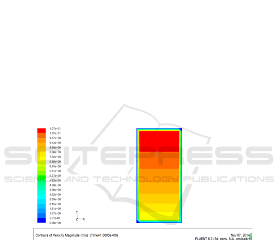
We select several observation points at the plane
hub height of the wind speed entrance to further
measure the wind speed values corresponding to the
different time points, as shown in Fig. 3 to Fig. 7 for
the wind speed inlet plane observations of 1s, 3s, 5s,
10s and 11s. It can be observed from the figure that
the wind velocity values corresponding to the
different moments coincide with the theoretical
curves of the wind speed variation of the hub height
and wind speed of the extreme wind speed inlet
shown in FIG. 8.
Figure 3 (ECG) wind velocity at t = 1s entrance velocity cloud
ICECTT 2018 - 3rd International Conference on Electromechanical Control Technology and Transportation
280
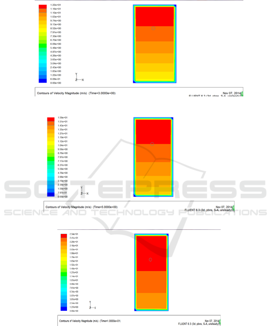
Figure 4 (ECG) wind velocity at t = 3s entrance velocity cloud
Figure 5 (ECG) wind velocity at t = 5s entrance velocity cloud
Figure 6 (ECG) wind velocity at t = 10s entrance velocity cloud
Study of the Establishment of Typical Wind Speed Model Based on Numerical Simulation
281
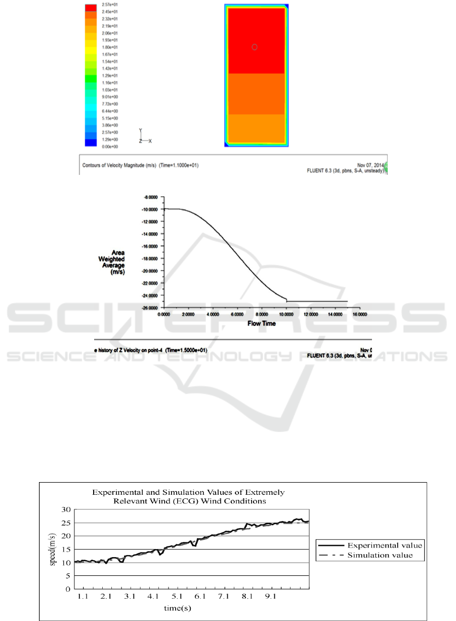
Figure 7 (ECG) wind velocity at t = 11s entrance velocity cloud
Figure 8 hub height wind speed inlet plane wind simulation curve
Our experimental setup for extremely rugged
gust experiments, with one low-power blower for the
main equipment, is highly adjustable. Axial flows
fan, a wind pressure instrument. Axial fans which
can rotate around a small power fan angle of 360
degrees. We conducted experiments on extreme gust
wind speeds by simulating different wind speeds at
the same angle with an axial fan and measured the
wind speed at the hub of the small fan by a wind
pressure gauge. The experimental results of the
extreme gust wind speed are obtained and compared
with the simulation values. The comparison results
are shown in Figure 9, and the two curves are
basically fitted. Therefore, the correctness of the
simulation of the extreme gust wind speed is also
verified.
Figure 9 Experimental and simulated values of extreme wind gust (ECG) wind conditions
ICECTT 2018 - 3rd International Conference on Electromechanical Control Technology and Transportation
282

The wind speed model is the focus on this
chapter. In the selection of wind conditions, we
consider the extreme correlation gusts model under
abnormal operating conditions considering the
complicated wind speeds encountered with the
actual operation of the wind turbine, including
formula the derivation, as well as the specific
algorithm compilation process. Through the UDF
interface simulation, the velocity simulation curves
and speed curves of each wind speed model are
obtained. Experimental data are obtained through
the experimental equipment, and compared with the
simulation value to verify the correctness of the
Fluent simulation.
REFERENCES
Wang L, Huang H, Rae W. West Impeller modeling and
analysis based on UG NX / KF and Fluent [J] J. Cent.
South Univ, 2012, 19: 3430-3434.
Rosario L, Stefano M, Michele M. 2D CFD Modeling of
H-Darrieus Wind Turbines Using a Transition
Turbulence Model [J]. Energy Procedia, 2014,
131-140.
Alexandros M, John C. Validation of a CFD model of
wind turbine wakes with terrain effects [J]. Journal of
Wind Engineering and Industrial Aerodynamics, 2013,
124-128.
Lanzafame R, Mauro S, Messina M. Wind turbine CFD
modeling using a correlation-based transitional model
[J]. Renewable Energy, 2013, 31-39
Pope K, Dincer I, Naterer G, Energy and exergy efficiency
comparison horizontal and vertical axis wind turbines
[J]. Renewable Energy, 2010, 35 (9), 2102-2113.
Ma Na, Yuan Qilong, Zhou Xintao, Wang Ben, Li
Yan.Numerical Simulation of Aerodynamic
Characteristics of Wind Turbine Blades [J].Journal of
Mechanical Science and Technology, 2014,236 (10):
1473-1478.
Bontempo R, Manna M. Performance analysis of open and
ducted wind turbines [J]. Applied Energy, 2014:
405-416
Yu Yong, Fluent introductory and advanced tutorial [M].
Beijing: Beijing Institute of Technology Press, 2012:
261
Study of the Establishment of Typical Wind Speed Model Based on Numerical Simulation
283
