
Modelling and Simulation of the Opening Process for the Aircraft
Engine Starter Valve
Yitao Liu, Chao Liu, and Zhenbo Yang
School of Aircraft Maintenance Engineering, Guangzhou Civil Aviation College, Guangzhou, China
liuyitao@caac.net, liuchao@caac.net
Keywords: Engine, Starter Valve, Butterfly Valve, Pneumatic, Modelling, Simulation.
Abstract: The structure and principle of the aircraft engine starter valve with dual pneumatic actuators are introduced.
Characteristics of the valve, in particular the opening behaviours are analysed using mathematical models.
The butterfly valve opening process under different inlet pressure is simulated on AMESim simulation
environment. By comparing with test data, the model is proved to be accurate and reliable. The simulation
results show that inlet pressure plays an important role in the opening process. The variables of primary
interest are the rotating angle and time of the butterfly valve. In the dual actuators architecture, the valve
requires less inlet pressure to rotate the butterfly disc full open and has higher reliability during aircraft
operational cycle.
1 INTRODUCTION
When starting a gas turbine aircraft engine such as
turbojet, turboshaft and turbofan, rotation of the
compressor to a speed is required to provide
sufficient air to the combustion chamber. The
starting system of the engine often utilizes
pressurized air to drive a turbine at high speed. This
turbine applies a torque to the engine high pressure
rotor system through a reduction gear in the (starter)
turbine and through the engine accessory drive
system. The air which is necessary to drive the
starter comes from the built-in auxiliary power unit
(APU) or the second engine or a ground power unit.
In most cases, the first engine needs be started using
the APU or ground pneumatic power unit. Then the
remaining engine(s) can be started using cross-bleed
air from the running engine.
The starter air supply is controlled by a starter
valve, which closes and removes pneumatic power
from the starter when the N2 speed reaches 50
percent. The turbine and reduction gears slow and
the clutch disengages when N2 speed is higher than
50 percent. The starter output shaft then turns with
the gearbox and engine. While the turbine and
reduction gears continue to slow until they stop.
The starter valve usually is a butterfly type,
pneumatically operated and electrically controlled.
The civil industries offer a wide range of pneumatic
valves usually equipped with a spring and driven by
pneumatic-based actuators. There have been many
research and development activities, including
mathematical modelling, numerical simulation and
experimental analysis, are undertaken in order to
design and develop an advanced valve (J.T. Ahn,
2011; F. Danbon, 2000; N. Gulati, 2009; ZHU Su,
2016).
But there is a very limited amount of research on
accurate dynamic modelling of butterfly valve used
on aircraft engine. The airline maintenance records
indicate that typical failure of the starter valve is
abnormal opening, including too small open angle
and too long open time (P. Naseradinmousavi,
2011). This paper conducts an investigation of the
valve behaviour in the opening process. The
influence of the inlet pressure on the open angle and
the open time is emphatically analysed.
2 DESCRIPTION OF THE VALVE
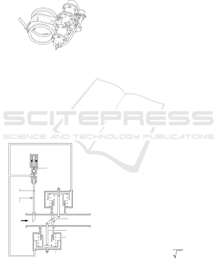
Figure 1 shows a starter valve with dual actuators,
which is a pneumatically operated and electrically
controlled shutoff valve. The valve is composed of
two major sections, the valve flow body section and
the pneumatic actuator and control section. The
valve flow body section consists of the flow body,
butterfly plate shaft, bearings and seals enclosed in
232
Liu, Y., Liu, C. and Yang, Z.
Modelling and Simulation of the Opening Process for the Aircraft Engine Starter Valve.
In 3rd International Conference on Electromechanical Control Technology and Transportation (ICECTT 2018), pages 232-235
ISBN: 978-989-758-312-4
Copyright © 2018 by SCITEPRESS – Science and Technology Publications, Lda. All rights reserved
the valve body. The pneumatic actuators and control
section consist of the controlling solenoid,
diaphragms, torsion closing mechanism, shaft
connecting link, actuating arm and electrical position
indicating switch.
Figure 1: Starter valve.
Figure 2 shows the section schematic of the
starter valve. The valve remains closed with the
solenoid de-energized. Inlet air pressure is routed
through a downstream facing probe and an opening
rate orifice in a chamber solenoid closed by non-
return valve (position shown). The pressure in
opening chambers is vented to ambient through the
solenoid ball and the closing-rate orifice. The
pressure in chambers at opposite position of the
opening chambers is vented to ambient through the
vent orifices. The internal springs of the pneumatic
actuators in combination with the closing torsion
spring force, closes the starter control valve.
Figure 2: Starter valve section schematic.
The starter valve is opened by energizing either
of the solenoid coils. Energizing the solenoid
actuates the solenoid ball to the position opposite
that shown and open the non-return valve. Inlet air
pressure is routed in the opening chambers, then is
sensed on both diaphragms and pistons of the
pneumatic actuators. The pressure increases in the
opening chambers and actuate the pistons when the
pressure is sufficient to overcome the internal
springs and the closing torsion spring. The pistons
actuate to the butterfly open position. The starter air
valve opening rate is controlled by the rate at which
chambers at opposite position of the opening
chambers vents to ambient. These rates are
controlled by the open rating orifice, the purging
orifice and the closing rate orifice.
The valve has a manual override capability
which permits the valve to be opened or closed in
case of failure of the electrical control. The starter
valve is manually opened by rotating the lever
because there is no diaphragm force and pressure in
the pneumatic actuators. The handle can be rotated
against the closing torsion spring to open the
butterfly. When the handle is released, the torsion
spring turns the shaft to the butterfly closed position
and the valve returns to normal operation.
When the butterfly is in any position except
closed, the normally open redundant electrical
position switches provide remote indication. In this
case the switches are actuated by the closing end of
the actuator. The solenoid has two independent coils
including 3 wires wound together (1 active winding
per channel and 1 shunt winding to both active
channels), either one of which when energized will
open the valve. A relief valve is incorporated to limit
the actuator pressure in the event that the inlet
pressure exceeds the normal maximum value.
3 MATHEMATICAL ANALYSIS
3.1 Fluid Mechanics
When air flows through the purging orifice,
opening-rate orifice, closing-rate orifice and the
butterfly valve, as shown in Figure 2, it can be
assumed as isentropic process, and the mass flow
(Q
m
) can be written as (SUN Muqiao, 2012):
u
u
mqm
T
p
CCAQ (1)
Solenoid
Closing-Rate
Orifice
Pneumatic Actuator
Opening-Rate
Orifice
Opening Chamber
Connectin
g
Lin
k
Actuating Arm
Purging
Orifice
Air
Flo
w
Vent
Modelling and Simulation of the Opening Process for the Aircraft Engine Starter Valve
233
where A and
q
C
denote the area and the throttle
coefficient of the flow respectively, p
u
and T
u
are the
pressure and temperature of the upstream air
respectively, and
m
C
is the flow coefficient. The
expression of
m
C
is written as follows:
cr
u
d
g
cr
u
d
u
d
u
d
g
m
p
p
p
R
p
p
p
p
p
p
p
R
C
,
1
2
)1(
2
,
)1(
2
1
1
12
(2)
where
g
R
is ideal gas constant,
is constant
entropy index, p
d
is downstream pressure; and
cr
p
is critical pressure ratio, whose expression is written
as follows:
1
1
2
cr
p (3)
Using their corresponding parameters, Eq. (1) -
(3) can be applied to calculate the mass flow for the
purging orifice, opening-rate orifice, closing-rate
orifice and the butterfly valve, respectively.
3.2 Dynamics
As shown in Figure 2, for the opening and closing
process, the dynamical equation of the piston
assembly in the actuator can be expressed as:
tia
FFFKx
dt
dx
B
dt
xd
m
2
2
(4)
where m and
x
are the mass and the displacement
of the piston assembly respectively, B the damping
coefficient, K the spring stiffness, F
a
the
aerodynamic force, F
i
the internal spring force, and
F
t
the closing torsion spring force.
The connecting link and actuating arm assembly,
as showed in Figure 2, can be seen as the crank-
connecting rod mechanism. Then the relationship
between the displacement of the piston (x) and the
rotating angle of the butterfly disc (θ) can be
expressed as (LI Bin, 2006):
)]2cos1(
4
)cos1[(
L
r
rx (5)
where r and L represent the length of the actuating
arm and the connecting link respectively.
4 AMESIM MODELLING AND
SIMULATION
4.1 Modelling
Based on the previous mathematical modelling
analysis, we select the suitable component from the
AMESim signal library, the machine library and the
gas component design library.
According to the structure principle of Figure 2,
we use three throttle holes to simulate the orifices
respectively.
The displacement (x) of the piston in the actuator
determines the rotating angle (θ) of butterfly disc,
and it can be measured by displacement sensor.
Then we use a function to represent the relationship
between displacement and rotating angle.
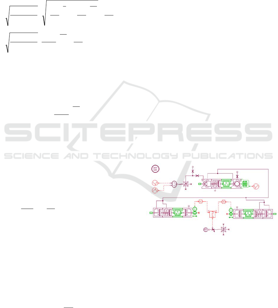
The models of the above parts are connected
according to the schematic diagram of the system.
The function between the displacement of the piston
and the rotating angle of the butterfly disc is set up.
Also, the input pressure and the temperature signal
source are set up. Finally, the whole AMESim
model of the starter valve is created, as shown in
Figue 3.
Figure 3: The AMESim model of the starter valve.
4.2 Simulation and Discussion
As previously mentioned this starter valve often fails
due to too long open time and/or too small open
angle. Therefore our main interest here is the
investigation of the valve behaviour in the opening
process, particularly the open time under different
inlet pressures.
ICECTT 2018 - 3rd International Conference on Electromechanical Control Technology and Transportation
234
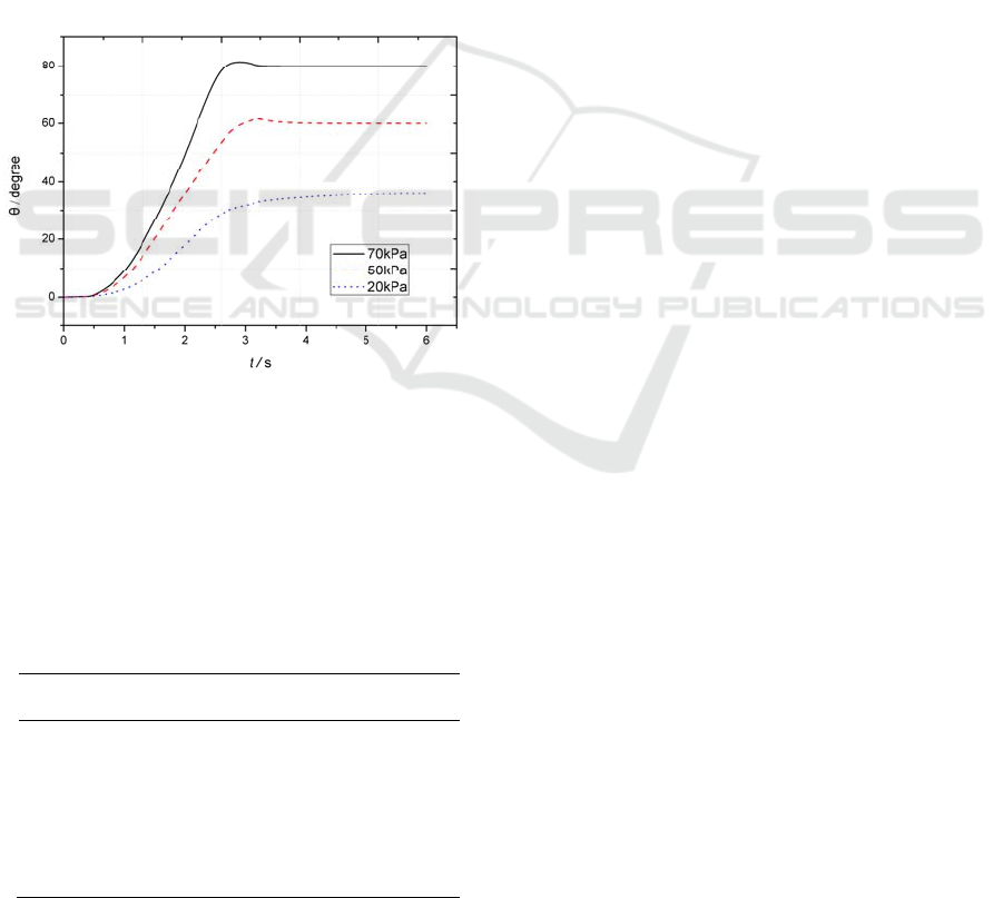
In the opening process, the rotating angle and
time of the valve disc under different inlet pressures
are given in Figure 4. The curves indicate that the
time butterfly disc rotates 80° from full close, seen
as an acceptable full open angle in opening process,
requires less than 3s when the inlet pressure is no
less than 70 kPa. Obviously this dual actuators
architecture allows the actuating mechanism to
produce a high torque to open the valve, compared
with the single actuator valve.
Normally the upstream pressure of the starter
valve is approximately 0.3MPa when engine starting,
largely greater than 70kPa, the minimum full open
pressure. Hence the valve can open successfully
even if it is frozen with ice.
But when the inlet pressure is too low, for
example 20kPa, it is not sufficient to overcome the
internal springs and the closing torsion spring, and
the valve will not open normally.
Figure 4: The open time and open angle of the valve under
different inlet pressures.
Table 1 shows the comparison between
simulation results and test data under inlet pressure
at 70 kPa. It indicates that our model is more
accurate and reliable, and is a valuable reference for
pneumatically operated butterfly valve design.
Table 1: Comparison between simulation results and test
data.
Time
(
s
)
Simulation θ
(
de
g
ree
)
Test θ
(
de
g
ree
)
Error
(
%
)
1 7.2 7.0 2.5
2 48.3 47.2 2.3
3 80.1 82.7 3.2
4 80 82.5 3.1
5 80.1 79.1 2.3
6 80 78.3 2.1
5 CONCLUSIONS
An accurate model for aircraft engine starter valve is
created based on AMESim simulation environment.
The opening process of this butterfly valve is
emphatically investigated. The simulation results are
compared with the test data. The model is proved to
be correct and the simulation system is useful.
The analysis results indicate that the dual
actuators architecture butterfly valve requires less
inlet pressure, produces higher rotating torque, and
provides higher reliability during aircraft operational
cycle. But it is recommended to use the manual
override lever to open the engine starter valve in
severe freezing environment.
REFERENCES
Information on https://www.faa.gov.
J.T. Ahn, K.C. Lee, K.H. Lee, and SH Han, Investigation
of the mechanical behavior of a flexible solid metal
seal for a cryogenic butterfly valve, Journal of
Mechanical Science & Technology, 2011, 25 (9)
:2393-2400.
F. Danbon, C. Solliec, Aerodynamic Torque of a Butterfly
Valve—Influence of an Elbow on the Time-Mean and
Instantaneous Aerodynamic Torque, Journal of Fluids
Engineering, 2000, 122 (2) :337-344.
N. Gulati, E.J. Barth, A Globally Stable, Load-
Independent Pressure Observer for the Servo Control
of Pneumatic Actuators, IEEE/ASME Transactions on
Mechatronics, 2009, 14 (3) :295-306.
ZHU Su, Fault analysis of starter valve on A320 series
aircraft, Aviation Maintenance & Engineering,
2016,1:78-80. (in Chinese)
P. Naseradinmousavi, C. Nataraj, Nonlinear mathematical
modeling of butterfly valves driven by solenoid
actuators, Applied Mathematical Modelling, 2011, 35
(5): 2324-2335.
SUN Muqiao, SU Sanmai,CHENG Jian,SONG Ruitao,
Air turbine starter presure controler modeling and
numerical simulation based on AMESim, Journal of
Aerospace Power, 2012, 27(2):450-456. (in Chinese)
LI Bin,YANG Chunlei, LIU Yong, Analysis on
characteristics of the movement and force of crank-
connecting rod mechanism, Machinery, 2006, 1(33):
10-12. (in Chinese).
Modelling and Simulation of the Opening Process for the Aircraft Engine Starter Valve
235
