
The Hierarchical Control Architecture Design for Cascaded Energy
Storage Power Conversion System
Qingfeng Wang, Junyong Wu, Zicheng Liu, Junchi Li and Fei Xiong
School of Electrical Engineering, Beijing Jiao Tong University, Beijing 100044, China
16121532@bjtu.edu.cn, zcliu@bjtu.edu.cn
Keywords: Power Conversion System, Cascaded Topology, Hierarchical Control.
Abstract: Considering the complexity of the control architecture for the cascaded energy storage power conversion
system (PCS) in high-voltage high-power applications, an improved hierarchical control structure consisted
of three-layer controllers is proposed to achieve required synchronization among different modules and
improve the reliability of the entire system. Firstly, the principle and realization of the three-layer
hierarchical control architecture are illustrated. Further, from top to bottom, each of the three layers is
introduced, and the communication between different layers is analysed. Finally, the proposed structure of
distributed hierarchical control system is verified by a laboratory prototype of 4-cascaded energy storage
PCS, which demonstrates the correctness and validity of the control system.
1 INTRODUCTION
Renewable energy is gaining increasing attention,
because of the lack of the fossil fuels and the
pollution of the environment (Ding, 2013). Due to
the inherent randomness and volatility of the wind
power and solar photovoltaic power generation,
energy storage becomes the key technology for
efficient use of renewable energy (Lin, 2012).
Battery energy storage has occupied a large market
in China because of its traditional mode of use and
mature control technology. In recent years, the grid-
connection research of wind farm combining with
battery energy storage system has become one of the
hotspots in the field of electrical engineering (Gao,
2015; Tian, 2015; Miao,2014; Ai, 2015; Novakovic,
2012).
Due to the limitation of the voltage level and
capacity of a single energy storage converter, most
large-scale energy storage power stations are
connected to the power grid by several transformers
boosting after using multiple single energy storage
converter units in parallel (WU, 2016). This kind of
operation mode not only has the disadvantages of
parallel circuit ring current and transformer loss, but
also increases the cost of building the energy storage
power station. Therefore, the cascaded energy
storage PCS is preferred in high-voltage and high-
power battery energy storage and grid-connected
applications, which can be connected directly to the
10 kV high voltage system without using the
transformers. This cascaded topology is very
convenient to expand the capacity and match the
required voltage grade of power system, which
solving the problems of large-scale battery energy
storage at present, really realizing centralized high-
power energy storage.
However, for this kind of cascade energy storage
PCS, the traditional centralized control has poor
reliability and reconfigurability. Moreover, the
increasing number of cascaded modules resulted in
increasing exchange information between controllers
which deteriorates the difficulty in designing the
control system (Zhao, 2011).
This paper proposes a control architecture, which
has a very good extensibility to cascaded energy
storage PCS with any number of modules. In the
laboratory, the feasibility of the control architecture
is verified by experiments on a prototype of a
cascade high power energy storage PCS.
2 THEORY AND DESIGN OF PCS
Figure 1 shows the topology of the cascaded high-
power energy storage PCS. Each phase cascaded by
216
Wang, Q., Wu, J., Liu, Z., Li, J. and Xiong, F.
The Hierarchical Control Architecture Design for Cascaded Energy Storage Power Conversion System.
In 3rd International Conference on Electromechanical Control Technology and Transportation (ICECTT 2018), pages 216-222
ISBN: 978-989-758-312-4
Copyright © 2018 by SCITEPRESS – Science and Technology Publications, Lda. All rights reserved
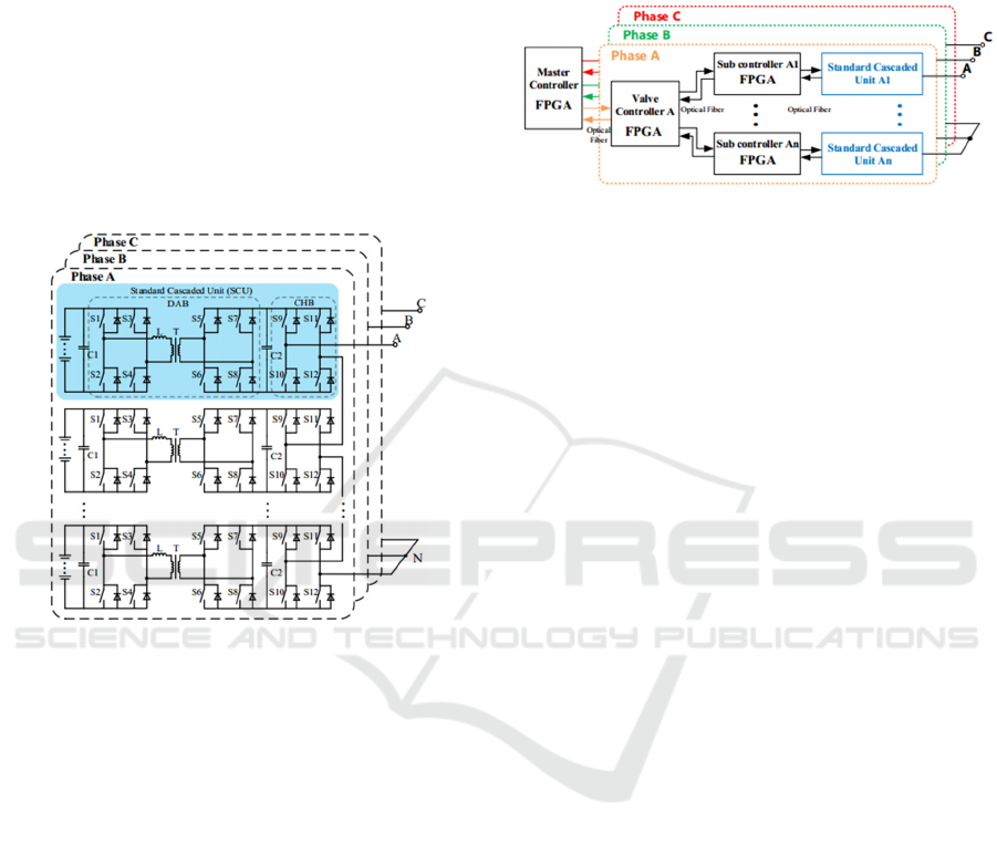
n standard cascade units (SCU) can be connected to
10kV high voltage system directly.
The SCU is composed of battery array,
bidirectional isolated dual-active-bridge (DAB) DC-
DC converter and cascaded H-bridge (CHB) DC-AC
inverter. The power flow direction can be controlled
by DC-DC converter using carrier phase-shift PWM
control (K. Takagi, 2017), and the DC-AC inverter
is easy to realize the decoupling control of the active
and reactive power of the PCS (S. Bifaretti, 2012).
The electrical isolation between the AC power grid
and the low voltage side system is realized by high-
frequency isolated transformers to ensure the safety
of the battery array and personnel (Y. Lee, 2017).
Figure 1: Topology of a cascaded energy storage
conversion system
2.1 Hierarchical Control System
Hardware Architecture
The topology of cascaded energy storage PCS shows
a chain shape in space. When the cascaded energy
storage PSC is used to high-voltage and large-
capacity applications it will occupy large space. In
this case, the traditional centralized control shows
the characteristics of low reliability, but also is not
conducive to the standardization and modularization
of the device (Liu, 2014; Zhu, 2013; Hang, 2006). A
hierarchical three-layer control architecture
proposed by this paper solves the overloaded
calculation burden of master controller, scanty IO
port and the electromagnetic interference (EMI)
between signal lines and so on problems.
This hierarchical three-layer control architecture
includes master controlling layer, valve controlling
layer and sub controlling layer. This architecture has
obvious advantages in the synchronization
performance, transmission delay and control
accuracy, and it facilitates the standardization and
modularization of high-power PCS. Figure 2 shows
the hierarchical three-layer control architecture
proposed in this paper, which is based on cascaded
high-power energy storage PCS.
Figure 2: Block diagram of a hierarchical three-layer
control architecture
The hierarchical three-layer control framework is
a radiated shape in space and its functions are
divided into three layers. Every layer of which is
introduced in detail as follow.
The master control layer: it contains a master
controller consisting of a field programmable gate
array (FPGA), which is mainly responsible for the
control of the whole system. After completing the
sampling of the three-phase voltage and current on
the AC side, the master controller executes the
closed loop algorithm to calculate the PWM signal
of CHB DC/AC converter. The PWM signal is
generated by the comparison of modulation wave
and triangular carrier. After that, master controller
packages PWM signals to packets and sends them to
the valve controller by the method of fiber-based
asynchronous serial communication. Because the
generations of modulation wave and the PWM
signal are in the same master controller FPGA, the
synchronization problem doesn't exist between the
valve controllers in valve control layer. It greatly
reduces the cooperation control complexity of the
valve control layer;
Valve control layer: it is composed of three valve
controllers, corresponding to A, B, C three phases,
each of which manages separately cascaded sub
controllers in one phase. A valve controller consists
of a FPGA. The task of the valve controller is to
make full use of FPGA’s ability of parallel data
processing to allocate the CHB driver signals from
master controller to the corresponding sub
controller. Due to the existence of the valve
controller, the number of cascade ports of the
cascaded energy storage PCS is greatly expanded,
and the number of cascaded SCU expands rapidly,
making it possible that conversion power of the
device reaches the megawatt level;
The Hierarchical Control Architecture Design for Cascaded Energy Storage Power Conversion System
217
Sub control layer: it is made up of 3n sub
controllers which also consists of a FPGA, and each
sub controller corresponds to one SCU. The sub
controller has 4 specific functions. Firstly, achieving
the local control of the DC/DC converter in SCU;
Secondly, generating the PWM signal of DC/AC
inverter in SCU and adding the dead zone; Thirdly,
detecting and uploading the converters work status
and fault information; Fourthly, achieving rapid
local protection.
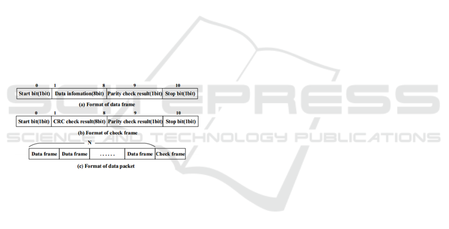
2.2 Interlayer Communication and
Communication Time Delay
Communication between two adjacent layers in this
paper is designed as high-speed fiber-based
asynchronous serial communication. The
transmission of data takes data packet as a unit, each
data packet contains N data frames and 1 check
frame, and the number of data frames N can be set
manually. Therefore, each packet contains (N+1)
frames. Data frame and check frame are composed
of 11 bits, including 1 start bit (0 is valid), 8 data
bits (or a CRC check result bits), 1 parity bit, 1 stop
bit (1 is valid).
Figure 3: Format of data transmission.
High level signal of communication medium
represents no transmission signal, in other words, it
is idle. All frame contains the parity check of the
frame data, the difference is that the check frame
does not contain data information but contains CRC
check result of all data frames in the whole data
packet. The format of two kinds of frames and data
packet is shown as Figure 3. Such a double-check
algorithm with the combination of CRC and parity
check can ensure the accuracy and reliability of
asynchronous serial communication.
Since the communication unit of asynchronous
serial communication is data packet, the packet
sending cycle τ
s
is equivalent to a sampling window
of serial communication. After loading the PWM
signal calculated by controller into the data frames,
controller will assemble the data frames and check
frame into a packet and send it serially every other
sampling window. Due to the data packets that are
sent to different controllers are sent randomly, the
asynchronous serial communication mode can make
communication time delay probably. Considering
the worst communication time delay condition, the
control signal has two levels of communication time
delay from the master controller to the sub
controller, resulting in the maximum communication
time delay between the interphase sub controllers as
a τ
s
. The communication time delay of interphase
sub controllers will lead to unbalanced three-phase
output voltage.
Because the control signals of each of sub
controllers under the same valve controller are from
the same data packet of the valve controller, there is
no communication time delay between the cascaded
SCUs in one phase.
In addition, the switching frequency may have an
impact on the control accuracy of the control system
when the data packet sending cycle is constant,
which will be analysed in detail below.
3 EXPERIMENT AND RESULTS
In the experiment, a hierarchical three-layer control
architecture is applied to the laboratory prototype of
cascaded energy storage PCS. The main controller
calculates the PWM control signal according to the
closed loop algorithm, and divides into three-phase
control signals to the cascaded sub-controllers via
valve controllers. After generating the dead zone,
the sub controllers give out the control pulses to
drive CHBs, and they also complete the control of
DABs. Figure 4 is the photograph of the three-layer
control architecture.
The detailed information of the prototype is as
follows: rated power 6kW; the battery adopts
12V20AH lead-acid battery, and 10 batteries
cascading to one phase, so the rated voltage of the
DC side is 120V; power grid side rated voltage
380V, rated frequency 50Hz; the cascaded SCU
number of one phase is 4; CHB adopts the carrier
phase-shift modulation method and the carrier
frequency is f
c
= 2kHz.
ICECTT 2018 - 3rd International Conference on Electromechanical Control Technology and Transportation
218
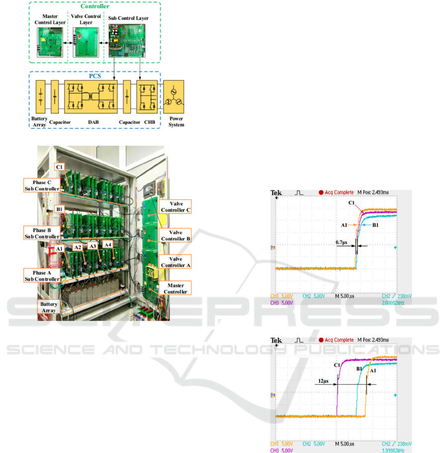
(a) The hierarchical control architecture schematic.
(b) The photograph of the laboratory prototype of
cascaded energy storage PCS.
Figure 4: The photograph of the hierarchical three-layer
control architecture in experiment.
3.1 Control System Time Delay
In order to verify the proposed control system time
delay performance, the master controller sends a
pulse with a duty ration of 0.5 to the cascaded CHBs
of each phase.
Three sets of waveform are collected in
experiment. Figure 5(a) and 5(b) is the output
driving pulses of first sub controller A1, B1, C1 of
the phase A, B, C; The waveforms showed in Figure
6 are the output pulses of four cascade sub
controllers (A1, A2, A3, A4) under the phase A
valve controller, which are sent to the corresponding
CHB upper bridge leg switch S9. Due to the random
of sending packet in asynchronous serial
communication, the communication time delay is
generated randomly. From figure 5(a), the minimum
communication time delay captured by oscilloscope
is approximately 0.7μs, and Figure 5(b) shows that
the maximum communication time delay captured
by oscilloscope is about 12μs.
According to the three-phase imbalance degree
formula (A.1) in national standard GB/T 15543-
2008, we calculated the three-phase voltage
unbalance factors caused by communication time
delay of control system. The three-phase voltage
unbalance factors are ε
u2
=ε
u0
=0.0628%, which fully
complies with the 1.5% requirement of national grid
standard Q/GDW 480-2010.
As shown in Figure 6, the communication time
delay between the 4 cascaded CHBs in the phase A
valve controller is nearly equal to 0, which proves
that there is no communication time delay between
the SCUs in one phase. The experimental results are
in accordance with the analysis in section 2.2.
(a) The smallest interphase communication time delay in
experiment.
(b) The maximum interphase communication time delay in
experiment.
Figure 5: The communication time delay comparison of
interphase SCUs in experiment.
The Hierarchical Control Architecture Design for Cascaded Energy Storage Power Conversion System
219
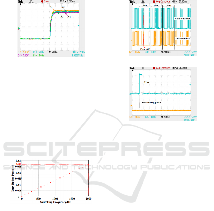
Figure 6: The communication time delay comparison of
in-phase SCUs in experiment.
3.2 Control System Control Precision
Control precision of control system is defined as the
duty ratio's minimum control precision
1/
s
c
P
f
τ
= .
where, P represents the minimum duty ratio control
accuracy that control system can realize. The PWM
pulse exist the possibility of loss, if the duty ratio is
less than P; τ
s
is the data packet sending cycle of
controller; f
c
is the switching frequency.
Figure 7 shows the relationship between the duty
ratio precision P and the switching frequency f
c
when the data packet sending cycle τ
s
is determinate
(in this paper τ
s
=13.3μs).
Figure 7: Relationship between the duty ration precision
and the switching frequency.
The control pulse with 0.02, 0.2 and 0.5 duty
ration was verified respectively in this experiment.
Figure 8(a) is a comparison of the output waveform
of the master controller and the valve controller
when the control pulse duty ratio (D) is 0.02, 0.2 and
0.5 periodically. Figure 8(b) shows the missing pulse
for the partial enlarged figure of Figure 8(a).
(a) Duty cycle precision experiment waveform.
(b) Partial amplification waveform
Figure 8: Duty ratio precision experiment waveform when
f
c
=2kHz.
It can be seen from figure 6 that the control
system minimum duty ratio precision is P=0.026,
when the data packet sending cycle τ
s
=13.3μs, and
f
c
=2kHz. In Figure 8(a), the pulses with 0.02 duty
ratio exist loss, but the control pulses can be
accurately restored when the duty ratio is 0.2 or 0.5.
The theoretical analysis of the foreword is verified.
3.3 Interlayer Communication
In this experiment, we take the communication of
valve controller and submodule controller as an
example and measure the serial information sent by
the valve controller to the sub controller. In order to
identify the format of frame easily, the data in two
adjacent data frames in a data packet is set to “170”
and “85” respectively, corresponding to the 8-bit
binary: "10101010" and "01010101", respectively.
Fully considering the increase of cascade number,
each packet contains 14 data frames + 1 check
frame. The data packet sending cycle τ
s
is set to
τ
s
=13.3μs.
Figure 9(a) is the output information waveform
of the valve controller's transmitting fiber. Figure
9(b) is partial enlarged waveform of a data packet.
ICECTT 2018 - 3rd International Conference on Electromechanical Control Technology and Transportation
220
(a) Valve controller transmit feiber output waveform.
(b) Data frame waveform enlargement
Figure 9: The valve controller asynchronous serial
communication waveform;
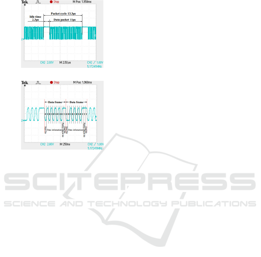
We can see from it that the data packet sending
time is about 11μs, and the idle time is about 2.3μs,
which is consistent with the communication
configuration of the theory. The format of each
frame is clearly visible from it, including 1 start bit,
8 bits of data information (or CRC check bits), 1
parity bit and 1 stop bit, which agreeing with the
communication protocol defined in section 2.2.
4 CONCLUSIONS
In this paper, a hierarchical three-layer control
structure composed of the master controller, valve
controllers and sub controllers is proposed for the
cascaded energy storage PCS. The proposed
heretical control architecture helps to solve the
problems such as the overburden of the master
controller in traditional centralized control mode, the
shortage of IO ports and EMI between signal lines.
Furthermore, it simplifies the complexity of the
coordinated control of multiple controllers,
decreases the difficulty of the control system
hardware and software design, and improves the
communication reliability and the synchronization
performance with satisfying transmission delays and
control precision. Moreover, along with the
characteristics of standardization and
modularization, the SCU has excellent extensibility
to cascaded PCS adapted to different voltage grades
and storage capacity. Therefore, the proposed SCU
is of great significance to the future application of
high-power battery storage.
ACKNOWLEDGEMENTS
This work was partially supported by National
Natural Science Foundation of China under Project
51707007, and China Postdoctoral Science
Foundation under Project 2017M620601.
REFERENCES
M. Ding, Z. Chen, J. Su, Z. Chen, J. Wu and C. Zhu. An
overview of battery energy storage system for
renewable energy generation. Automation of Electric
Power System, 2013, vol. 37, (1), pp. 19-25.
W. Lin, J. Wen, X. Ai, S. Chen and W. Li.Probability
density function of wind power variations .
Proceedings of the CSEE, 2012, vol. 32, (1), pp. 38-
46.
N. Gao, R. Li, Q. Chen and X. Cai. Optimized DC-link
voltage control for double-stage medium frequency
isolated power conversion system. Proceedings of
the CSEE, 2015, vol. 35, (17), pp. 4477-4485.
M. Tian, J. Wu, L. Hao, F. Xiong, J. Zhang and J. Zhang
. The soft starting control strategy on the multi-port
DC/DC converter of battery storage system. Power
System Technology, 2015, vol. 39, (3), pp. 2465-
2471.
Q. Miao, J. Wu, H. Ai, F. Xiong, D. Qi and L. Hao.
Coordinated control of hybrid cascaded megawatt
power regulation device . Electric Power
Automation Equipment, 2014, vol. 34, (7), pp. 43-49
.
H. Ai, J. Wu, L. Hao, B. Feng, J. Zhang and J. Zhang.
Research on battery self-balancing control strategy in
cascade energy storage system . Transactions of
China Electrotechnical Society, 2015, vol. 30, (14),
pp. 442-449.
B. Novakovic and A. Nasiri. Modular Multilevel
Converter for Wind Energy Storage Applications.
2012 IEEE International Electric Vehicle Conference,
pp. 1-7, 4-8 March 2012.
J. WU, D. MEI, J. ZHANG, L. HAO, F. XIONG, H. AI
and Q. MIAO. Technology and Its Application of
MW-Scale Converter in Battery Energy Storage
System. Electric Power Construction, 2016, vol. 37,
(8), pp. 45-51.
The Hierarchical Control Architecture Design for Cascaded Energy Storage Power Conversion System
221

B. Zhao, G. Yu, L. Wang and Y. Xiao. Bi-directional
Extensible Converter and Its Hierarchical Control
Strategy for Battery Energy Storage Grid-connected
System. Proceedings of the CSEE, 2011, vol. 31,
(S1), pp. 244-251.
K. Takagi and H. Fujita. Dynamic Control and
Performance of a Dual-Active-Bridge DC–DC
Converter. IEEE Transactions on Power Electronics,
2017, vol. PP, (99), pp. 1-1.
S. Bifaretti, L. Tarisciotti, A. Watson, P. Zanchetta, A.
Bellini and J. Clare, 2012. Hierarchical commutations
pulse-width modulation technique for high-power
AC/DC multi-level converters. IET Power
Electronics, 2012, vol. 5, (6), pp. 909-919.
Y. Lee, A. J. Watson, G. Vakil and P. W. Wheeler. Design
considerations for a high-power dual active bridge
DC-DC converter with galvanically isolated
transformer. 2017 IEEE Energy Conversion Congress
and Exposition (ECCE), pp. 4531-4537, 1-5 Oct.
2017.
J. Liu, F. Xiao, W. Chen and X. Yang. Switchable fiber
ring net and synchronization method for inverter
hierarchical control. Automation of Electric Power
System, 2014, vol. 38, (3), pp. 89-94.
M. Zhu and R. Zhao. Parallel converter system with high
speed hierarchical main slave control method. Journal
of Zhejiang University: Engineering Science, 2013,
vol. 47, (11), pp. 2031-2037.
L. Hang, H. Hu, Z. Lv and Z. Qian. Novel high speed and
intelligent communication topology based on PEBB
for power electronic system integration. Proceedings
of the CSEE, 2006, vol. 26, (20), pp. 50-56.
ICECTT 2018 - 3rd International Conference on Electromechanical Control Technology and Transportation
222
