
Research on ADRC for Strong Magnetic Resonance Coupling System
Yichen Zhang and Hejin Xiong
School of Automation, Wuhan University of Technology, Wuhan, China
E-mail: 705582225qq.com, 2862696416qq.com
Keywords: Wireless transmission, strong magnetic coupling, ADRC, PID, anti-interference.
Abstract: Aiming at strong magnetic resonance coupling system(SMRCS), this paper has built the system of wireless
power transmission under the control of the classic PID, and then an ADRC(Active Disturbance Rejection
Control) is designed to replace the traditional PI controller in the system to enhance the anti-jamming
performance and the accuracy of identification.The controller is composed of three parts: tracking
differentiator, extended state observer and nonlinear combination. The simulations of two control system have
been carried out in this paper. The two groups of control methods are analyzed and compared, and the results
of simulation show that the ADRC has the advantages of strong anti-interference ability, high accuracy of
identification, good robustness and simple algorithm.It is suitable for the control of the wireless power
transmission under the strong magnetic resonance coupling system.
1 INTRODUCTION
Wireless transmission technology is a hot topic in the
field of energy transmission in recent years. The
technology of wireless power transmission is mainly
based on inductive mode at this stage. Through the
magnetic field of high frequency to create energy
transfer channel between power supply instrument
and electric appliance, to transmit power in a non-
contact way,Compared with the traditional contact
mode, the non-contact mode is safe, reliable and low
cost (Zhai yuan, 2014). It can overcome the
unfavorable environmental factors and so on. In
recent years, the research on wireless power
transmission in strongly coupled resonant systems
has attracted more and more academic attention. In
the strong magnetic resonance coupled radio power
transmission system, because the two resonant links
are added, the order of the whole system is increased,
and the transmission law of the electric energy is
different from the former electromagnetic induction
(Han Jingqing, 2008).
A wireless transmission system consisting of four
coils is established in the literature, and the output
voltage is adjusted by the traditional PID control to
keep the output signal constant. In order to identify
and control the relative parameters of secondary side
through the primary side, the phase of the voltage and
current of the primary coil is obtained by mutual
inductance model, and the mutual inductance and the
magnitude of the load impedance are obtained. Get
the function relationship between the input voltage to
the output voltage through the related parameter
identification.we construct the Buck converter to
adjust the input voltage.Because the input and output
of Buck converter can be obtained by the relevant
primary side, there is no need to construct other
measuring circuit. It reduces costs and improves
reliability (Bai Mingxia, 2010). In addition, the
traditional PI controller in the system is replaced by
ADRC in this paper. By comparing the output signals,
datas and images after the replacement of the system,
it highlights the better correction and anti-
interference function of the ADRC.
2 THE SMRCS UNDER
TRADITIONAL PI CONTROL
2.1 Proposed technical scheme
A radio energy transmission system under typical
strong magnetic coupling resonant mode consists of 4
coils, one of which is a transmitting coil, one is a
receiving coil, and the other are two resonant coils.
The input signal through the energy conversion, then
converting electrical energy into magnetic energy by
200
Zhang, Y. and Xiong, H.
Research on ADRC for Strong Magnetic Resonance Coupling System.
In 3rd International Conference on Electromechanical Control Technology and Transportation (ICECTT 2018), pages 200-203
ISBN: 978-989-758-312-4
Copyright © 2018 by SCITEPRESS – Science and Technology Publications, Lda. All rights reserved
the transmitting coil .The first resonant coil receives
the converted magnetic energy and transmitted it to
second resonant coils by means of wireless
transmission (Wang Wenhu, 2015). Finally, the
energy of the second resonant coils is received by the
receiving coil and subjected to magnetoelectric
conversion. The magnetic energy is then converted
into electrical energy and transferred to electrical
equipment after adjustment. This is the principle of
strong magnetic coupling resonance (Wang Zhaoan,
2013).
When the mutual inductance, load size and other
variables change between the resonant coils, the
output signal of the system will change accordingly.
The mutual inductance of the resonance coil and the
magnitude of the load can be identified by measuring
the phase between the current and voltage in the
transmitting coil, and other predetermined parameters
can be measured ahead of time (Zhang Xinghui,
2014). The output signal can be controlled by
changing the input signal of the inverter, so as to keep
it stable (Zhu Cheng, 2014). The function of changing
the input signal of the inverter bridge can be achieved
by adjusting the Buck circuit. When the mutual
inductance between coils or transformer load changed
,the constant output voltage of the system can be
realized by reasonably changing the duty cycle of the
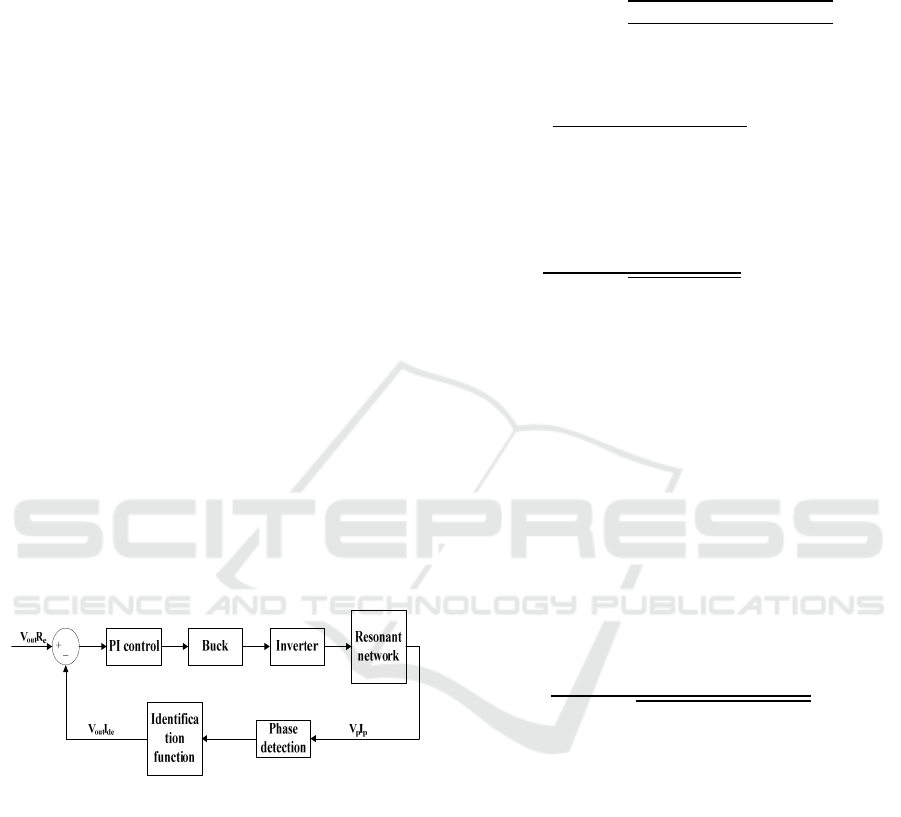
Buck converter. The whole block diagram of the
strong magnetic coupling system is shown in the
following figure (Wang Yu, 2013).
Figure 1: The system structure diagram
2.2 Derivation of output voltage
formula
In the strong magnetic coupling resonance system for
wireless power transmission, when the system
frequency is low, the coil radiation loss resistance Rra
and ohmic loss resistance Rr in the system can be
neglected (Hu Jian, 2014).
It is assumed that the resonant angular frequency
of the system is W0,the transmitter coil current is
Ip, voltage is Vp, the phase between the two angles is
alpha, the time difference between the current and
voltage is △ t, It is assumed that the mutual
inductance between the transmitter and the resonant
coil 1 is Mps, and the mutual inductance between the
receiver and the resonant coil 2 is Mrl.
Mutual inductance between resonant coils can be
derived:
M
sr
=M
rl
M
ps
△
⁄
(1)
The equivalent load impedance can be deduced :
R
ac
=
△
△
⁄
(2)
The input equivalent voltage of the inverter is
assumed to be Vi.The output voltage of the strong
magnetic coupling resonance system is as follows:
V
o
=
(
)
(3)
From the upper model, the mutual inductance
changes between the coils will cause the output
voltage of the strong magnetic coupling resonance
system to change accordingly. On the other hand,
other component parameters can be set as fixed
quantities or derived according to relevant step
detection. When the output voltage of the system is
changed, a BUCK circuit can be set to adjust the
output voltage. By adjusting the duty cycle, the output
voltage is stabilized at a constant value (Liu Keyi,
2014).
Assuming that the duty ratio of the BUCK
converter circuit is D, the expression of the final
output voltage is obtained:
V0=
(
)
(4)
On the basis of the BUCK transform circuit, the
PI controller is added to detect and correct the error
between the actual output voltage and the artificially
given voltage .It can adjust the duty cycle of the
BUCK circuit,to ensure that the actual output voltage
is generally stable at an ideal constant value.
2.3 Experimental study under PI
control
MATLAB is used to build the system simulation
circuit, and a real-time dynamic resistor is added into
the system as the interference signal. When changing
the value of the load or mutual inductance,As can
be seen from the figure below, the PI controller can
basically adjust the duty cycle, so that the output
Research on ADRC for Strong Magnetic Resonance Coupling System
201
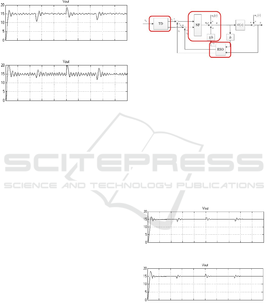
voltage of the system is always stable near a constant
value. But the graphic fluctuation is frequent, and the
system anti-interference ability is poor.
Figure 2: Output voltage waveform when load changes
Figure 3: Output voltage waveform when mutual
inductance is changed
3 THE SMRCS UNDER ADRC
CONTROL
3.1 The basic structure and algorithm
of ADRC
The ADRC is composed of three parts: tracking
differentiator(TD), extended state observer(ESO) and
nonlinear combination(NLC). In ADRC, the
transition process for parameter input is implemented
by TD, which allows for smooth input signals and get
the corresponding differential signals. As the core
part of the ADRC, the ESO is used to reconstruct the
object model by double channel compensation, which
makes the uncertain and nonlinear system
deterministic and linearized (Liu Keyi, 2014). By
measuring the controlled object through ESO, both
the values of each state variable and the right side
estimation of the controlled object equation, that is,
the disturbance estimation, can be measured. Take the
output of TD and the state variable given by ESO,
estimate the error between them, and get the error of
the state variable.
3.2 Design of ADRC
The block diagram of ADRC is shown in the
following figure. G (s) is the whole transfer function
of the strong magnetic coupling resonance system.
Adjust the related parameters and components of
the ADRC simulation circuit, add it to the system and
replace the PI controller in the original system after
encapsulation.
Figure 4: ADRC block diagram
3.3 Experimental study of ADRC
The parameters of the simulation circuit and ADRC
are adjusted(Bagus Manhawan, 2000). When the
parameters of the system are basically stable and able
to work properly , Through the control variable
method, the parameter identification under the load
change and mutual inductance change are studied
respectively.Make sure that changes are consistent
with the changes in traditional PI controls (B C KUO,
1989).
When changing the value of the load or mutual
inductance,as can be seen from the figure below, the
ADRC can basically adjust the duty cycle, so that the
output voltage of the system is always stable near a
constant value. And the graphic fluctuations are
basically eliminated. The system anti-interference
ability also be better.
Figure 5: Output voltage waveform when load changes
Figure 6: Output voltage waveform when mutual
inductance is changed
ICECTT 2018 - 3rd International Conference on Electromechanical Control Technology and Transportation
202

4 COMPARISON OF PID
CONTROL AND ADRC
The experimental results show that the strong
magnetic coupling resonance system with ADRC has
the following characteristics as compared with the
traditional PID controller.
1. When the load or mutual inductance of the
system changes, the feedback detection mechanism in
the system can detect this change by the phase angle
of the coil voltage and current. The two controllers
can complete the corresponding parameter
identification. But the system parameter
identification under ADRC is more accurate and
closer to the actual given value.
2. When the system related parameters are
changed, the output voltage of system is calculated
by the controller, and it is always stabilized near a
constant value by changing the duty ratio of the
BUCK circuit. The two controllers can basically
complete the correction function. But the output
voltage fluctuation of the system under traditional
PID controller is larger. The output fluctuation of the
system under ADRC is smaller, and it has stronger
anti-interference ability.
3. The amplitude and overshoot of output voltage
fluctuation with ADRC are smaller . It can be seen
from the following table.
Table 1: Comparison of load changes
Maximum
amplitude /V
Overshoot /%
PID 18.1 20.7
ADRC 16.4 9.3
Table 2: Comparison of mutual inductance changes
Maximum
amplitude /V
Overshoot /%
PID 23.1 30.3
ADRC 17.7 18
Through the comparison, the ADRC can not only
realize the correction and adjustment function of the
traditional PID controller, but also make the system
have better identification function and stronger anti-
interference ability. It has the function of optimizing
the system.
5 CONCLUSIONS
In this paper, the wireless power transmission of a
strong magnetic coupling system under the control of
ADRC is studied.And it is compared in detail with the
results of a same system under the control of the
traditional PID controller.To prove that compared
with the traditional PID controller, it has better
correction function and anti-interference ability. In
the experimental research, the ADRC algorithm is
added, and the traditional PID controller is replaced
by the ADRC. It greatly improves the parameter
identification ability of system, and the identification
result is more accurate. It can eliminate the output
voltage fluctuations caused by the disturbance, so that
the system output voltage remained stable.
REFERENCES
Zhai yuan, Sun Yue, Dai Xin, Su Yugang, Wang Zhihui.
Parameter identification and original side control of
strong magnetic coupling resonance system [J].
proceedings of the world machine and control, 2014,18
(10): 1-6.
Han Jingqing. Active disturbance rejection control
technology. National Defense Industry Press, [M].2008
Bai Mingxia, Huang Zhao. Historical development and
application of wireless power transmission [J]. Journal
of XiangNan University, 2010, (05): 51-53.
Wang Wenhu. Simulation Research on topological
structure of radio energy transmission system [J].
Internet paper library, 2015
Wang Zhaoan, Liu Jinjun. Power electronics technology,
[M]. Mechanical Industry Press, 2013
Zhang Xinghui, Wu Hongbo, Wang Zhaoliang. MMC
circulating suppressor based on active disturbance
rejection control [J]. electric power construction, 2014,
(11): 97-101.
Zhu Cheng, Chen Ji, Jiang Changsheng. Attitude auto
disturbance rejection control of vertical launching
interceptor missile based on four element [J]. Electro
Optics and control, 2014, (05): 6-10.
Wang Yu, Wang Yongliang, Li Jing, et al. Research on
control method of networked servo system [J].
computer disk software and application, 2013, (14): 95-
97.
Hu Jian, Yan Gang Feng. ADRC algorithm of two wheeled
self balancing vehicle based on [J]. analysis of
mechanical and electrical engineering, 2014, (02): 159-
164.
Liu Keyi. Research on parallel predictive control
technology of circulating fluidized bed boiler [D].
Zhengzhou University, 2014.
Bagus Manhawan,Zheng-Hua Luo,Jing-Qing Han,et
al.High-speed High-precision Moton Control of Robots
Using Extended state Obseyver.Journal of the
Robotions Society of Japen.2000,18(20):86-93.
B C KUO. Automatic Control System[M].London:Prentice
Hall,1989.
Research on ADRC for Strong Magnetic Resonance Coupling System
203
