
An Inverse Perspective Mapping Approach using Monocular Camera of
Pepper Humanoid Robot to Determine the Position of
Other Moving Robot in Plane
M. Hassan Tanveer and Antonio Sgorbissa
Department of Bio-Robotics and Intelligent Systems (DIBRIS), University of Genova, 16145 Genova, Italy
Keywords:
Pepper Humanoid Robot, Inverse Perspective Mapping, Monocular Camera, Moving Robot.
Abstract:
This article presents a method to know the position of object or moving robot in the plane while the camera
is moving dynamically. An Inverse Perspective mapping (IPM) approach has been embedded in a monocular
camera on Head of Pepper Humanoid Robot (Softbank Robotics) for real time position determination of other
object or robot in plane. While the Pepper head is moving, it is difficult to determine position or distance to
objects in front of the robot with any different degree of certainity. By applying IPM, a linear relationship
between the IPM frame and world frame becomes the key element to know the position of object while the
head is static but when the head orientation changes the IPM is modified to adapt the linear relationship
between both frames. So, the proposed method is based on the extraction of accurate bird’s-eye view. The
method includes the Image Acquistion, IPM Filtering, Detection Phase, Region of Interest Selection and Pixel
remapping.
1 INTRODUCTION
One of the core elements in field robotic research is
to implement the social robot’s algorithm, that help
robots to anticipate the desired task which results the
ease for humans. In the twentieth century, the process
took place and steps have been put forward for the
realization of fully autonomous humanoid robots (Si-
ciliano and Khatib, 2016). In this domain of robotics,
the problem of position estimation and distance de-
termination has been one of the concered domain be-
cause it can overcome the destruction in robots due to
collision (Lemaignan et al., 2017).
Collision detection systems can provide robots
with an alert prior to a collision that allows robot to
take preventive actions (Stein et al., 2017). The robot
processes can be included in the security system as
mentioned in (Maurino et al., 2017) which immedi-
ately stops the robot processes if an imminent object
is detected in surroundings nearby. In addition, deter-
mining distance within robots, could also allows the
robot to provide alert and to make cautiously com-
ments to the user (Rubenstein et al., 2014). Instruc-
tions may move to prevent this problem, or create a
security setting for sudden collision (Mukhtar et al.,
2015). Many distance determination activities have
been carried out using functional systems such as op-
tical cameras that contributes to greater power and in-
tervention in comparison with optical camera sensors
(Hiremath et al., 2014). For a very simple idea it is
used: Signals used from antenna indicate the purpose
of the target goal. Distance and tags can be calculated
depending on the length of travel and destination.
A robot should detect the relative position of an-
other robot, while the other robot is in the floor. A
large amount of research has been done for distance
determination to an object using forward facing cam-
eras (Tuohy et al., 2010), sonar and laser scanners that
could not be specifically used if the height of other
robot is too low. A multi-camera setup as employed
by (Ma et al., 2014), provides depth information by
establishing feature correspondence and performing
triangulation. However, it also carries severe process-
ing and configuration overheads, which is cheaper and
is not required on power robots.
In this article, openCV tools has been used to
make a blob of color so the specific color object can
be detected by camera and term as a potential ob-
ject. Concurrently, two robots has been adopted Pep-
per Humanoid robot and iRobot Roomba. The Pep-
per robot has capabilities for vision which include fa-
cial and shape recognition (in-built cameras). Sec-
ondly, the iRobot Roomba is a unicycle mobile robot
that performs a wide range of task from autonomous
Tanveer, M. and Sgorbissa, A.
An Inverse Perspective Mapping Approach using Monocular Camera of Pepper Humanoid Robot to Determine the Position of Other Moving Robot in Plane.
DOI: 10.5220/0006930002190225
In Proceedings of the 15th International Conference on Informatics in Control, Automation and Robotics (ICINCO 2018) - Volume 2, pages 219-225
ISBN: 978-989-758-321-6
Copyright © 2018 by SCITEPRESS – Science and Technology Publications, Lda. All rights reserved
219
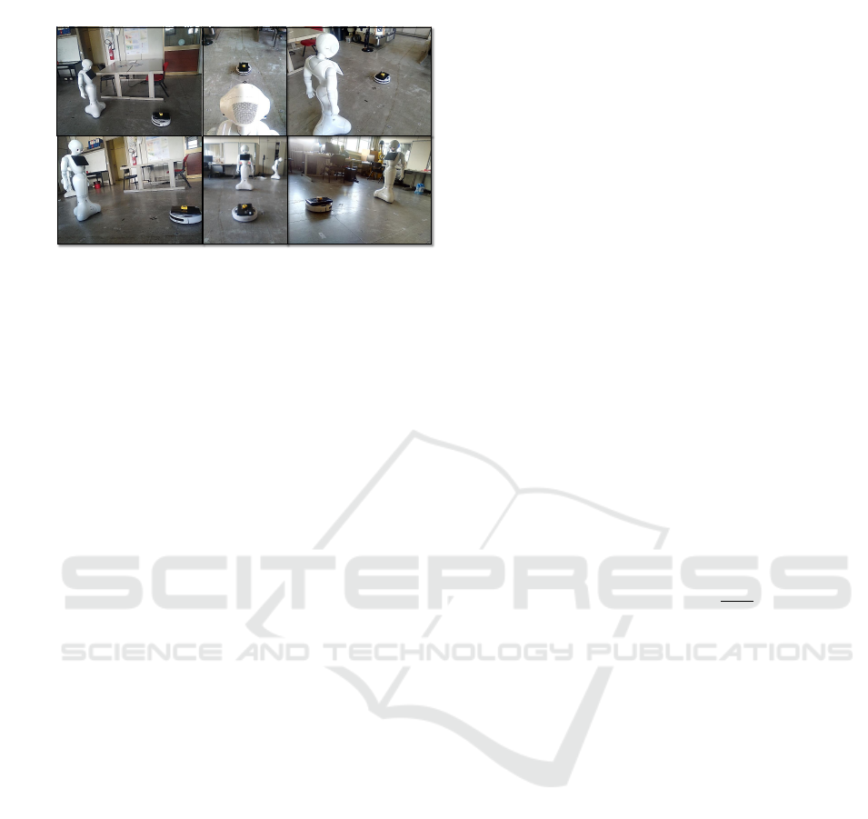
Figure 1: Pepper Tracking other robot in plane.
cleaning and surveillance, to transportation and as-
sistance to the elderly. By combining both of these
robots with potential object, a solution that consists
in the composition of a IPM view (bird’s eye view)
of Pepper head camera has been proposed. This view
will serve as a virtual map for the iRobot Roomba
in the Pepper Frame of view (FOV) to help the user
to adequately specify the commands to be sent to the
other Roomba under its control, as in Fig. 1 that is
referred to Pepper Frame of view. The proposed sys-
tem consists of a single forward facing Pepper cam-
era, capturing video images at 30 frames per second
(fps).
Section II of this paper discusses the Methodology
for distance determination that includes Inverse Per-
spective Mapping which allows the image perspective
to be linearised, the surface subtraction requirement
for object detection and the calibration issues. The
technological platform with discussion of results are
described in section III. Future work concludes the
paper in section IV.
2 METHODOLOGY
The workflow for the process of calculating object po-
sition in moving Pepper Head mainly includes three
parts: IPM Filtering: (Image Acquisition, Grayscale
conversion and Camera Parameter definition), Detec-
tion Phase:(ROI selection and Pixel Remap) and Cal-
culation steps.
The transformation of the coordination system
can be done in a mathematical way using the in-
verse perspective mapping (IPM) that converts pic-
ture coordinates from one point to another (Jeong
and Kim, 2016). The final homogeneous distribution
of the two-dimensional image (input) information in
the pixels changes mainly through the IPM-based re-
moval perspective effect.
Objectively, IPM transformation requires a special
acquisition conditions (i.e:camera location, orienta-
tion, optics, etc.) (Laganiere, 2000) (Lin and Wang,
2012) and some of the assumptions in which the im-
age is presented(here defined as a priori knowledge).
Therefore, the IPM transform can be used in a struc-
tural environment in which, for example, the camera
is placed in a static position or in situations where
the caliber system and caliber can be obtained from
another type of sensor (Yenikaya et al., 2013) (Guo
et al., 2014) (Civera et al., 2008).
In this case, we use the IPM to get a Pepper robot
top-down view from the camera. This change thus
eliminates the non-linearity of the distances between
the frame and the object in the world. Using IPM, the
aim is to map pixel points (u, v) to world coordinate
points (X
w
, Y
w
, Z
w
), as in Eq. 1. The requirement of a
rotation about θ, a translation along the cameras opti-
cal axis, and a scaling by the camera parameter matrix
(Oliveira et al., 2015), can be expressed as:
(u, v, 1)
T
= KT R(x, y, z, 1)
T
(1)
R =
1 0 0 0
0 cosθ −sin θ 0
0 sinθ cosθ 0
0 0 0 1
(2)
T =
1 0 0 0
0 1 0 0
0 0 1 −
h
sinθ
0 0 0 1
(3)
The intrinsic parameters of the camera are represented
by the following matrix:
K =
f ∗ ku s u
0
0
0 f ∗ kv v
0
0
0 0 1 0
(4)
where h is the height of camera, f correspond to the
focal length measured in horizontal and vertical pixel
units k
u
and k
v
respectively. The positions u
0
, v
0
are
the principal points where the optical axis fixes the
image plane.
The camera makes a projection of the 3D view
point in the world with a picture located on a retina
plane. By using a homogeneous coordinate, the pro-
jective connection between 3D light and its image
points can be changed as:
u
i
(v
i
)
1
=
M
11
M
12
M
13
M
14
M
21
M
22
M
23
M
24
M
31
M
32
M
33
M
34
X
w
Y
w
Z
w
1
(5)
The 3 * 4 matrix M
i, j
is the transformation matrix in
Eq. 5. It relates world points to image points accord-
ing to the camera location with respect to the refer-
ence frame, represented by a camera matrix K Eq. 4,
ICINCO 2018 - 15th International Conference on Informatics in Control, Automation and Robotics
220

rotation matrix R Eq. 2 and a translation vector T Eq.
3. If the structure under observation is a plane, it may
be simpler to create because the global coordination
system can be anywhere, it can be conveniently lo-
cated on the plane so it has zero coordinate line Z.
This choice would reduce the projection matrix to:
u
i
(v
i
)
1
=
M
11
M
12
M
13
M
21
M
22
M
23
M
31
M
32
M
33
X
w
(Y
w
)
1
(6)
The updated change focuses on a plane of the world
into the points of the image as well as a source image
may be rewritten as:
dst(u, v) = src(
M
11
X
W
+ M
12
Y
W
+ M
13
M
31
X
W
+ M
32
Y
W
+ M
33
,
M
21
X
W
+ M
22
Y
W
+ M
23
M
31
X
W
+ M
32
Y
W
+ M
33
)
(7)
The sampling rate in X direction at this point is simply
the number of source image pixels between (X,Y, 1)
T
and the point (X + (δX, Y, 1)
T
) divided by the dis-
tance between these two points. The transformation
depends upon the Eq. 6 and can be warped to its dst
coordinates as mentioned in Eq. 7 .
In detection phase, there are conventional tech-
niques that needs the prior knowledge of the object
for detecting it with a camera (Wang, 2013). How-
ever, a more effective approach is used to adopt an
algorithm for Surface Subtraction (SS). The object to
be detected is green in color and wheeled robot has a
small green object on top, and thus the surface sub-
traction algorithm starts from the detection of green
object. Considering the scene in Fig. 2, the object
we must detect is deemed to be the nearest part of
the object in image that is in surface and directly in
front of the Pepper. Therefore the easiest way to ac-
curately detect the object is by accurately setting the
BGR points of potential object, as stated in steps be-
low:
1. Green channel is separated to its constituent in the
BGR image.
2. Taking Green channel into account, the algorithm
calculates the average pixel values in x and y axes
in the captured Pepper image.
3. The algorithm makes a rectangle over the green
object and place a red dot at the bottom center
of the rectangle to calculate the exact pixel value
which is near to the Pepper.
4. The algorithm repeats steps 2 and 3.
From the above mentioned steps the adaptation is
easy under various brightness and surface conditions.
By using the OpenCV morphology tool we get the
green object found under different conditions in light,
because the BGR channel range can be solved man-
ually. Therefore, under the conditions of light, the
result will remain similar to the presence of a green
color due to the upper and lower limits of the BGR
morphological tool. It can help identify potential ob-
jects by recognizing their colors in varying sizes so
that there will be no disruptions under various light-
ing conditions.
Before we calculate the distance between object
and Pepper, we need to calculate the height of the
pixel object from below the image, as done in Fig.
2. From the bottom of the binary image in each RGB
color space, we calculate the average pixel intensity
on each pixel line in the image. From this we find
out how high the object lies in the world frame. The
ground just before Pepper is considered. This is to
minimize the ease of knowing the wrong positives
caused by other things within the Pepper frame.
In previous steps, the pixel points of the potential
object measured by the image are known, but to cal-
culate it according to the global framework, the cali-
bration tool should be a reasonable unit of measure-
ment (i.e there is a lot of calibration methods, such as
(Boyle et al., 2000) (Munaro et al., 2016).
The methods like chessboard calibration and
marking points calibration discussed in (Miraldo and
Araujo, 2013), (Moreno and Taubin, 2012) can be
used as well but in this case, the proposed system
would be implemented with a Pepper camera in a
fixed or moving position. The placement of a green,
blue or red color box with known distance (i.e: known
x and y axes distance) in the FOV of the camera, along
a flat surface, would allow for the measurement of the
number of pixels equivalent to distance. Using this
value, the number of pixels in the image could be con-
verted to a real world value in meters.
3 RESULTS AND DISCUSSION
The algorithm presented here is implemented to Pep-
per Robot in real time to know the position of other
object in plane. For this purpose, the Python lan-
guage, complemented by the OpenCV library of func-
tions was chosen for implementation that allows the
rapid development of image processing algorithms
without the need to develop complex algorithms by
using its open source library of functions (Van der
Walt et al., 2014).
With Pepper robot, a database of video samples
was captured at 30 frames per second (fps), at a reso-
lution of 320*240 pixels. Considering that the change
in distance of potential objects is relatively slow com-
pared to the full frame rate of the system, a slower
An Inverse Perspective Mapping Approach using Monocular Camera of Pepper Humanoid Robot to Determine the Position of Other
Moving Robot in Plane
221
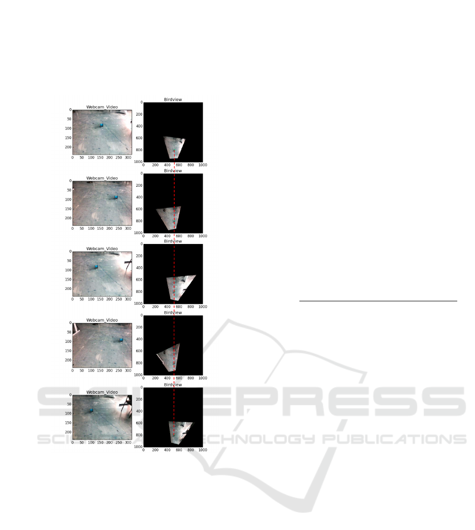
Figure 2: Fixed object IPM view with different Pepper Head
Orientation (i.e: (yaw,pitch) = (36,0),(36,-10),(36,10),(36,-
20),(36,20)).
frame rate was considered for the purposes of calcu-
lating distance and computing position. Using a sam-
pling rate of every 10 frames produced smooth and
reliable results. A frame rate of 10 per second was
chosen as it provides a good trade-off between com-
putation time and number of calculations per second.
The first experiment has been done by putting a
green object at one point in the Frame of view (FOV)
of Pepper Head camera. First it is placed at 0.3m
on X
axis
and 1.8m on Y
axis
, then the data have been
recorded for 300 samples. Then the Pepper head
changes its orientation in different Yaw and Pitch as
shown in Fig. 2. The same acquisition has been per-
formed to other different points, it can be seen from
Figs. 5, 6 that is actual calculation of one point along
x and y axis. The deviation at different Pitch and Yaw
angles are presented in same figure.
It can be seen in bird’s-view image, Fig. 2, that
the relationship between the potential object and its
distance from the camera is linear in nature. However,
the change in the position of the pixel of object will
proportionally reflect this difference in distance. In
order to determine the position of potential object in
bird eye view, the calibration with different distance
on pixels is considered and sum up in a formula as in
Eq. 8 and average error in Eq. 9. It goes something
like: we first calibrate the world points in Bird eye
view frame with a known distance of object. Then the
object is being placed at some distance from Pepper
camera and by measuring at the same time the pixel
(in bird’s-view) corresponding to the object detection.
The apparent pixels is measured corresponding to the
detected object.
i
n+1
= o + p
n
+ i
n
+ noise
(8)
where i is frame point, o is the offset, p is the pixel.
|e
k
| =
q
(x
odometry
− x
IPM
)
2
+ (y
odometry
− y
IPM
)
2
(9)
where x
odometry
, y
odometry
are the reference odometry
points in world frame and x
IPM
, y
IPM
are the achieved
points. The average error and standard deviation of
average error are calculated and denoted by av|ek| and
std |ek|.
The image has been taken with different angles of
Pitch and Yaw by putting the object at one static po-
sition. The clearity of IPM view can be seen in Fig.
2 that due to proposed method the object always im-
plies the same position in IPM view while the camera
is moving. The linear straight red line in Fig. 2 shows
that the head moving has no impact on the position of
object in IPM frame, so it can be converted next to its
respective world frame value.
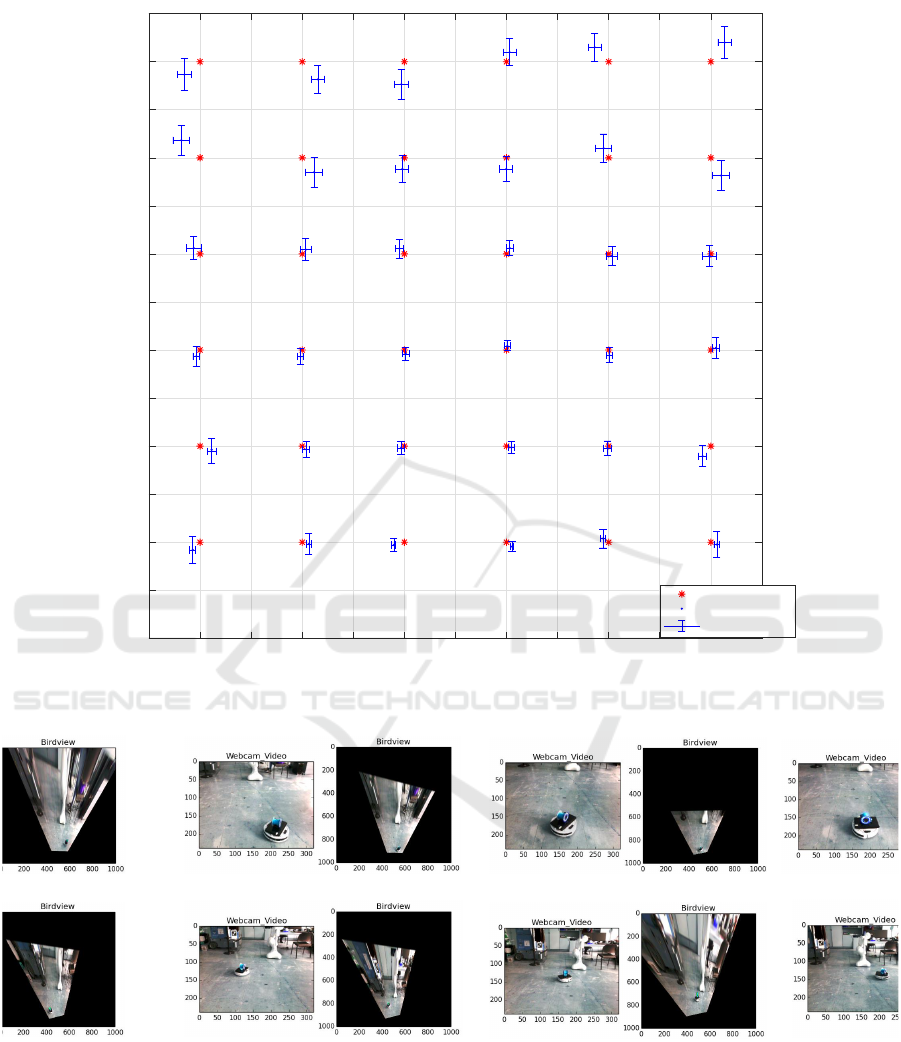
So, for covering the whole plane region of 3.6*3.6
m area, in order to know the object position a total
number of 36 points with 0.6m apart in both axis has
been considered. The red star point in Fig. 3 is the ac-
tual point of the floor and the blue dot is the average
error of all points. The standard deviation of average
error is expressed by error bar of x and y. The num-
ber below each red dot is the number of acquisitions
performed with different values of pitch and yaw.
Specifically the next test is being done by putting
the object 0.6m apart in X
axis
and Y
axis
direction to
check the effective of algorithm in far points. The
results of all points are shown in Fig. 3. The data
recording of each camera angle is being done in
Pitch= 36 to 15 and Yaw= -20 to 20 with 5 intervals
each that in total becomes 45 values for calculating
one point in the best case. The more the object is
closer to the centre of the area, the more will be the
number of recording, since the object will be always
in the FOV of the camera, with all different values
ICINCO 2018 - 15th International Conference on Informatics in Control, Automation and Robotics
222
-1.8 -1.5 -1.2 -0.9 -0.6 -0.3 0 0.3 0.6 0.9 1.2 1.5 1.8
X-axis
meter
0
0.3
0.6
0.9
1.2
1.5
1.8
2.1
2.4
2.7
3
3.3
3.6
3.9
Y-axis
meter
18 15 618156
36 28 836288
45 30 10453010
36 30 10363010
36 28 836288
18 10 618106
Actual point
Average IPM point
Std
avg IPM
Figure 3: IPM Frame of floor (average |av| and std|av|).
Figure 4: Moving robot in Pepper Monocular camera view and IPM Birdeye-view making a circular path.
of pitch and yaw. On the other side, when the ob-
ject is closer to the border of the considered area, it
will be detected by the camera only with a limited set
of pitch-yaw values, thus having a greater number of
recording gives less the error deviation. The region in
between 1.2m to 3m in Y
axis
(i.e: Pitch Movement) has
got almost maximum number of camera view points
which gives the less error rate. The values which are
far away from 3m, they give more deviation because
the far the object goes the Monocular camera becomes
blur which becomes hard to detect the potential ob-
ject, but still it is detecting with low number of Cam-
era point values of Yaw and Pitch. In a similar man-
ner, the deviation in X
axis
is increasing if it rotate Head
An Inverse Perspective Mapping Approach using Monocular Camera of Pepper Humanoid Robot to Determine the Position of Other
Moving Robot in Plane
223
-20 -15 -10 -5 0 5 10 15 20
Yaw angle
degree
0.25
0.26
0.27
0.28
0.29
0.30
0.31
0.32
0.33
0.34
X
meter
Pitch = 36 degree
Pitch = 30 degree
Pitch = 25 degree
Pitch = 20 degree
Pitch = 15 degree
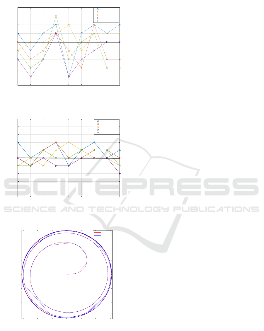
Figure 5: X
axis
-IPM view with different Pepper Head Ori-
entation.
-20 -15 -10 -5 0 5 10 15 20
Yaw angle
degree
1.65
1.68
1.71
1.74
1.77
1.8
1.83
1.86
1.89
1.92
1.95
Y
meter
Pitch= 36 degree
Pitch= 30 degree
Pitch= 25 degree
Pitch= 20 degree
Pitch= 15 degree
Figure 6: Y
axis
-IPM view with different Pepper Head Orien-
tation.
-0.6 -0.4 -0.2 0 0.2 0.4 0.6
X
axis
[m]
-0.6
-0.4
-0.2
0
0.2
0.4
0.6
Y
axis
[m]
Odometry
IPM VIew
Figure 7: Response of IPM view in a circular path.
more than -1.2m to 1.2m in Yaw Orientation. Appar-
ently, the total calculated area of the floor in a grid
form has the capability to tell the position of object in
the plan with a deviation of 0.02m to 0.1m.
While the potential object was placed at differ-
ent points in plane then the corresponding IPM frame
value is being calculated by changing the orientation
of Pepper Head in Yaw and Pitch. In Figs. 5 and 6 it
can clearly be seen that by changing head orientaion
the actual point is 0.3m in X
axis
and 1.8m in Y
axis
as
per world frame but the average error in both figure is
almost very near to actual values. The average error
is due to the camera lens, but it is almost negligible.
The WR has been considered that adopts the path
following algorithm as mentioned in (Morro et al.,
2011). Fig. 4, validates the Pepper camera and IPM
view that shows while the robot is moving in a circular
path, the WR position is being calculated depending
upon the potential objected tracked that is mounted on
the top of roomba.
The Pepper IPM view response while tracking the
odometry of Roomba is shown in Fig. 7, further Eq.
9 is used to calculate the average error, that is av|e| =
0.102m.
4 CONCLUSION
This article presents an efficient collaboration method
in real-time for Pepper Humanoid robot to know the
position of other moving robot or object in the plane.
It is mainly based on visual matching and IPM which
gives the linear relationship between IPM frame and
world frame. So, the experimental results prove that
the position of other potential object is known while
the Pepper robot head orientation is static or moving.
It is shown in the results and discussion section that
the more the number of recording pairs (i.e: Yaw,
Pitch) for each point, gives more accurate calcula-
tions. The results validates that it can work efficiently
for the autonomous diverse environment too. In the
future, more detailed plane information and more spe-
cific collision strategies will be worked out to provide
a more practical system.
ACKNOWLEDGMENTS
This work has been supported by the European Com-
mission Horizon2020 Research and Innovation Pro-
gramme under grant agreement No. 737858.
REFERENCES
Boyle, D. P., Gupta, H. V., and Sorooshian, S. (2000).
Toward improved calibration of hydrologic models:
Combining the strengths of manual and automatic
ICINCO 2018 - 15th International Conference on Informatics in Control, Automation and Robotics
224

methods. Water Resources Research, 36(12):3663–
3674.
Civera, J., Davison, A. J., and Montiel, J. M. (2008). Inverse
depth parametrization for monocular slam. IEEE
transactions on robotics, 24(5):932–945.
Guo, C., Meguro, J.-i., Kojima, Y., and Naito, T. (2014).
Automatic lane-level map generation for advanced
driver assistance systems using low-cost sensors. In
Robotics and Automation (ICRA), 2014 IEEE Inter-
national Conference on, pages 3975–3982. IEEE.
Hiremath, S. A., Van Der Heijden, G. W., Van Evert, F. K.,
Stein, A., and Ter Braak, C. J. (2014). Laser range
finder model for autonomous navigation of a robot in
a maize field using a particle filter. Computers and
Electronics in Agriculture, 100:41–50.
Jeong, J. and Kim, A. (2016). Adaptive inverse perspec-
tive mapping for lane map generation with slam. In
Ubiquitous Robots and Ambient Intelligence (URAI),
2016 13th International Conference on, pages 38–41.
IEEE.
Laganiere, R. (2000). Compositing a bird’s eye view mo-
saic. image, 10:3.
Lemaignan, S., Warnier, M., Sisbot, E. A., Clodic, A.,
and Alami, R. (2017). Artificial cognition for social
human–robot interaction: An implementation. Artifi-
cial Intelligence, 247:45–69.
Lin, C.-C. and Wang, M.-S. (2012). A vision based top-
view transformation model for a vehicle parking as-
sistant. Sensors, 12(4):4431–4446.
Ma, L., Yang, X., and Tao, D. (2014). Person re-
identification over camera networks using multi-task
distance metric learning. IEEE Transactions on Im-
age Processing, 23(8):3656–3670.
Maurino, D. E., Reason, J., Johnston, N., and Lee, R. B.
(2017). Beyond aviation human factors: Safety in high
technology systems. Routledge.
Miraldo, P. and Araujo, H. (2013). Calibration of smooth
camera models. IEEE transactions on pattern analysis
and machine intelligence, 35(9):2091–2103.
Moreno, D. and Taubin, G. (2012). Simple, accurate, and
robust projector-camera calibration. In 3D Imaging,
Modeling, Processing, Visualization and Transmis-
sion (3DIMPVT), 2012 Second International Confer-
ence on, pages 464–471. IEEE.
Morro, A., Sgorbissa, A., and Zaccaria, R. (2011). Path fol-
lowing for unicycle robots with an arbitrary path cur-
vature. IEEE Transactions on Robotics, 27(5):1016–
1023.
Mukhtar, A., Xia, L., and Tang, T. B. (2015). Vehicle de-
tection techniques for collision avoidance systems: A
review. IEEE Transactions on Intelligent Transporta-
tion Systems, 16(5):2318–2338.
Munaro, M., Basso, F., and Menegatti, E. (2016).
Openptrack: Open source multi-camera calibration
and people tracking for rgb-d camera networks.
Robotics and Autonomous Systems, 75:525–538.
Oliveira, M., Santos, V., and Sappa, A. D. (2015). Multi-
modal inverse perspective mapping. Information Fu-
sion, 24:108–121.
Rubenstein, M., Cornejo, A., and Nagpal, R. (2014). Pro-
grammable self-assembly in a thousand-robot swarm.
Science, 345(6198):795–799.
Siciliano, B. and Khatib, O. (2016). Springer handbook of
robotics. Springer.
Stein, G., Dagan, E., Mano, O., and Shashua, A. (2017).
Collision warning system. US Patent 9,656,607.
Tuohy, S., O’cualain, D., Jones, E., and Glavin, M. (2010).
Distance determination for an automobile environ-
ment using inverse perspective mapping in opencv.
Van der Walt, S., Sch
¨
onberger, J. L., Nunez-Iglesias, J.,
Boulogne, F., Warner, J. D., Yager, N., Gouillart, E.,
and Yu, T. (2014). scikit-image: image processing in
python. PeerJ, 2:e453.
Wang, X. (2013). Intelligent multi-camera video surveil-
lance: A review. Pattern recognition letters, 34(1):3–
19.
Yenikaya, S., Yenikaya, G., and D
¨
uven, E. (2013). Keep-
ing the vehicle on the road: A survey on on-road lane
detection systems. ACM Computing Surveys (CSUR),
46(1):2.
An Inverse Perspective Mapping Approach using Monocular Camera of Pepper Humanoid Robot to Determine the Position of Other
Moving Robot in Plane
225
