
Dual-polarized Dual-band Mobile 5G Antenna Array
Igor Syrytsin, Shuai Zhang and Gert F. Pedersen
Department of Electronic Systems, Aalborg University, Fredrik Bajers Vej 7, Aalborg, Denmark
Keywords:
Antenna Array, 5G Antenna, Dual-band, Dual-polarized Antenna, Phased Array.
Abstract:
In this paper, a dual-band dual-polarized phased antenna array for 5G mobile terminals is proposed. The array
has a bandwidth of 3.6 GHz and two resonances at 30.5 and 32.8 GHz. The array has a clearance of 2.85 mm
and fed with two ports in simulation to excite the notch and dipole parts of the proposed antenna structure.
Finally, the proposed antenna element is combined into two arrays with different configurations. It is shown
that it is better to use the array of 8 elements than to use two 4-element sub-arrays with orthogonal orientation.
1 INTRODUCTION
In the recent years the research community and the
industry has been working towards standardization
of 5G mm-wave communication system. Because
the bandwidth is a scarce resource at the current fre-
quency bands under 6 GHz it is decided to implement
the 5G mm-wave system in the mm-wave frequency
spectrum (Rappaport et al. 2013). Currently, eleven
candidate bands in the range between 24.25 GHz and
86 GHz have been considered for the 5G mm-wave
communication system (Lee et al. 2018). To combat
the high path loss expected at the mm-wave frequen-
cies antennas with the gain higher than 7 dBi at both
mobile and base stations. However, because the ori-
entation of the mobile terminal is not known, beam-
forming will be implemented in order to achieve spa-
tial coverage requirements (Roh et al. 2014). The spa-
tial performance of the mobile terminal can be char-
acterized by using the metric of coverage efficiency,
which has been first proposed in (Rehman et al. 2012)
and then applied to 5G mobile terminal antennas in
(Helander et al. 2016). Furthermore, in (Nielsen &
Pedersen 2016) it has been shown that in the typ-
ical indoor propagation channel the received power
depends strongly on the polarization of transmitter
and receiver antennas. The measurements has shown
that up to 10 dB difference can be seen between dif-
ferent antenna polarization combinations, but the co-
polarized antenna configurations are not always the
best option for the indoor channel. Thus, a polariza-
tion reconfigurable antenna is required to adapt to the
channel changes and keep the received power at the
highest possible level.
Antenna array with multiple polarizations is pro-
posed in (Hong et al. 2015) for the mm-Wave 5G
mobile terminals. Then, a low-profile antenna solu-
tion with beam-steering capabilities is proposed in in
(Hong et al. 2014). A Vivaldi phased antenna array
performance and it’s user effects are investigated in
(Ojaroudiparchin et al. 2015). In (Hussain et al. 2017)
a compact 4G MIMO antenna is integrated with the
5G mm-wave mobile array. Two different methods in
(Ojaroudiparchin et al. 2016) and (Zhang et al. 2017)
are introduced in order to create a 3D coverage 5G
mm-wave phased antenna array system. Three sub-
arrays mounted on the folded 3D structure are con-
structed in (Ojaroudiparchin et al. 2016). Then, in
(Zhang et al. 2017) a surface wave is efficiently uti-
lized to change the radiation direction of slot array
elements. However, for 5G mm-wave a bandwidth of
at least 1.6 GHz is required. The wideband antenna
array for 5G mobile terminals has been presented in
(Syrytsin et al. 2018). The proposed antenna element
utilizes four modes in order to achieve the wideband
performance. Circular polarized antennas has been
proposed in (Mahmoud & Montaser 2018), (Syrytsin
et al. 2017) and (Shuai Zhang 2018). Furthermore,
polarization reconfigurability and small clearance are
also very important design considerations for 5G mo-
bile antennas.
In this work, a dual-band dual-polarized 5G mo-
bile phased antenna array is presented. The proposed
antenna consists of two co-located antennas which
can operate at the same frequency but radiate with
orthogonal polarizations. The antenna structure is de-
signed for the 5G frequency band of 30.8 to 33.4 GHz.
However, because the 5G frequency bands are not fi-
nally defined yet, it has been chosen to increase the
bandwidth of the antenna by introducing a second res-
Syrytsin, I., Zhang, S. and Pedersen, G.
Dual-polarized Dual-band Mobile 5G Antenna Array.
DOI: 10.5220/0006919403090315
In Proceedings of the 15th International Joint Conference on e-Business and Telecommunications (ICETE 2018) - Volume 1: DCNET, ICE-B, OPTICS, SIGMAP and WINSYS, pages 309-315
ISBN: 978-989-758-319-3
Copyright © 2018 by SCITEPRESS – Science and Technology Publications, Lda. All rights reserved
309
onance. A bandwidth of 3.6 GHz is achieved by both
antennas with the ground plane clearance of 2.85 mm.
The antenna structure can be easily tuned to other
frequency range by changing a number of antenna
structure dimensions. Finally, the performance of the
phased array in two configurations has been investi-
gated. The metrics of the total scan pattern and cov-
erage efficiency have been used to quantify the simu-
lation results.
2 ANTENNA ELEMENT
PERFORMANCE
In this section, the geometry, operation principle, per-
formance and design considerations of the proposed
antenna element will be described. Surface currents,
reflection coefficient and radiation patterns are used
to describe the performance of the antenna element.
2.1 Antenna Geometry
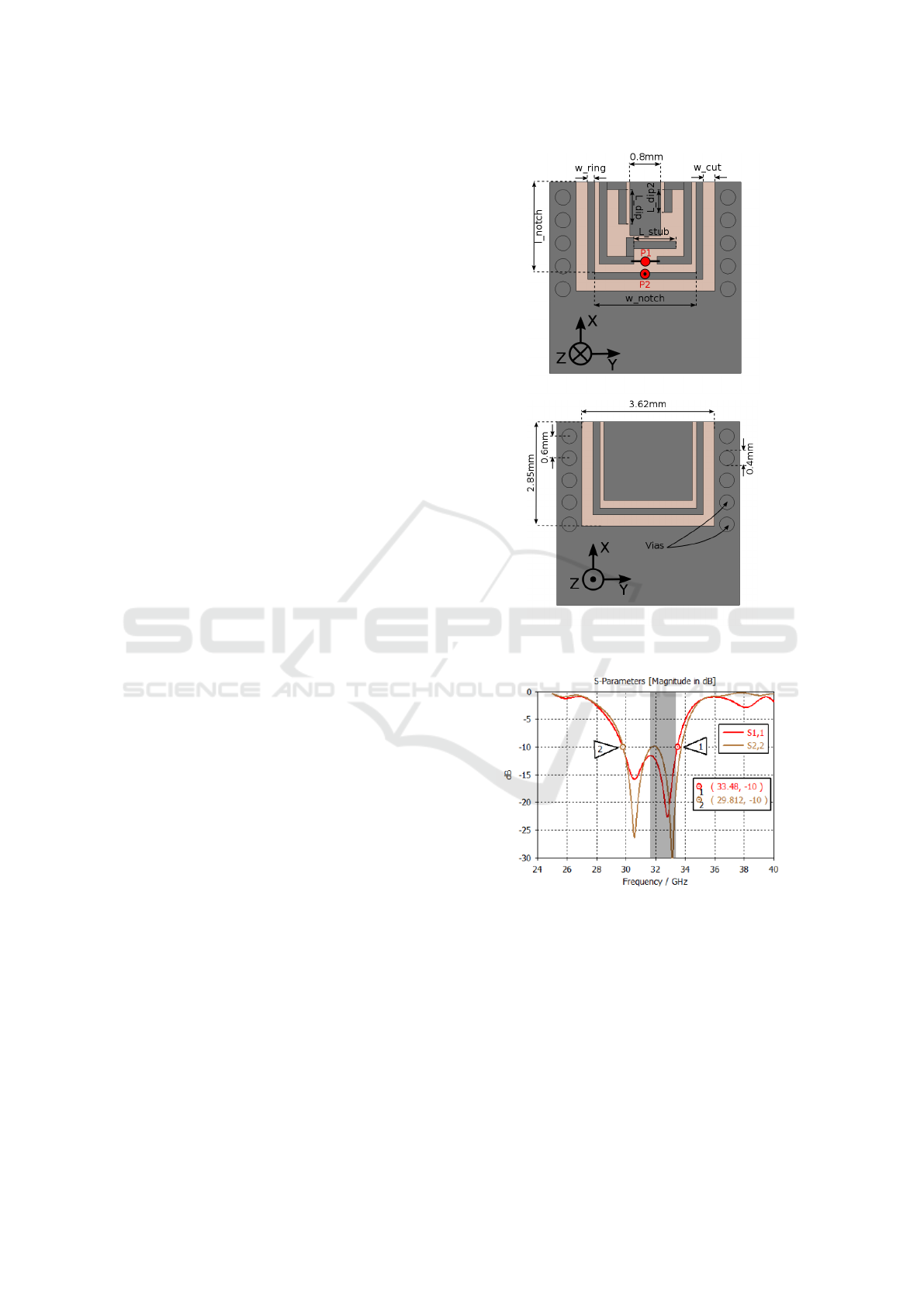
The geometry of the proposed antenna element is
shown in Figure 1. The antenna is built on the
Rogeres RO4350B substrate with a thickness of
0.762 mm. As shown in Figure 1, the dual polarized
antenna element consists of two parts. In simulation
setup, the dipole part is fed by the port P1, which is lo-
cated between the two dipole arms. The other port is
located between the top and bottom layer of the PCB.
The port 2 (P2) induces the currents on the top and
bottom rings around the patch in the middle, and thus
produce the radiation. In Figure 1 the constant geom-
etry dimensions are shown as numbers, and variable
dimensions are displayed in words. The variable di-
mensions can be altered in order to change the reso-
nant frequency of the antenna modes.
2.2 Antenna Operation Principle
The reflection coefficients at the ports 1 and 2 are
shown in Figure 2 and denoted as s-parameters S11
and S22. It can be noticed that two resonances ap-
pear when the antenna structure is fed at either port 1
or port 2. A resonance frequency of the first mode is
around 30.5 GHz and around 32.8 GHz for the second
mode. Furthermore, in Figure 2 a band from 31.8 to
33.5 GHz is visualized in a gray color.
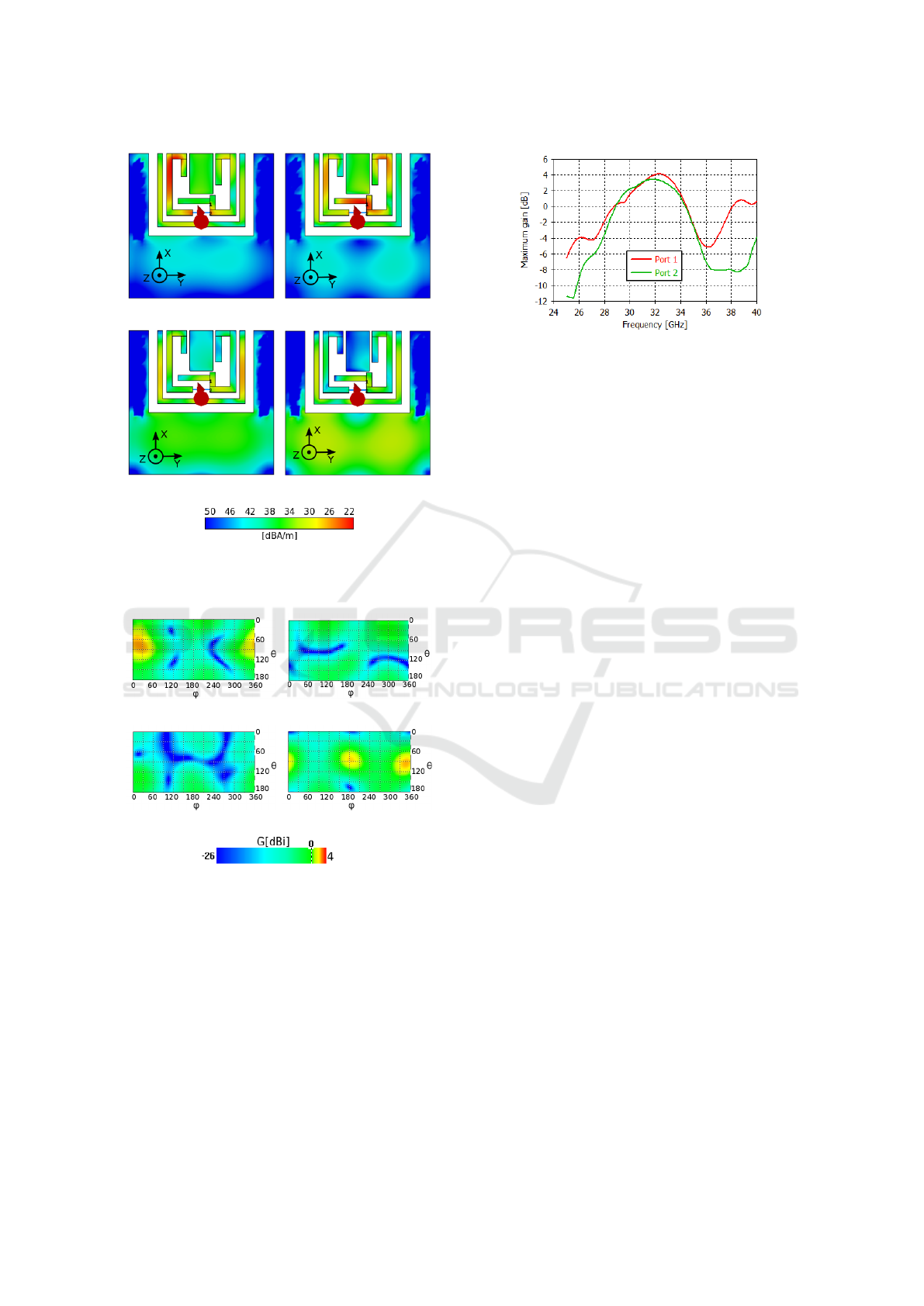
To grasp the operation principle of the proposed
antenna it has been chosen to show the maximum sur-
face currents on the antenna structure in Figure 3. The
substrate and the bottom layer are hidden. Notice the
orientation of Z-axes in the figure, which is pointing
outside of the paper. From both figures it is clear that
(a)
(b)
Figure 1: Geometry of the proposed antenna element (a)
front view, (b) back view.
Figure 2: Reflection coefficients at the port 1 and port 2.
the vias can efficiently reduce the surface wave on
the ground plane. The dipole is excited by the port
1 in Figure 3(a) at 30.5 GHz and in Figure 3(a) at
32.8 GHz. It can clearly be seen that in mode 1 the
radiation is created by the left dipole arm, and mode 2
is created by the currents running on the right dipole
arm and stub. In comparison to the dipole modes,
the modes of the rings induce higher currents on the
ground plane in Figure 3(c) and Figure 3(d). When
port 2 is excited at 30.5 GHz then the highest cur-
rents are concentrated on the ring (left and right side).
WINSYS 2018 - International Conference on Wireless Networks and Mobile Systems
310
(a) (b)
(c) (d)
Figure 3: Maximum surface currents on the antenna struc-
ture produced by the (a) port 1 – mode 1, (b) port 1 – mode
2, (c) port 2 – mode 1, and (d) port 2 – mode 2.
(a) (b)
(c) (d)
Figure 4: Radiation pattern of the proposed antenna struc-
ture excited at (a) port 1 - yz-polarization, (b) port 1 - xz-
polarization, (c) port 2 - yz-polarization, and (d) port 2 -
xz-polarization.
However, when port 2 is excited at 32.8 GHz, then the
currents are equally distributed among the ring and
ground plane. Furthermore, the patch in the middle,
between dipole arms, is added to tune the impedance
matching of a dipole. Thus, the patch is not excited
when the ring is radiating instead of the dipole.
Figure 5: Realized gain over the frequency range of the pro-
posed antenna.
2.3 Antenna Performance
Next, it has been chosen to show radiation patterns
of the antenna structure excited with port 1 and port
2. Here, two distinct polarizations are defined: xz-
polarization and yz-polarization. The radiation pat-
tern of the proposed antenna structure is shown in
Figure 4. It can clearly be seen that the dipole antenna
structure has yz-polarization, as shown in Figure 4(a).
When the structure is excited by the port 1 the xz com-
ponent of the antenna gain is very low in Figure 4(b).
However, for when the structure is excited by the port
2 the xz component of the antenna gain has a highest
value in Figure 4(d).
Next, the maximum gain over the frequency range
from 24 to 40 GHz is shown in Figure 5. The realized
gain in the band of interest is higher than 2 dBi when
the antenna structure is excited by either port 1 or 2.
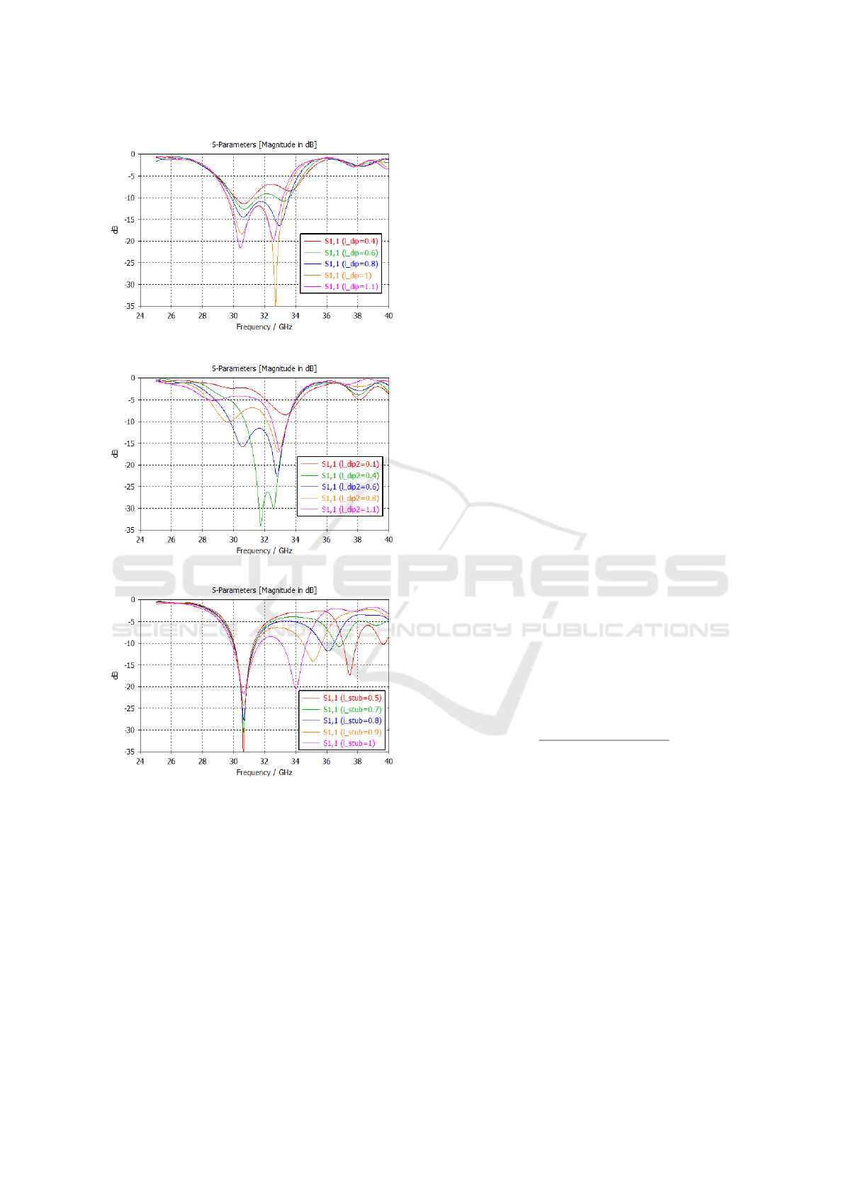
2.4 Dipole Design
In this section, it will be shown how to control the
resonance behavior of the dipole part of the proposed
antenna structure (when the structure is excited by the
port 1). The parametric results for the reflection co-
efficient at port1 are shown in Figure 6 for the three
different antenna structure parameters defined in Fig-
ure 1. First, the length of one of the dipole arms l
dip
is
changed from 0.4 to 1.1 mm as shown in Figure 6(a).
It can be seen that by changing that parameter the
matching of both modes is changing, but the reso-
nance frequency of modes remains the same. Next, in
Figure 6(b) the length of another dipole arm is swept
from 0.1 to 1.1 mm. Here more severe effect on the
resonance 1 is observed, but resonance frequency of
mode 2 remains the same. Finally, the length of the
stub is swept from 0.5 to 1 mm. Now the resonance
frequency of mode 2 changes significantly, while the
resonance frequency of the mode 1 is unchanged. To
move the antenna resonances one should first change
the resonance of mode 1 by changing the length l
dip2
Dual-polarized Dual-band Mobile 5G Antenna Array
311
(a)
(b)
(c)
Figure 6: Parametric results of the reflection coefficient
when lengths (a) l
dip
, (b) l
dip2
, and (c) l
stub
are permuted.
, then change the resonance of mode 2 by tuning the
length of stub l
stub
, and finally match the antenna ac-
cording to the specifications by tuning the parameter
l
dip
.
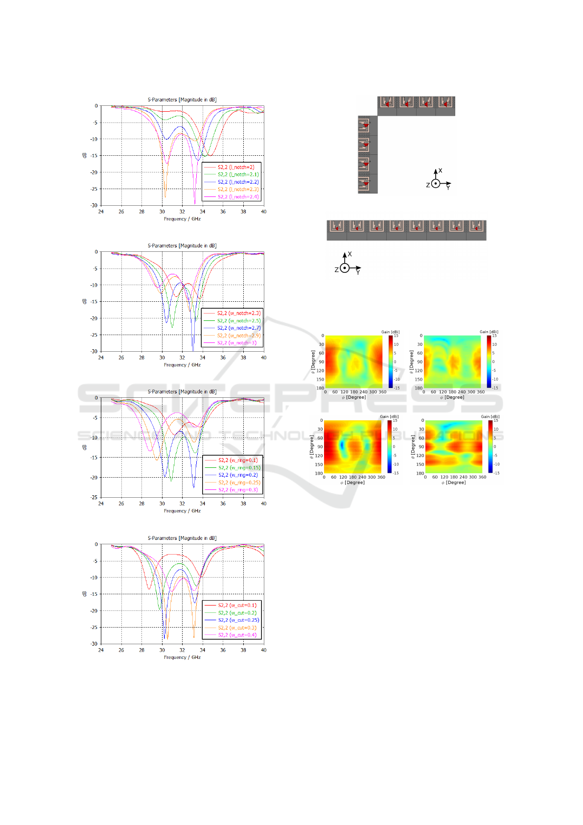
2.5 Notch Design
In this subsection it will be shown how to control
the resonance behavior of the notch part of the an-
tenna structure (when the antenna structure is excited
by the port 2). The corresponding antenna structure
parameters are defined in Figure 1. To tune the res-
onance frequencies of notch modes it has been cho-
sen to show the effect of changing the values of four
parameters of the antenna structure which is shown
in Figure 7. First, it can be noticed that a single pa-
rameter cannot be used to change the matching of the
antenna. The resonance frequency of the modes al-
ways shifts, so multiple notch parameters need to be
adjusted in order to change the matching of the an-
tenna. To change the resonance frequency of mode
2 the parameter l
notch
and w
notch
should be permuted
in Figure 7(a) and Figure 7(b). However, if the reso-
nance frequency of mode 1 is to be altered, then the
parameters w
ring
, w
cut
, and w
notch
should be permuted.
It can be already noticed that the design of the notch
part of the antenna is more complicated and not so
straightforward as the dipole design.
3 PERFORMANCE OF THE
PHASE ARRAY
In this section, the performance of the mm-wave
phased array constructed by using the proposed dual-
polarized antenna element will be investigated. To in-
vestigate the performance of the array the metrics of
the total scan pattern and coverage efficiency are used.
The coverage efficiency is calculated from the total
scan pattern (TSP) of the phased array or switchable
antenna array system and obtained from all antenna
array patterns, corresponding to the different scan an-
gles. The best achievable gain is extracted at every
spatial point.
The coverage efficiency is defined as (Helander
et al. (2016)):
η
c
=
Coverage Solid Angle
Maximum Solid Angle
(1)
where the maximum solid angle defined as 4π stera-
dians. The coverage efficiency has no unit and varies
from 0 to 1 (corresponding to 0 and 100 % coverage).
3.1 Array Geometry
In this paper, it has been chosen to investigate the
performance of the proposed antenna element in the
linear arrays in two configurations. The two array
configurations are shown in Figure 8. In the con-
figuration 1 in Figure 8(a) 8 elements are distributed
into two sub-arrays of four elements, perpendicular to
each other. And in the configuration 2 in Figure 8(b)
8 same elements are combined into one linear array of
8 elements. The point is to investigate which configu-
ration has better performance. From the system point
WINSYS 2018 - International Conference on Wireless Networks and Mobile Systems
312
(a)
(b)
(c)
(d)
Figure 7: Parametric results of the reflection coefficient
when lengths (a) l
notch
, (b) w
notch
, (c) w
ring
, and (d) w
cut
are permuted.
(a)
(b)
Figure 8: Two configurations of the phased antenna array
(a) two sub-arrays of four elements and (b) one 8-element
phased array.
(a) (b)
(c) (d)
Figure 9: Total scan patterns of (a) configuration 1 – xz
polarization, (b) configuration 1 – yz polarization, (c) con-
figuration 2 – xz polarization, and (d) configuration 2 – yz
polarization.
of view, the configuration 1 requires less complicated
feeding network and SPDT switch. Where the config-
uration 2 requires more complicated feeding network
but no switch. Furthermore, the sub-arrays in the con-
figuration 1 is oriented perpendicular to each other in
order to maximize the coverage (scanning in xz and
yz-planes). On the other hand, the phased array in the
configuration 2 can only scan in yz-plane.
The total scan patterns of the two proposed phased
antenna array configurations at 32 GHz are shown in
Fig. 9. It can be seen that the maximum gain in the
configuration 1 in lower than the maximum gain in
the configuration 2. However, side lobes are higher in
the case of configuration 2 in Figure 9(d).
Dual-polarized Dual-band Mobile 5G Antenna Array
313
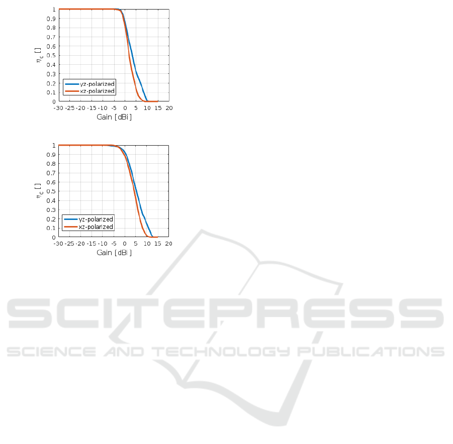
(a)
(b)
Figure 10: Coverage efficiency of phased antenna array in
(a) configuration 1 and (b) configuration 2.
Finally, the coverage efficiency of the array in two
configurations is calculated and shown in Figure 10.
First, it can be noticed that difference in the coverage
between two polarization is very small for the gains
lower than 0 dBi. However, a bigger difference can
be seen as the gain increases. Finally, the curves for
the array configuration 1 and configuration 2 have a
very similar slope, but the absolute level of the cov-
erage is different. It can be seen that the array in the
configuration 1 have 20 % less coverage for the gain
of 5 dBi.
4 CONCLUSION
In this paper, a dual-polarized dual-band phased an-
tenna array for 5G mobile devices has been presented.
The proposed array have the bandwidth of 3.6 GHz
and covers the band of 30.8 to 33.4 GHz. Further-
more, it has been shown how to tune each mode of the
antenna in order to achieve the desired bandwidth and
resonance frequency of each mode. Next, two phased
array configurations have been investigated. One con-
figuration has 8 array elements distributed into two
4-element sub-arrays oriented orthogonally with re-
spect to each other. It has been found that array of
8 elements give better spatial coverage performance.
However, this investigation has only been done for the
broadside antenna element. A further investigation of
endfire antenna element should also be conducted in
the future work.
REFERENCES
Helander, J., Zhao, K., Ying, Z. & Sjöberg, D. (2016), ‘Per-
formance analysis of millimeter-wave phased array
antennas in cellular handsets’, IEEE Antenna Wireless
Propagation Letters 15, 504–507.
Hong, W., Baek, K., Lee, Y. & Kim, Y. G. (2014), ‘Design
and analysis of a low-profile 28 GHz beam steering
antenna solution for Future 5G cellular applications’,
Microwave Symposium (IMS), 2014 IEEE MTT-S In-
ternational pp. 1–4.
Hong, W., Ko, S. T., Lee, Y. & Baek, K. H. (2015), ‘Multi-
polarized antenna array configuration for mmWave
5G mobile terminals’, 2015 International Workshop
on Antenna Technology (iWAT) pp. 60–61.
Hussain, R., Alreshaid, A. T., Podilchak, S. K. & Sharawi,
M. S. (2017), ‘Compact 4G MIMO antenna inte-
grated with a 5G array for current and future mobile
handsets’, IET Microwaves, Antennas & Propagation
11(2), 271–279.
Lee, J., Tejedor, E., Ranta-aho, K., Wang, H., Lee, K. T.,
Semaan, E., Mohyeldin, E., Song, J., Bergljung, C. &
Jung, S. (2018), ‘Spectrum for 5g: Global status, chal-
lenges, and enabling technologies’, IEEE Communi-
cation Magazine 56(3), 12–18.
Mahmoud, K. R. & Montaser, A. M. (2018), ‘Design of
dual-band circularly polarised array antenna pack-
age for 5G mobile terminals with beam-steering ca-
pabilities’, IET Microwaves, Antennas Propagation
12(1), 29–39.
Nielsen, J. O. & Pedersen, G. F. (2016), Dual-polarized in-
door propagation at 26 ghz, in ‘2016 IEEE 27th An-
nual International Symposium on Personal, Indoor,
and Mobile Radio Communications (PIMRC)’, pp. 1–
6.
Ojaroudiparchin, N., Shen, M. & Pedersen, G. F. (2015),
‘Design of Vivaldi antenna array with end-fire beam
steering function for 5G mobile terminals’, 2015
23rd Telecommunications Forum Telfor (TELFOR)
pp. 587–590.
Ojaroudiparchin, N., Shen, M., Zhang, S. & Pedersen, G. F.
(2016), ‘A Switchable 3-D-Coverage-Phased Array
Antenna Package for 5G Mobile Terminals’, IEEE
Antennas Wireless Propagation Letters 15, 1747–
1750.
Rappaport, T. S., Sun, S., Mayzus, R., Zhao, H., Azar, Y.,
Wang, K., Wong, G. N., Schulz, J. K., Samimi, M. &
Gutierrez, F. (2013), ‘Millimeter wave mobile com-
munications for 5G cellular: It will work!’, IEEE Ac-
cess 1, 335–349.
Rehman, M. U., Chen, X., Parini, C. G. & Ying, Z. (2012),
‘Evaluation of a statistical model for the characteriza-
tion of multipath affecting mobile terminal GPS an-
tennas in sub-urban areas’, IEEE Transactions on An-
tennas and Propagation 60(2), 1084–1094.
WINSYS 2018 - International Conference on Wireless Networks and Mobile Systems
314

Roh, W., Seol, J. Y., Park, J., Lee, B., Lee, J., Kim, Y.,
Cho, J., Cheun, K. & Aryanfar, F. (2014), ‘Millimeter-
wave beamforming as an enabling technology for 5G
cellular communications: theoretical feasibility and
prototype results’, IEEE Communication Magazine
52(2), 106–113.
Shuai Zhang, Igor Syrytsin, G. F. P. (2018), Substrate-
insensitive phased array with improved circularly-
polarized scan angle for 5G mobile terminals, in ‘Eu-
CAP 2018, the 12th European Conference on Anten-
nas and Propagation’.
Syrytsin, I., Zhang, S. & Pedersen, G. F. (2017), Circu-
larly polarized planar helix phased antenna array for
5g mobile terminals, in ‘2017 International Confer-
ence on Electromagnetics in Advanced Applications
(ICEAA)’, pp. 1105–1108.
Syrytsin, I., Zhang, S., Pedersen, G. F. & Morris, A. (2018),
‘Compact quad-mode planar phased array with wide-
band for 5g mobile terminals’, IEEE Transactions on
Antennas and Propagation (In press) .
Zhang, S., Chen, X., Syrytsin, I. & Pedersen, G. F. (2017),
‘A Planar Switchable 3D-Coverage Phased Array An-
tenna and Its User Effects for 28 GHz Mobile Ter-
minal Applications’, IEEE Transactions on Antennas
and Propagation 65(12), 6413–6421.
Dual-polarized Dual-band Mobile 5G Antenna Array
315
