
Aided OWL Notation (AOWLN): Conceptual Modelling and
Visualisation of Advanced SWRL Rules
Johannes Nguyen, Jannik Geyer, Thomas Farrenkopf and Michael Guckert
KITE - Technische Hochschule Mittelhessen, Wilhelm-Leuschner-Straße 13 , Friedberg, Germany
Keywords:
Graphical Rule Representation, SWRL, OWL, Rule Visualisation.
Abstract:
Ontologies are a common and generally accepted instrument for the documentation of knowledge in a forma-
lised machine readable form. This paper focuses on ontologies encoded in Web Ontology Language (OWL).
OWL is description-logic based and can be extended by using Semantic Web Rule Language (SWRL) to express
Horn clause like rules that allow the ontology to go beyond the scope of the more object-centric description
logic propositions. The combination of OWL and SWRL has proved to be highly useful in practical appli-
cations. However, SWR L rules soon become complex and confusing in mere textual representations. This
particular issue becomes obvious w hen ontologies grow in size and the number of rules increases. A solution
for this problem can be an appropriate graphical representation of the rules. This paper proposes a graphical
visualisation concept for SWRL rules that we call Aided OWL Notation (AOWLN). Additionally, we present a
prototypical Prot´eg´e plugin that automatically visualises rules.
1 INTRODUCTION
Gruber described ontologies to be an explicit speci-
fication of a conceptualisa tion which was later re-
formu late d by Borst to also be shared (see (Guarino
et al., 2009) for a discussion). Ontologies define con-
cepts together with their properties a nd interrelations
in a formal and machine readable form. They have
become a common instrument for consistently docu-
menting knowledge to be sha red among humans and
machines. Having the idea of supporting interopera-
bility as a major purpose, standardisation is an im-
portant issue. W3C has standardised OWL. Being an
object-centric language OWL has limitations in ex-
press rather simple if-then constructions, e.g. for as-
serting data or object prope rties. Therefore, the com-
bination of OWL together with Semantic Web Ru le
Language (SWRL) is a frequ e ntly used set of tools.
1.1 Motivation
SWRL extend s OWL with the ability to use Horn
clause like if-then rules. SWRL is a proposed W3C
standard that has gained pop ularity in re c ent years.
With a growing developer base, the lack of options to
visualise rules becom e s more and more relevant. In
February 2017 Martin O’Connor (cre a tor of Prot´eg´e)
and other developers addressed this topic in a web fo-
rum, resulting in an open call for an appropriate vi-
sualisation tool.
1
Although this is not a new de bate,
most existing solutions have limitations, making the
development o f an easy to u se visualisation too l for
SWRL a necessity.
1.2 Problem
Rules expressed with SWRL incr ease the visual com-
plexity o f an ontology. With complex mathematical
formu las invoking SWRL built-ins, rules can easily
stretch over several lines which makes reading and
comprehending difficult. However, in pra ctical indus-
trial applicatio ns highly complicated rules cannot be
avoided as expressing engineering problems requires
mathematical formulas that lead to extensive use of
built-ins inducing high complexity. Th is makes it dif-
ficult if not impossible to follow the logical structure
of the rules, even for domain experts. So far, Prot´eg´e
only o ffers limited op tions to search and ide ntify spe-
cific rules. A n integrated graphical visualisation w ill
lead to higher transparency and a b etter overview, ma-
king the rules more comprehensible. A new graphical
notation format for SWRL rules with higher transpa-
rency need s to be defined.
1
See http://protege-project.136.n4.nabble.com/
Visualisation-tool-for-OWL-and-SWRL-rules-
td4667578.html - (accessed on 06/01/2018)
Nguyen, J., Geyer, J., Farrenkopf, T. and Guckert, M.
Aided OWL Notation (AOWLN): Conceptual Modelling and Visualisation of Advanced SWRL Rules.
DOI: 10.5220/0006917701750182
In Proceedings of the 10th International Joint Conference on Knowledge Discovery, Knowledge Engineering and Knowledge Management (IC3K 2018) - Volume 2: KEOD, pages 175-182
ISBN: 978-989-758-330-8
Copyright © 2018 by SCITEPRESS – Science and Technology Publications, Lda. All rights reserved
175

1.3 Idea
The contribution of this work is a proposal for a
set of notation elements that a re able to portray the
main logical constructs used in SWRL. We will spe-
cify an algor ithm that composes the newly defined
notation elements into a diagram. In our initial a p-
proach e s we attempted to model SWRL rules using
UML and BPMN notation elements. However, the
elements available there are semantically inapprop ri-
ate an d can lead to BPMN and UML diagrams con-
tradicting the SWRL logic. Furtherm ore, we pr esent
prototy pical visualisation tool that can be implemen-
ted as a Pr ot´eg´e plugin.
1.4 Outline of the Paper
The following section provides a technology review,
giving an overview of the most important existing so-
lutions for visualising SWRL rules, inter alia, Prot
´
eg
´
e
Axiom
´
e which is a known visualisation plugin for
Prot´eg´e. Section 3 introduces a new set of notation
elements for the graphical visualisation and in section
4 an example is p resented as proof of concept. This
example demonstrates the transformation of r ule gi-
ven in textual description into our graphical notation.
Finally, the implementation of the visualisation plugin
is described.
2 RELATED WORK
In this section, other approaches to visualise ru le s in
ontologies are discussed.
2.1 Prot
´
eg
´
e Axiom
´
e
Prot´eg´e Axiom´e was developed by the creators of
Prot´eg´e. It is a plugin that consists of five main func ti-
onal areas (Hassanpour et al., 2009). Th e first functi-
onal area is a rule gr a ph for visualising th e interde-
pendencies between individual rules to repr esent an
entire rule base. The rules are portrayed as nodes
that are connected through directed edges. Besides
this, the tool also offers an option for rule para phra-
sing. This option enables the creation of English like
text representations for individual rules and catego-
rises them based on their syntactic structure. Addi-
tionally, a rule elicitation function was implemente d
that creates templates for adding new rules to th e ru le
base. Prot´eg´e Axiom´e visualisation uses a tree struc-
ture cre a te d by applying Depth First Search to chain
the variables (Hassanpour et al., 2009). By cha ining
variables a simple flowchart diagram which visualises
the basic logical sequence for data and ob je ct proper-
ties is derived. However, the tool neither differentiates
between existing SWRL e lements nor does it clarify
the application of built-ins (see Fig. 1). A more ap-
propriate modellin g concept for visualisation should
include more information about the rule and its con-
stituents. Furthermore, the tool at this stage is not up-
to-date as it has not been ported to the current version
of Prot´eg´e 5.0.
³F´KDV2ZQHU´S´
³S´KDV'ULYHU/LFHQVH³G´ ³S´FDQ'ULYH³F´
)LJXUH
Figure 1: Axiom´e – individual rule visualisation.
2.2 Poznan University of Technology
Graph-based Editor
In 2013, Jaroslaw Bak and his team fro m Poznan Uni-
versity of Technology published a prototypical imple-
mentation of a graphed-based editor for SWRL rules.
The edito r focuses on the visu alisation of individual
SWRL rules. It is based on a set of new modelling
elements for the illustration of rules in diagrams (see
Fig. 2).
&ODVV &ODVV,QVWDQFH 2EMHFW'DWD3URSHUW\ 9DOXH
)LJXUH
Figure 2: Set of notation elements.
This approach distinguishe s separate taxonomies for
Classes, Data Properties, and Object Properties (Bak
et al., 2013). The ed itor creates a diagram for each of
the three taxonomies, allowing the user to choose be-
tween different pe rspectives. The diagrams are split
into two sections (see Fig. 3) (Bak et al., 2013). The
left-hand section portra ys th e condition elements (a n-
tecedent) of an SWRL rule whereas the right-hand
section shows the conclusion (consequent).
FDQ'ULYH
"S "F
KDV'ULYHU/LFHQVH KDV2ZQHU
3HUVRQ"S
'ULYHU/LFHQVH"G &DU"F
&RQGLWLRQV &RQFOXVLRQ
)LJXUH
Figure 3: Poznan Graph Editor - SWRL visualisation.
In general, this mo delling approach offers a lot of po-
tential as it is visually self-explaining, but it is limi-
ted when tryin g to show the impact of built-ins or
KEOD 2018 - 10th International Conference on Knowledge Engineering and Ontology Development
176
restrictions. However, built-ins are essential compo-
nents of SWRL necessary to implem ent mathematical
operations. The sepa ration of the representation into
different views can be considered a deficiency. A uni-
fied diagram for all three perspectives may improve
general understanding of the rule. Despite this, we
agree that the visual separation of rule antecedent and
consequent is as a good approach.
2.3 Graph Inscribed Logic (Grailog)
Grailog is a combination of g eneralised graph con-
structs fo r visualising data, inter alia, Horn logic
(Boley, 2013). The visualisation is adapted to the
industry standard RuleML. With Grailog a new
concept of hypergraphs is introduce d which is a
proposed enhancement in compar iso n to directed
labelled graphs (Boley, 2013). According to Boley,
directed labelled graphs (DLG) are a good starting
point for visual knowledge representation but come
with major disadvantages when trying to illustrate
non-binary relationships (Boley, 201 3). This is why
he created hyperarcs as specialised arrows for h is
notation. The following graphs show a c omparison
of a hypergraph on the left-hand side and a directed
labelled graph on the right-hand side (see Fig. 4).
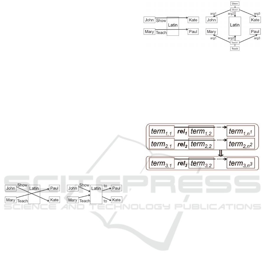
Figure 4: Hypergraphs in comparison to DLG 1 (Boley,
2013).
Both diagrams in Fig . 4 show the two statements:
”John shows Latin to Kate”
”Mary teaches Latin to Paul”
Using a directed labelled gr a ph has the disadvantage
of losing th e context of input and output arrows
(Boley, 2013). This means that the graph may also
be misin te rpreted as “John shows Latin to Paul”
and “Mary teaches Latin to Kate”. However, the
hypera rcs provide a means to unmistakably define
the non -binary relationship. When trying to correctly
and unambiguously illustrate the two given sentences
as a DLG, the graph becom es significantly more
complex, demonstrating a major advantage of Grailog
Hypergraphs (see Fig. 5).
Grailog also offers the possibility to formulate advan-
ced logic using the idea of so called c omplex nodes.
According to Grailog, a graph can co nsist of elemen-
tary nodes such as John and Kate. Moreover, a com-
plex node is able to contain othe r grap hs, making it an
Figure 5: Hypergraphs in comparison to DLG 2 (Boley,
2013).
enclosing entity. Based on this, it is also possible to
express Horn Logic using a combination of complex
nodes in Grailog ( see Fig. 6) (Bo ley, 2013). Although
Grailog can describe Horn Logic, it is not specialised
for SWRL m aking it difficult to portray SWRL built-
ins. In this paper, we f ocus on a more specia lised
solution for SWRL ru le s.
Figure 6: Grailog - Horn logic (Boley, 2013).
2.4 Using UML State Diagrams for
Visualising Business Rules
In 2008, Konrad Kułakowski and Grzegorz J. Na-
lepa pu blished a modelling approach for business ru-
les using UML diagrams. The main idea is to repre-
sent a rule base as a class diagra m. Based on this,
each class repre sents a single rule. Th e class diagram
then shows dependenc ies between different rules (Ku-
lakowski and Nalepa, 200 8). Furtherm ore, each class
has its own state diagram which is describe d as a rule
definition d iagram. The paper defines rules a s plain
textual if-then statements (Kulakowski and N alepa,
2008). The rule d efinition diagram expresses condi-
tions using the UML standard Object Co nstraint Lan-
guage (OCL). As the proposed modelling format is
designed for business rules in g eneral, the possibili-
ties to visualise m ore complex SWRL logic rules are
limited.
3 CONCEPTUAL MODELLING
Before we define our notation elements we give a
brief discussion of relevant aspects of ontologies and
rules.
Aided OWL Notation (AOWLN): Conceptual Modelling and Visualisation of Advanced SWRL Rules
177
3.1 OWL/SWRL Elements
OWL is a standardised general knowledge represen-
tation language for creating ontologies (McGuinness
et al., 20 04). The elements of OWL are often de no-
minated as a toms when used in rules.
An ontology O is a triple (C ,R ,I ). C is a set of c on-
cepts, R a set of relations, and I a set of individual
objects. Concepts (i.e. Classes) formally d e note sets
of objects. From a perspective of formal logic, these
sets are the extension of concepts while con c epts de-
fine the intentional r e presentation of the correspon-
ding set of objects. An obje ct that belongs to a con-
cept is called an instance of that concept. The ele-
ments of R are relations (also called roles or object
properties, as they manife st links on the level o f the
instances) having subsets of C as domain and range.
The extension of a role then is a set of pairs (c, d)
with c, d elements of I . Additionally, instances can
have data properties through which they get linked to
primitive data e.g. strings or numbers. Typically, on-
tologies are formulated by means of description lo-
gics with differing levels of expressiveness (Baader,
2003). Usually description logics are proper subsets
of first order logic where expressiveness has been tra-
ded for decidability. Inf erence knowledge is impli-
citly given by the underlying mechan ism s of the avai-
lable reasoning instruments. Apar t from this, SWRL
as an extension also includes elements for restricti-
ons and built-ins (McGuin ness et al., 2004). Built-ins
can be de scribed as operators similar to methods or
functions respectively in conventional pro gramming
languag es. For instance, mathematical operatio ns and
data type restrictions can be expressed through built-
ins. The following table summarises the mo st signifi-
cant elements and the corresponding syntactic struc-
ture when used in SWRL rule s.
Table 1: OWL/SWRL E lements.
OWL/SWRL Element Syntax
Class Person
Individual /
Class instance
Person(bob) /
Person(alice)
Data Property canDrive(bob, true)
Object Property isSon(bob, alice)
Built-ins swrlb:lessThan(?age,18)
Restrictions integer[> 0]
Variable ?age
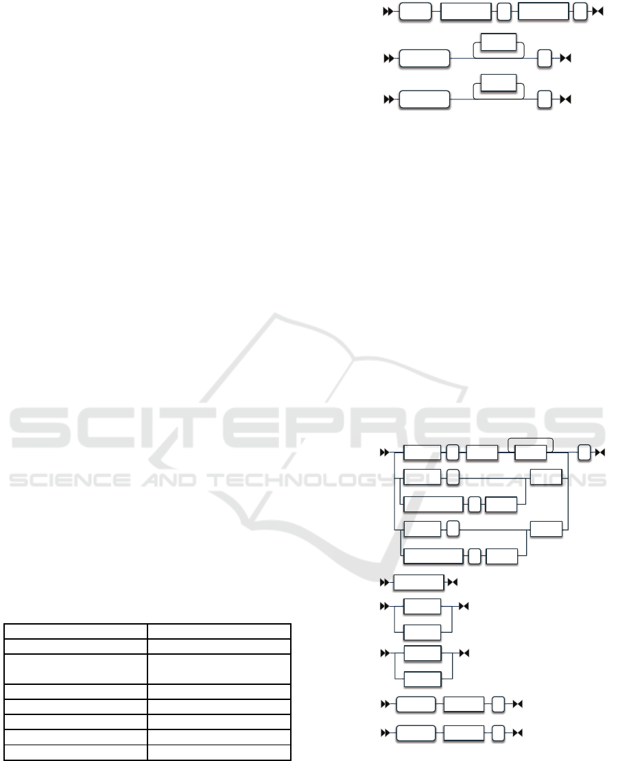
3.2 SWRL Syntax Diagram
Horrocks (2004) d e fines a SWRL rule as a pair (A,
C) in which both, antece dent A and conseq uent C are
sets of atoms S
A
and S
C
(see Fig. 7).
Implies( )
antecedent consequent
Antecedent(
atom
)
Consequent(
atom
)
SWRL Rule
Antecedent
Consequent
Figure 7: SWRL syntax diagram 1.
An atom element r
A
must be de c la red w ith an atom
name ∈ B
N
∪C
N
∪ O
P
∪ D
P
∪ D
R
for which B
N
is th e
set of built-in names, C
N
the set of c lass names, O
P
the set of object property names, D
P
the set of data
pro perty names and finally D
R
the set o f data ranges.
A built-in name b
N
is followed by zero or one built-
inID and at least one or more d-objects. The built-in
ID is a variable in which the built-in output is written.
A d- object can be a data literal o r a d-va riable which
in the second case is an URI reference to an entity de-
fined in the ontology. A class name C
N
is followed
by an i-object which can either be an individual-ID or
an i-variable. An i-variable is an URI reference to an
entity defined in the ontology. Apart fr om this, an ob-
ject property name o
P
is followed by a pair (i-object,
i-object) and a data property name d
P
compleme nted
by a pair (i-obje c t, d-object). A data range d
R
is fol-
lowed by a single d-object (see Fig. 8).
Atom
builtInName ( builtInID
d-object
)
className
(
i-object
objectPropertyName
(
i-object
dataRange
(
d-object
dataPropertyName
(
i-object
URIreference
BuiltInID
i-variable
Individual-ID
i-object
d-variable
dataLiteral
d-object
URIreferenceI-variable(
)
URIreferenceD-variable(
)
d-variable
i-variable
Figure 8: SWRL syntax diagram 2.
3.3 AOWLN Graph Structure
As discussed before, directed labelled graphs are we ll
suited to visualise logical sequences (see Section 2).
In order to visualise SWRL rules, a corresponding
KEOD 2018 - 10th International Conference on Knowledge Engineering and Ontology Development
178

graphica l symbol for each of the existing semantic
OWL/SWRL elements has been mapped a nd c an be
composed into a graph.
For a given SWRL rule R
A
we define a Graph G and
map the components of R
A
to nodes of G. Th e graph
consists of a heterogeneous set o f vertices V = R ∪
O ∪ T ∪ D (R be ing a set of rectangles (class nodes),
O a set of ovals (property nodes), T a set of trapeziums
(variable nodes) and D a set of d iamond shapes (built-
in collection nodes) an d edges E = D
E
∪ O
E
∪ B
E
)
(D
E
being a set of unlabelled solid arrows ( data pro-
perty edges), O
E
a set of dashed unlabelled arrows
(object property edg es) and B
E
a set of solid and la-
belled arrows (built-in edges). T he mapp ing is des-
cribed in figure 9.
&ODVVHV
'DWD3URSHUW\
2EMHFW3URSHUW\
9DULDEOH
%XLOWLQ&ROOHFWLRQ
%XLOW,Q
5
9
(
5
$
2
%XLOWLQ1DPH
'
*
2EMHFW3URSHUW\
7
'
(
2
(
%
(
Figure 9: AOWLN elements.
According to this mapping, classes are represented
by rectangle shapes and properties by oval shapes.
Properties associated with classes are connected to
the corresponding class e le ment with an edge. E dges
are unlabelled and directed. Wh ile class nodes a nd
data properties as well as variables are connected
with solid lines, ed ges associated with object p ro-
perties are dashe d. Variables are re presented by
trapezium shapes. In SWRL data type restrictions
and operations can be expressed with built-ins.
Data type re strictions are written into the lower half
of a property symbol, sepa rated by a dashed line.
Moreover, built-ins are visualised by labelling the
edge that progresses towards the resulting variable.
If multiple built-ins result in the same variable, these
built-ins are summarised into a new diamond shaped
Built-in Collection element.
For both rule antecedent and consequent separate
graphs a re created which are displayed in juxtaposi-
tion. The following pseudocode sketches th e creation
of the graph.
List aowlnElements
List aowlnEdges
function createAOWLNGraph(RuleFragment rf)
for each classAtom in rf
if classAtom not in aowlnElements
aowlnElements add classAtom
completeLogicalSequence(classAtom, rf)
for each ObjectPropAtom in rf
if classAtom is firstArg:
appendAtom (classAtom, ObjectPropAtom)
classAtom = ObjectPropAtom.SecondArg
completeLogicalSequence(classAtom, rf)
endIf
endIf
endFor
aowlnGraph = new Graph(aowlnElements, aowlnEdges)
function appendAtom (startAtom, nextAtom)
aowlnElements add nextAtom
aowlnEdges add new Edge(startAtom, nextAtom)
function completeLogicalSequence(classAtom, ruleFragment)
for each DataPropAtom in ruleFragment
if classAtom is firstArg:
appendAtom (classAtom, DataPropAtom)
currentAtom = DataPropAtom
while (successorAtom not null) do
successorAtom =
findLogicalSuccessor(successorAtom, ruleFragment)
appendAtom(currentAtom, successorAtom)
currentAtom = successorAtom
endWhile
varElement = currentAtom.getResultingVar()
appendAtom(currentAtom, varElement)
endIf
endFor
By convention, for e a ch variable instance of a
class, a class node is crea te d explicitly. Furthermore,
the last variable of a logical sequence must be
indicated. A logical sequence is the concatenation of
SWRL atoms through joint references to variables.
However, variables th a t are passed on to consequen-
tial properties or built-ins ma y be skipped in the
visualisation to avoid redundant graph elem e nts. For
logical sequences that end with a class a tom no de
(i.e. objec t properties) the variable node at the end
of the sequence can be omitted as class atoms are
explicitly created for each variable instance of a class.
The algorithm de scribed above requir es a sequ ential
ordering of the atoms in the SWRL rule:
1. Class 1
a. class1DataProperty1
b. class1TransitiveNextProperty1
i. c1TNP1BuiltIn1
ii. c1TNP1BuiltIn 2
iii. c1TNP1Restriction
c. class1TNP2
Aided OWL Notation (AOWLN): Conceptual Modelling and Visualisation of Advanced SWRL Rules
179
d. class1TNPN
2. Class2
3. ...
4. ClassN
(1) objectProperty 1
(2) objectProperty 2
(3) ...
(4) objectProperty N
⇒ Conclusion
The rule conclusion is processed just like that. The
ordering en sures the affiliation of transitive e le ments
simplifying the implementation. Built-ins which only
use a single variable in position one will not be visu-
alised. See the following example:
1. add(?ageNew, ?age, 10)
2. add(?ageNew, 6, 10)
The SWRL math built-in, swrlb:add() is used. This
built-in is satisfied if the first argument is equal to the
arithmetic sum of the f ollowing arguments (Horrocks
et al., 2004). Henc e, the built-in writes the result into
the first variable ?newAge. In the first case, the varia-
ble ?newAge is derived from the variable ?age. In th e
second case the ope rands of the summation are con-
stants a nd will no t be visualised because they are not
part of a logical sequence. This en hances the reada-
bility of the graph by eliminating nodes of low mea-
ningfulness.
4 EXAMPLE OF APPLICATION
The following example demonstrates the use of the
notation elements.
Textual Description:
Individuals under the age of 18 as a potential driver of
a vehicle with a weight of less than 26,000 lbs are able
to drive in California if they possess an out-of-state
driver’s license except for New York and are visiting
the state for less than 10 days. For this, the person
must be the owner of the car.
Table 2: AOWLN Elements Mapping.
Concept / Class Data Property
→ Built-In
Object Property
Person(?p) hasAge(?p,?g)
→ lessThan(18)
ownsCar(?p,?c)
Car(?c) numberOfVisiting-
InDaysInCA(?p,?x)
→ lessThan(10)
hasDriverLicence(?p,?d)
DriverLicense(?d) issuedStateOf(?d,?s)
→ notEqual(s,”CA”)
→ notEqual(s,”NY”)
hasWeightInLBS(?x,?w)
3HUVRQS
KDV'ULYHU
/LFHQVH
LVVXHG6
WDWH2I
KDV$JH
QXPEHU2I9LVLWLQJ
'D\V,Q&$
&DUF
RZQV
&DU
KDV:HLJKW,Q/%6
&RQFOXVLRQ
3HUVRQS
FDQ
'ULYH
'ULYHU/LFHQVHG
%&
V
J
[
Z
&DUF
)LJXUH
SWRL:
Person(?p) ∧ hasAge(?p, ?g) ∧ swrlb : lessT han
(?g, 18) ∧ numberO fVisitngDaysInCA(?p, ?x) ∧
swrlb : lessT han(?x, 10) ∧ D riverLicense(?d) ∧
hasDriverLice nse(?p, ?d) ∧ issuedInStateO f (?d, ?s)
∧ swrlb : notEqual(?s,
′′
CA
′′
) ∧ swrlb : notEqual
(?s,
′′
NY
′′
) ∧ Car(?c) ∧ hasWeightInLB S(?c, ?w) ∧
swrlb : lessT han(?w, 26000) ∧ ownsCar(?p, ?c)
⇒ Person(?p) ∧Car(?c) ∧ canDrive(?p, ?c)
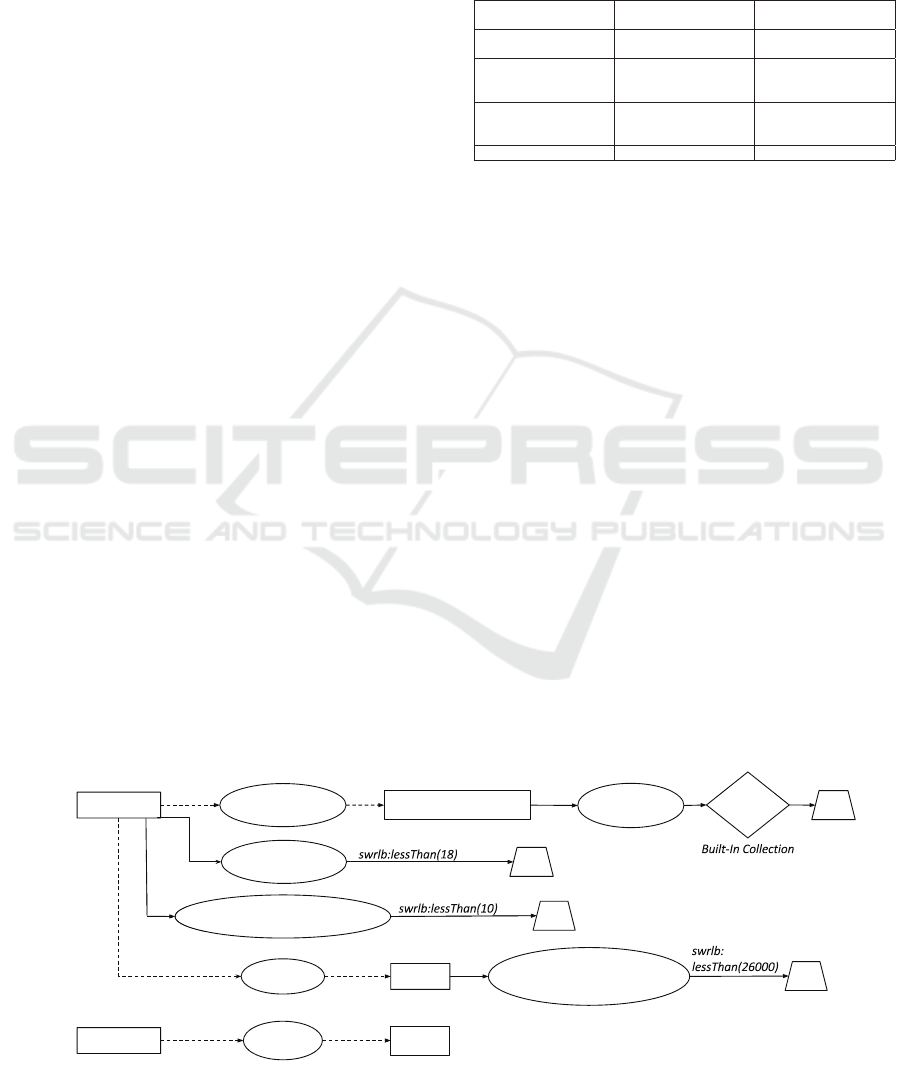
AOWLN:
As the Fig. 10 displays, there is a separatio n of rule
conditions and the rule conclusion similar to the Po-
znan graph editor (see Sectio n 2.2). This separation
helps making the graph more m anageable when rules
are getting more c omplex. However, the visualisation
does not use sep arate taxonom ie s. Built-in s a re inclu-
ded in the visualisation. The names of the built-ins are
used to label the edges. In case that multiple built-ins
result in the same variable, the built-ins are summ a-
rised in a built-in collection symbol. Fig. 10 shows,
that it is po ssible to reduce the rule illustration to the
most essential and necessary elements to portray the
logical sequ ence. This makes working with rule ba-
sed systems significantly easier.
3HUVRQS
KDV'ULYHU
/LFHQVH
LVVXHG6
WDWH2I
KDV$JH
QXPEHU2I9LVLWLQJ
'D\V,Q&$
&DUF
RZQV
&DU
KDV:HLJKW,Q/%6
&RQFOXVLRQ
3HUVRQS
FDQ
'ULYH
'ULYHU/LFHQVHG
%&
V
J
[
Z
&DUF
)LJXUH
Figure 10: Example rule – AOWLN graph.
KEOD 2018 - 10th International Conference on Knowledge Engineering and Ontology Development
180
5 IMPLEMENTATION
In this section we addre ss th e prototypical implemen-
tation of the visu alisation p lugin for Prot´eg´e.
5.1 Design
The plugin will be seamlessly integrated into the
Prot´eg´e environment. The application includes a
full-text search to simplify the work with th e rule set.
Based on this, the user is given the option to select
rules for which an AOWLN diagram will be created.
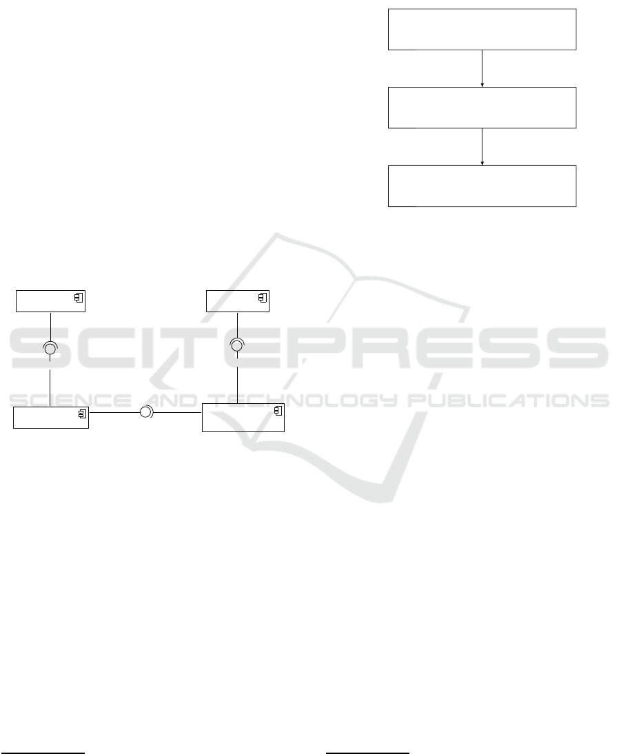
The implementation of the visualisation engine is
separated from the display unit and the ontology. This
makes the engine independ ent for future applications
as shown in the following co mponent diagram. A
completely assembled system can use Prot´eg´e as an
ontology editor to d ocument and generate the o nto-
logy. The AOWLN modelling engine extracts SWRL
rules th rough the OWL/SWRL API and produces a
diagram as an image file or as an interactive graph
(see Fig. 11).
<<component>>
Ontology Editor
<<component>>
Ontology
<<component>>
Display Unit
<<component>>
AOWLN Modelling
Engine
OWL/SWRL API
Graph Visualisation Framework
Display Ontology
gets diagram
extracts rules
models ontology
Figure 11: Component diagram.
5.2 Modelling Engine for Graphical
Abstraction (MEGA)
The impleme ntation is based on a three-layer-
approa c h has been developed to process rule data
from the ontology into the required graph format that
can be v isu alised (see Fig. 12). In Laye r 0, the SWRL
API
2
is the fundamental componen t. The SWRL
API (an extension of th e OWL API) reads the on-
tology and provides a set of SWRLAtoms. As the
SWRLAtom class from the SWRL API includes un-
necessary information for the visualisation, a custom
SWRL atom structure has been define d wh ic h is il-
lustrated as Layer 1. The createCustomSWRLAtoms()
method transforms the given SWRL atoms from the
SWRL API in to the custom SWRL atom structur e .
This makes it easier to focus on the most essential
2
See https://github.com/protegeproject/swrlapi - (acces-
sed on 06/01/2018)
informa tion for the visualisation. In a second step,
the createAOWLNElements() method creates a sepa-
rate list for both, AOWLN nodes and edges for La yer
2 based on the custom SWRL atoms in Layer 1. Ed-
ges contain references for a start and a target node.
6:5/$3,6:5/$WRPV
&XVWRP6:5/$WRPV
$2:/1(OHPHQWV
FUHDWH&XVWRP6:5/$WRPV
FUHDWH$2:/1(OHPHQWV
/D\HU
/D\HU
/D\HU
Figure 12: MEGA – t hree-layer-approach.
5.3 Prototype
The prototype has the following features: search and
select rules f rom the rule base, visualise the rules as
an AOWLN graph an d it includes an option to edit
and update a selected rule in the rule base. The pro-
totypical Prot´eg´e plugin is written in Java as both, the
Prot´eg´e environment and the SWRL API are also im-
plemented in Java. For the graph visualisation, we
make use of the open source library Graphviz.
3
6 CONCLUSION AND FUTURE
WORK
This p aper defines a graphical notation format for the
visualisation of SWRL rules and describes a prototy-
pical Prot´eg´e plugin for rule visualisation. AOWLN
offers mean s for visu alising all types of componen ts
of SWRL elements especially built-ins. For this, the
form of representation is a pair o f directed labelled
graphs to po rtray rule antecedent and consequent.
The implemented plugin offers options to search and
select rules from the rule base, visualise the ru le s
as an AOWLN grap h and includes an op tion to edit
and update a selected rule. As proof of concept
the plugin is currently used in an indu stria l digi-
tisation project which enabled several feedback loops.
Further fu nctions to im prove usability and error hand-
ling will make working with the visualisation tool
3
See https://www.graphviz.org/ - (accessed on
20/01/2018)
Aided OWL Notation (AOWLN): Conceptual Modelling and Visualisation of Advanced SWRL Rules
181
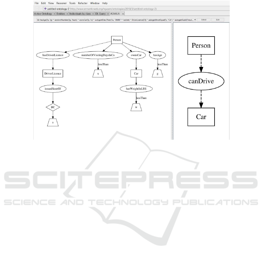
Figure 13: AOWLN Prot´eg´e Plugin – Protoype.
more efficient. Since the prototype was written as a
component inde pendent from both the ontology and
the display unit, it can ea sily be integrated into lar-
ger systems e.g. the plug in can easily be extended
to a graphical editor that allows for interactive cre-
ation and modification of SWRL rules. Further fo r-
malisation and generalisation to make the algorithm
work with arbitrary SWRL rules will be carried out.
We will provid e the source code for the AOWLN
project on g ithub. The repository can be acc essed
under the following URL: https://githu b.com/KITE-
Cloud/AOWLN
REFERENCES
Baader, F. (2003). The description logic handbook: Theory,
implementation and applications. Cambridge univer-
sity press.
Bak, J., Nowak, M., and Jedrzejek, C. (2013). Graph-based
editor for swrl rule bases. In RuleML (2). Citeseer.
Boley, H. (2013). Grailog 1.0: Graph-Logic Visualization
of Ontologies and Rules. In Proc. 7th International
Web Rule Symposium: Research Based and Industry
Focused (RuleML 2013), Seattle, Washington, USA,
volume 8035 of Lecture Notes in Computer Science,
pages 52–67. Springer.
Guarino, N., Oberle, D., and Staab, S. (2009). What is an
ontology? In Handbook on ontologies, pages 1–17.
Springer.
Hassanpour, S., O’Connor, M. J., and Das, A. K. ( 2009).
Axiom´e: A tool for the elicitation and management
of SWRL rules. In Proceedings of the 5th Internati-
onal Workshop on OWL: Experiences and Directions
(OWLED 2009), Chantilly, VA, United States, October
23-24, 2009.
Horrocks, I., Patel-Schneider, P. F., Boley, H., Tabet, S.,
Grosof, B., Dean, M., et al. (2004). Swrl: A semantic
web rule language combining owl and ruleml. W3C
Member submission, 21:79.
Kulakowski, K. and Nalepa, G. J. (2008). Using uml state
diagrams for visual modeling of business rules. In
Computer Science and Information Technology, 2008.
IMCSIT 2008. International Multiconference on, pa-
ges 189–194. IEEE.
McGuinness, D. L., Van Harmelen, F., et al. (2004). Owl
web ontology language overview. W3C recommenda-
tion, 10(10):2004.
KEOD 2018 - 10th International Conference on Knowledge Engineering and Ontology Development
182
