
Generic Architecture for Modular Real-time Systems in Robotics
Thomas Sch
¨
opping, Timo Korthals, Marc Hesse and Ulrich R
¨
uckert
Cluster of Excellence Cognitive Interaction Technology ‘CITEC’,
Bielefeld University, Inspiration 1, 33619 Bielefeld, Germany
Keywords:
Robotics, Modular Architecture, Real-time.
Abstract:
With the continuous progress in robotics and application of such systems in evermore scenarios, safety and
flexibility become increasingly important aspects and new designs should thus emphasize real-time capability
and modularity. This work points out all related topics for such an endeavor and proclaims to move from
conventional bottom-up design to more holistic approaches. Based on experience gained with the modular
mini robot platforms BeBot and AMiRo, a novel generic modular architecture is proposed that offers high
flexibility and system wide real-time capability.
1 INTRODUCTION
The concept of modularity in technical systems is
as old as engineering itself and has become increa-
singly important for development of modern robotic
and robot-like machines. When considering real-time
characteristics of a system or its components, modu-
larization becomes an even more complex problem,
as new dependencies arise that are hard to resolve.
Much effort was spent on development of modu-
lar software, such as middleware-based programming
(Yang and Duddy, 1996; Stanford-Clark and Hunke-
ler, 1999; Longchamp and Mondada, 2007; Quigley
et al., 2009; Wienke and Wrede, 2011) and according
hardware concepts (Br
¨
aunl, 2006; Zurawski, 2006),
but only few of these approaches take the whole de-
velopment process into account. Following modern
concepts of systems engineering, all domains need
to be considered simultaneously during the entire de-
sign process (Herbrechtsmeier, 2017). Later stages
of development may thus have requirements to ear-
lier ones, making one-directional design approaches
(e.g. waterfall) unfeasible. Instead, more sophistica-
ted methods should be applied in order to create safe
and future-proof systems.
With our modular mini robot platforms BeBot
(Herbrechtsmeier et al., 2009) and AMiRo (Her-
brechtsmeier et al., 2012; Herbrechtsmeier et al.,
2016; Herbrechtsmeier, 2017), we had the chance to
gain plenty experience in developing and using mo-
dular systems. These robots have been designed from
scratch, starting with the architecture, realizing the
hardware, up to implementing a software framework,
and are frequently used in university contexts. This
way we encountered many challenges from both de-
veloper and user perspective, like realizing the mo-
dular structure, providing easy to use interfaces and
actually implementing applications that take full ad-
vantage of the platform’s features. With this work
we thus want to contribute the lessons learned to the
community, point out yet insufficiently investigated
topics in this regard, and propose a generic architec-
ture that can be applied to a wide range of systems.
The ultimate goal of our proposed architecture is to
enable the development of highly modular systems,
which, despite their modularity, satisfy real-time re-
quirements and are still easy to handle.
This work is structured as follows: Section 2 pre-
sents current state of the art and various topics that
need to be considered when developing new systems.
Starting with a brief definition of the term “real-time”
(2.1), the domains hardware (2.2), protocols (2.3) and
software (2.4) are addressed right after. In section 3
a generic architecture for modular real-time systems
is presented. All important design matters are refer-
red back to, starting with topology (3.1), to interfaces
(3.2), up to protocols used (3.3). Finally, a conclusion
and future prospect are given in section 4.
2 STATE OF THE ART
With the advent of the Internet of Things (IoT) an in-
creasing number of low-priced but powerful single-
Schöpping, T., Korthals, T., Hesse, M. and Rückert, U.
Generic Architecture for Modular Real-time Systems in Robotics.
DOI: 10.5220/0006899304030410
In Proceedings of the 15th International Conference on Informatics in Control, Automation and Robotics (ICINCO 2018) - Volume 2, pages 403-410
ISBN: 978-989-758-321-6
Copyright © 2018 by SCITEPRESS – Science and Technology Publications, Lda. All rights reserved
403

board computers like Arduino
1
, Raspberri Pi
2
, and
Nvidia Jetson
3
are available. There already exist se-
veral robot platforms that are entirely built up from
such devices, like the latest version of TurtleBot
4
.
Unfortunately, those systems suffer from the magni-
tude of interfaces and protocols that any device may
or may not support. Using off-the-shelf IoT hardware
requires either to implement a wide range of commu-
nication standards, or the number of applicable devi-
ces is restricted. On the contrary, a well-defined archi-
tecture allows to develop hardware specifically desig-
ned for a system, avoiding unneeded features and op-
timizing resource requirements in every regard. Pro-
fessional applications furthermore demand for archi-
tectures which exactly define the minimum and max-
imum capabilities of modules. This is especially true
when real-time characteristics of a whole system, not
just single components, are of importance for system
integrity and safety (Stankovic, 1988; Shin and Ra-
manathan, 1994; Br
¨
aunl, 2006; Zurawski, 2006).
For development of highly modular platforms like
BeBot or AMiRo conventional approaches are not
sufficient. Such systems require more holistic met-
hods (e.g. V-Model or PRINCE2) that allow depen-
dencies backwards in the development process (e.g.
hardware design depends on software). Moreover, ar-
chitecture design needs to take future, yet unknown
use cases into account, but the resulting system must
still be realizable regarding technical means. In the
end, a reasonable trade-off between complexity of de-
sign and flexibility for applications must be defined.
This section hence addresses the several domains that
should be considered when developing new systems.
Previously, however, the term “real-time” is discus-
sed, since it is an important characteristic of architec-
tures this work refers to.
2.1 About “Real-Time”
The concept of real-time computer systems already
emerged in mid-20th-century and was discussed in-
tensively by various authors (Stankovic, 1988; Shin
and Ramanathan, 1994; Br
¨
aunl, 2006; Zurawski,
2006). Unfortunately, the term is commonly misu-
sed as an “equivalent to fast computing” (Stankovic,
1988, p. 11) but should actually refer to determinism
and predictability of technical systems.
The fundamental idea of real-time systems is pre-
dictability of required resources, most importantly
1
https://www.arduino.cc/en/Main/Products/
2
https://www.raspberrypi.org/products/
3
http://www.nvidia.com/
4
http://www.turtlebot.com/
time, to execute a task. While latency, the time ac-
tually consumed by a task, is the most obvious pro-
perty, another important one is jitter, the amount of
temporal variance. Many tasks are periodic and need
to be executed repeatedly at a certain rate. In practice
it is very hard, if not impossible, to achieve this rate
exactly, but the amount of jitter must be assessable
for real-time systems. The reason why real-time cha-
racteristics of technical systems are important is that
violating the expected values may have severe conse-
quences, which must be strictly prevented.
Compliance to such constraints is an especially
challenging task when it comes to modular systems.
As it is the idea of modularity, dependencies between
components should be minimal, preferably even non-
existent. The specific real-time behavior of individual
modules, however, influences a system as a whole,
which makes predictability of modular systems hard
to achieve. Whereas real-time characteristics of a gi-
ven system configuration can be calculated straight
forward, any modification (i.e. adding/removing a
module) requires a complete recalculation of those
properties and possibly introduces violations of the
real-time requirements of already present modules.
2.2 Hardware
As the hardware is the foundation of any system and
can not easily be changed afterwards, it is of major
importance to anticipate as many use cases as possi-
ble during development. For modular systems, where
third parties may add custom modules in the future,
it is not possible to specify all upcoming applications
in detail. Instead, the wanted properties of a system
architecture should be defined first and only then the
actual realizability is considered. Although this dom-
ain primarily refers to mechanical and electrical inter-
faces, the most fundamental attribute of any modular
architecture is its topology. It defines in which way
modules can or must be arranged and therefore has
strong impact on the applicability of the architecture
and extensibility of the implementing systems.
2.2.1 Topology
This work distinguishes between two types of topolo-
gies: system topology and network topology. The for-
mer describes the physical and logical arrangement of
modules in a system and must specify the following
attributes:
• arrangement (e.g. linear, tree, star, ring, etc.)
• hierarchy (e.g. linear, tree, none)
• mandatory modules (e.g. for power supply) and
their position in the system
ICINCO 2018 - 15th International Conference on Informatics in Control, Automation and Robotics
404

• mechanical link between modules
The network topology on the other hand must define
the architecture regarding:
• number of interfaces and their properties
• communication topologies (point-to-point, linear,
star, ring, mesh, etc., or combinations)
• requirements for modules (e.g. mandatory inter-
faces or minimum processing performance)
• limitations (e.g. maximum number of modules or
maximum wire length)
At the beginning of the development process, the fa-
vored system topology should be defined first. Se-
cond, the network topology is specified accordingly.
Only then the actual tools (i.e. interfaces) are selected
to implement the concept. Since this third step must
take technical limitations into account, it might turn
out that the original idea is not feasible. In this case
the topologies need to be modified until a satisfactory
solution is found, resulting in an iterative process.
2.2.2 Mechanical Connection
The way how modules are mechanically connected to
each other depends on the application scenario. Mini
robots, for instance, will probably not face as high for-
ces as cars and hence requirements regarding stability
are rather low. On the one hand the electrical con-
nection between modules must be specified in terms
of which connectors are used to carry power and sig-
nals. On the other hand mechanical features need to
be defined, too:
• symmetric or asymmetric connection
• rigid or flexible link
• additional screws/clamps for mechanical stability
• easy to reproduce or proprietary solution
2.2.3 Electrical Interfaces
This work refers to inter-module interfaces only, as
external ones (e.g. USB ports) are implemented by
each module individually and are not defined by the
system architecture. In general, all interfaces can
be divided into three types: power supply, real-time
communication, and non-real-time communication.
Power supply, obviously, must be implemented
with a bus topology in order to provide a uniform in-
terface at any position in the system. The most impor-
tant consideration at this point is, which voltages are
available and what minimum and maximum currents
must be provided.
Bus signals are suited for real-time communica-
tion in modular systems, because transmission latency
does not significantly increase when modules are ad-
ded. Since predictable transmission latency is a com-
mon necessity in industrial contexts (e.g. automotive
industry), many solutions exist, such as CAN (ISO
11898, 2015) or FlexRay (ISO 17458, 2013). There
are significant differences between those regarding
performance, complexity and topology, though, that
must be considered when defining the system archi-
tecture.
A drawback of real-time capable interfaces in ge-
neral is a relatively low gross bandwidth of about
0.1 Mbit/s to 10 Mbit/s (ISO 17458, 2013; ISO
11898, 2015). Many modern applications require
huge amounts of data to be transferred through the
system (e.g. video streams), so that data rates of
100 Mbit/s or more are desired. Unfortunately, such
interfaces (e.g. Ethernet) are typically limited to
point-to-point connections, demanding for additional
switching and routing hardware. This is not only ex-
pensive, but also comes at higher power consumption
and limited real-time capabilities, since for modular
systems the number of hops can only be specified by
an upper bound. Although there exist modified ver-
sions of Ethernet that facilitate high-bandwidth real-
time communication, a common standard needs yet to
be defined (Felser, 2005; Steinbach et al., 2011).
2.3 Protocols
Although protocols rather depend on software than
hardware, this topic should already be kept in mind
during architecture design. The reason for this is that
they may have strong impact on the real-time capa-
bilities of a system and the efficient use of interfa-
ces. The following example illustrates how decisions
on this level effect hardware design. After that, some
protocols for CAN and FlexRay with different advan-
tages and disadvantages regarding complexity and ef-
ficiency (which may be important details when desig-
ning a new system) are briefly described.
2.3.1 Top-down Dependencies
Most high-level interfaces require some initialization
(i.e. starting drivers) and thus are only available some
time after system startup. Hence, these can not be
used to detect whether all modules are fully initialized
and ready for communication, leading to a chicken-
and-egg problem. One solution is to use the most ba-
sic interface: single wire GPIO signals. Those can
be handled natively by any digital hardware, from lo-
gic gates to microcontrollers, up to SoCs and FPGAs.
However, since usage of such signals must be well-
defined for multiple situations (i.e. startup, synchroni-
zation, shutdown, emergency stop) an according pro-
Generic Architecture for Modular Real-time Systems in Robotics
405

tocol is required. Then again, this protocol may use an
arbitrary number of these signals and can have special
requirements regarding polarity and timing, or even
combine GPIOs with further, more sophisticated in-
terfaces. As a result, the hardware must provide the
required features and thus the development process
depends on the protocol used.
2.3.2 Real-time Protocols
The popular real-time interfaces CAN and FlexRay
in their original forms feature very different proto-
cols. CAN uses priority masks and bitwise arbitra-
tion to facilitate priority-based message transmission.
In terms of real-time characteristics this is not opti-
mal, because any participant in the network can easily
stall communication by permanently sending messa-
ges with high priority.
FlexRay subdivides time into cycles, which com-
prise a static and a dynamic part. The former uses a
calendar with multiple slots participants can allocate
for precise time-triggered communication. The latter
can be used for event-based transmissions and opera-
tes similarly to CAN. While FlexRay offers better pre-
dictability, the frequency for periodic communication
is defined by the cycle length and unoccupied slots in
the static part result in a waste of bandwidth.
Since CAN is more flexible than FlexRay, many
additional protocols have been developed in order to
improve its real-time characteristics. For example,
TTCAN (Leen and Heffernan, 2002) achieves good
results for periodic communication, whereas FTT-
CAN (Pedreiras and Almeida, 2000) is more flexible
but latency is less predictable. RTCAN (Migliavacca
et al., 2013) even outperforms FlexRay in terms of ef-
ficiency by differentiation between hard-, soft-, and
non-real-time messages (HRT, SRT, and NRT). It fea-
tures high temporal determinism of HRT communica-
tion, is still very flexible, and can achieve an optimal
net/gross bandwidth ratio.
2.4 Software
While hardware is the foundation of any system, soft-
ware is the key element that brings it to life. This
topic must not be underestimated, since any system
is only as good as the software that exploits its fe-
atures. Nevertheless, it can not compensate for bad
decisions made during architecture and hardware de-
sign. In order to motivate and empower software en-
gineers to apply state-of-the-art methods to a certain
system, there are many things to consider that develo-
pers need and expect for a comfortable and productive
work flow.
First and foremost, the initial hurdle must be mi-
nimal and no profound knowledge of the whole sy-
stem should be required for writing new code. A
well designed software architecture can help develo-
pers getting things done by providing multiple layers
of abstraction and well documented interfaces. Tool-
chains must be provided that are either commonly
well known or easy to learn. Especially if proprietary
solutions are used, according tutorials must be pro-
vided so developers can become acquainted with the
technology.
The software architecture must furthermore repre-
sent the structure of the modular hardware as well as
various conceptual areas, like layer (from low-level
drivers to high-level applications) and real-time vs.
non-real-time code. For projects that involve many
developers, a well structured software habitat is very
important, so new code is added in the correct place
and errors can be identified and fixed as quickly as
possible. The following sections address four impor-
tant areas of a software habitat.
2.4.1 Bootloader
Before a module can completely start up, a bootlo-
ader should take care of hardware initialization and
provide some additional functionality. The main tasks
are to set up voltage regulators so that power is provi-
ded to all local components and the rest of the system,
as well as a rudimentary module status/health check.
If a protocol for startup synchronization is defined,
the bootloader must implement this, too.
Another important (or at least helpful) purpose of
a bootloader is to provide options for installation of
software updates. Bootloaders can even be used to
remotely update the software for any other module in
the system via some communication interface during
an additional initialization stage. This is especially
useful if some modules are not trivial to access.
2.4.2 Operating System
Although this work emphasizes real-time capabilities,
not all modules must run real-time operating systems.
Those which incorporate sensors or actuators should
comply to real-time constraints, but modules designed
for processing only may well focus on performance
and thus omit all real-time related overhead. When
it comes to communication with the rest of the sy-
stem, however, the latter must respect the real-time
properties of interfaces and protocols used. Only re-
sources that are not allocated for real-time communi-
cation (e.g. remaining time slots in a calendar-based
protocol) may be used by non-real-time modules to
transmit data.
ICINCO 2018 - 15th International Conference on Informatics in Control, Automation and Robotics
406
2.4.3 Middleware
It is very common to use middlewares or according
protocols as central communication systems for mo-
dular architectures. In the last decades a great number
of such have been developed with CORBA (Yang and
Duddy, 1996), MQTT (Stanford-Clark and Hunkeler,
1999), and ROS (Quigley et al., 2009) probably being
the most popular ones. Using such tools has nume-
rous advantages:
• Compatible applications can be executed on any
module or system that runs the according middle-
ware, allowing for high code portability.
• A lot of software is already available and can be
integrated with minimal effort.
• Realization of further applications is simplified
due to the uniform interfaces and additional de-
bugging and profiling tools that most middlewares
provide, leading to high quality code but minimi-
zing development time.
The major issue with middlewares for real-time sys-
tems is that only very few solutions consider real-time
computing and thus most can not be used for accor-
ding tasks. Fortunately, there are exceptions to this
rule, such as Real-Time CORBA (Fay-Wolfe et al.,
2000) and the R2P middleware (Migliavacca, 2013).
2.4.4 Tools
Programming, deploying and analyzing of software
requires sophisticated tool-chains that ease these tasks
for developers. Such comprise compilers and inter-
preters for the programming languages used, as well
as debuggers and profilers. Furthermore, tools for
code documentation and version control (e.g. Subver-
sion or Git) are essential for modern development and
thus for understandable, reusable, and reliable high-
quality code. When developing high-level applicati-
ons for any system, it is also very helpful to provide a
simulation environment.
3 GENERIC ARCHITECTURE
While for small sized modular robots like BeBot and
AMiRo linear topologies suffice, systems with higher
complexity require a more generic architecture. The
herewith proposed solution results from experience
gained by developing and using these two platforms,
but wants to address not only mini robots but a wide
range of implementations and thus features high flex-
ibility in multiple regards. Most important aspects are
its low complexity but high flexibility and scalability
M1 M2
M3
M4
M5 M6
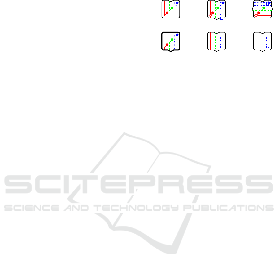
Figure 1: Example configurations of modules. All three
supported network topologies are depicted: red/solid:
point-to-point; green/dashed: linear and star bus;
blue/dotted: circular daisy-chain. Circles represent con-
nections to processing hardware, diamonds switching and
routing circuitry.
by supporting a variety of interfaces that allow for ap-
plicability in as many scenarios as possible.
The resulting architecture facilitates a hierarchical
tree system topology but still features three types of
network topologies, thereby supporting real-time as
well as high-bandwidth interfaces. The software fra-
mework is not characterized in this work, but the ha-
bitat of AMiRo can be used as reference (Herbrechts-
meier et al., 2016; Sch
¨
opping et al., 2018).
3.1 Topology
As depicted in figure 1, each module features exactly
one input and an arbitrary number of output connec-
tors (indicated by the arrow shapes in the borders).
The only exception to this rule are root modules like
M4, which must not have any inputs, or if so, those
must not be used. Outputs, however, do not need to
be occupied by child modules, so that unused con-
nectors are generally valid. Furthermore, the archi-
tecture supports three different communication topo-
logies: Point-to-point as a basic requirement for most
high-bandwidth interfaces, linear and star bus for real-
time communication, and circular daisy-chain sig-
nals. Whilst actual utilization of most interfaces is op-
tional and wires can just be connected through, daisy-
chain signals may be disrupted explicitly by nonsup-
porting modules like M6. In order to keep the signal
chain closed on unoccupied connectors, either exter-
nal adapters or internal bridges can be used (cf. M2
and M3 in figure 1).
Point-to-point connections link a module directly
to its parent and all its children. Although this topo-
logy allows for high transfer rates, sending data to a
more distant module requires additional routing logic.
The resulting hops lead to increased latency which
makes these interfaces unsuitable for real-time com-
munication in modular systems (cf. 2.2.3).
Bus connections on the other hand enable system
Generic Architecture for Modular Real-time Systems in Robotics
407
wide communication with almost constant latency. Of
course there is some minimal delay due to the elec-
trical signal propagation on the wires, but since such
interfaces usually trade their flexibility for low trans-
fer rates, these electrical latencies can be neglected.
A challenge with buses, however, are concurrent sen-
ding requests of multiple participants, as only one mo-
dule at a time can transmit data. Hence, this issue
needs to be resolved on a protocol level (cf. section
2.3.2).
The third communication topology supported by
the architecture is circular daisy-chain. It requires
both output and input for each link, but a module must
only use one of these signals, whereas the other one
is just propagated from connector to connector. Bran-
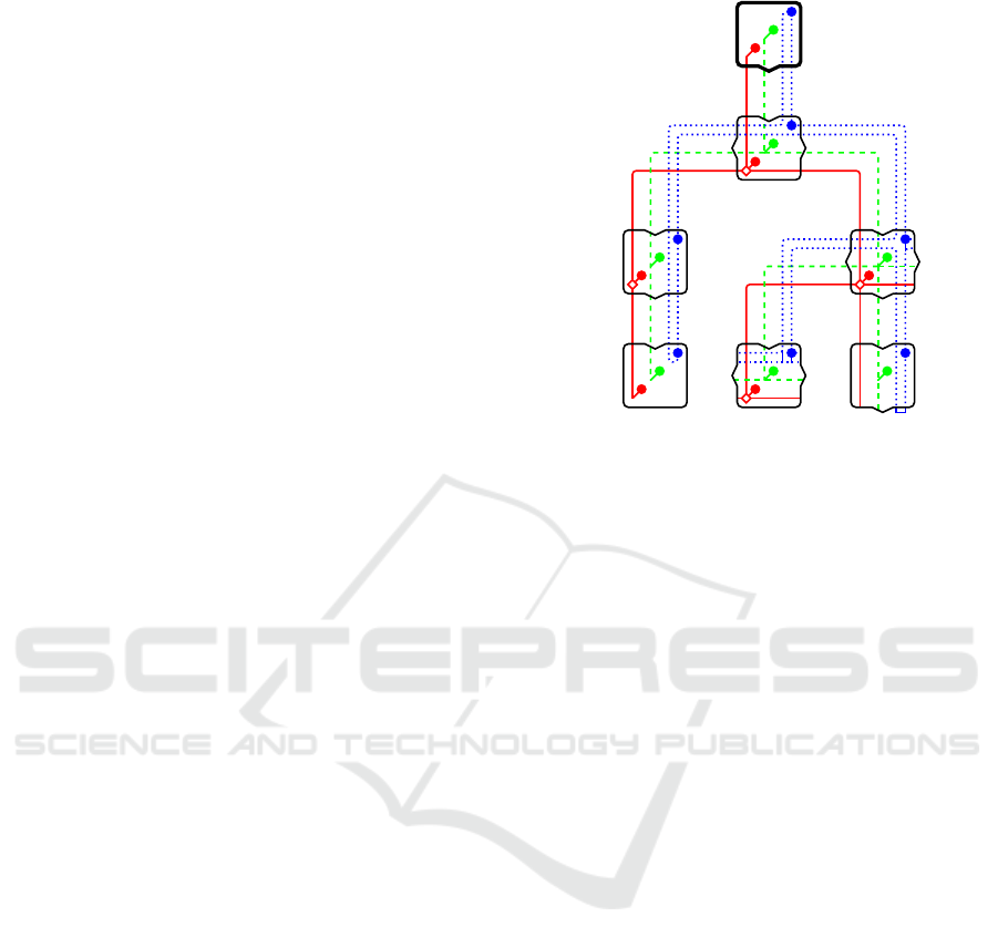
ching modules like M3 in figure 1 or B in figure 2
must pass the signal iteratively to all outputs and fi-
nally feed the wire back to the input connector. By
doing so, a hierarchy is introduced in the system to-
pology, which is not horizontal but vertical to the tree
structure. For the depicted example in figure 2, the
signal chain and thus the hierarchy is: A → B → E →
G → F → C → D and back to A, or in reversed order.
In general, all signals are optional if not defined
otherwise by the specific implementation. However,
the three network topology types need to be handled
in different ways in case a module does not imple-
ment the interfaces. Point-to-point connections must
be connected through and hence only modules with
exactly one input and one output can do so without
the need for further hardware. Bus signals, on the
other hand, can simply be split and passed on to all
output connectors. Finally, modules that do not im-
plement a daisy-chain must either disrupt the signal
or connect it through. The former solution allows to
detect whether all modules implement the according
signal, whereas for the latter the interface can still be
used by the rest of the system.
3.2 Interfaces
One goal of the proposed architecture is to keep the
hardware requirements for modules low but at the
same time provide sophisticated interfaces. As a re-
sult, only a small number of signals and communica-
tion standards are defined, some of which are optio-
nal, as described in the following.
3.2.1 Power Supply
Only the most common voltages (e.g. 3.3 V, 5.0 V
and 12 V) should be provided via the interconnect.
Specific implementations may define redundant wi-
res to differentiate between main supply and standby
power. The minimum and maximum currents must
A
B
C
D
E
F
G
Figure 2: Architecture with combined network topologies
(cf. figure 1). In this example the root module A has a
single output, D finalizes a branch as it has only an input, C
and G are one-to-one modules, and B, E and F are one-to-
many branching modules.
be defined by the implementation as well, where the
maximum formerly depends on the electrical speci-
fications of the connectors used. In addition to the
supply, according wires for ground must be provided
as well, of course.
3.2.2 Low-Level Control
In order to support basic system control and synchro-
nization, the interconnect must provide three GPIO-
based signals. Whilst two of these implement a bus
topology (wired-OR), the third facilitates a circu-
lar daisy-chain and defines the module hierarchy (cf.
section 3.1). Two additional signals are defined for re-
setting the whole system and to detect whether a child
module is attached. By definition of the architecture,
most of these signals are mandatory and must be im-
plemented by each module. The only exception is the
daisy-chain signal, but specific implementations may
define it to be mandatory as well.
3.2.3 Configuration & Debugging
As a widely supported interface, JTAG is part of the
interconnect specification but not mandatory. Howe-
ver, it is up to the implementation whether it is reali-
zed in a daisy-chain manner (IEEE 1149.1, 2013) or
star topology (IEEE 1148.7, 2009). For the former
case, modules must not disrupt the signal like M6 in
figure 1 does.
ICINCO 2018 - 15th International Conference on Informatics in Control, Automation and Robotics
408

3.2.4 Real-time Communication
Although it is a rather old real-time capable com-
munication interface, CAN is still commonly used
and widely supported. It requires no more than two
wires that carry a differential signal and can reach
a gross bandwidth of up to 1 Mbit/s. FlexRay is
a more recently developed alternative, but is not as
well supported as CAN yet. It uses one or two dif-
ferential pairs, can reach up to 10 Mbit/s per channel
and incorporates calendar-based communication for
better real-time characteristics. However, CAN-FD
(ISO 11898, 2015), an enhanced version of CAN, can
achieve a bandwidth similar to FlexRay and an even
better net/gross throughput ratio when using appropri-
ate protocols (cf. 2.3.2). Either of both solutions can
be used, but it then is defined as mandatory interface
for all modules in the system.
Both CAN and FlexRay require a specific termi-
nation of the differential signal at each end of the bus.
Usually this is realized by connecting both wires via
an according resistor, but this is not possible for mo-
dular systems. Every output connector of each mo-
dule may or may not be occupied by a child and hence
the actual end of a bus is not known beforehand. A
possible solution is to implement a Terminating Bias
Circuit (ISO 11783, 2007) in combination with the
control signal for child detection.
3.2.5 High-bandwidth Communication
The architecture furthermore specifies an Ethernet in-
terface for the interconnect (point-to-point). It not
only provides high bandwidth, but is also a fundamen-
tal requirement for many middlewares that do not sup-
port other interfaces, like ROS (Quigley et al., 2009)
or RSB (Wienke and Wrede, 2011). PCI Express may
be used as alternate or additional interface as well,
but complexity, power consumption and hardware- as
well as software support must be considered. Be-
cause such interfaces are quite demanding regarding
hardware design and processing, implementation of
high-bandwidth interfaces should be optional for in-
dividual modules.
3.3 Protocols
For well-defined system startup and shutdown as well
as synchronization during operation, an according
protocol must be specified and each module has to im-
plement it. Furthermore, if CAN is used for real-time
communication, it is recommended to use an additio-
nal protocol, which enhances the real-time characte-
ristics of the interface.
3.3.1 SSSP
One goal for AMiRo was to support a wide range
of modules that may comprise any computational
logic: low-cost microcontrollers as well as high-
performance SoCs and FPGAs. Due to this heteroge-
neity, the most basic common interface (i.e. GPIOs)
was used for synchronizing all modules during star-
tup, operation, and shutdown. The resulting Startup
Shutdown Synchronization Protocol
5
(SSSP) requires
no more than two wired-OR bus signals (cf. section
3.2.2). For enhanced features it supports two further
optional interfaces: An additional daisy-chain signal
and a bus (e.g. CAN or FlexRay). By its very low re-
quirements it is easy to implement but still offers ad-
vantageous features like initialization of the module
hierarchy during startup.
3.3.2 CAN Protocols
Some protocols that enhance real-time characteristics
of the CAN interface have already been presented in
section 2.3.2, each having its individual advantages
and disadvantages.In the end an appropriate trade-off
must be found, which again depends on the applica-
tion scenario of the implementation.
For the proposed architecture, however, RTCAN
is considered as preferable solution. It features high
flexibility, efficiency and good real-time characteris-
tics while complexity and resource requirements for
most participants are minimal. The only exception is
the node that keeps track of the schedule of HRT mes-
sages, which must host sufficient memory. Since the
proposed architecture defines a root module (cf. fi-
gure 2), this is the only one that needs to feature that
much memory, whereas all other modules may host
hardware with less resources.
4 CONCLUSION
With this work, an overview of the various domains
that need to be taken into account when developing
modular real-time systems was given. Since there is
no such thing as the ultimate solution, multiple ap-
proaches were pointed out, which all have their indi-
vidual advantages and drawbacks. Especially when it
comes to real-time systems, there are several issues
that need yet to be solved, such as standardized pro-
tocols and methods for initialization (and shutdown),
and a common real-time Ethernet standard.
5
https://opensource.cit-ec.de/projects/amiro-os/wiki/
SSSP/
Generic Architecture for Modular Real-time Systems in Robotics
409

Based on the aforementioned discussions and ex-
periences gained with the robot platforms BeBot and
AMiRo, a novel generic architecture was presen-
ted. By combining three types of network topologies
(point-to-point, linear/star bus, and circular daisy-
chain) it offers high flexibility and performance while
achieving real-time capability throughout the whole
system. With SSSP being part of the architecture spe-
cification, startup and shutdown procedures are well-
defined and the system can easily be synchronized du-
ring operation. Moreover, the topological layout fa-
cilitates a hierarchy which can be determined during
startup and utilized thereafter for any purpose. Future
systems can easily implement this architecture due to
its low requirements and benefit from its high flexibi-
lity.
ACKNOWLEDGEMENTS
This work was supported by the Cluster of Ex-
cellence Cognitive Interaction Technology ‘CITEC’
(EXC 277) at Bielefeld University, which is funded
by the German Research Foundation (DFG).
Many thanks to Stefan Herberchtsmeier for his ef-
forts developing the platforms BeBot and AMiRo.
REFERENCES
Br
¨
aunl, T. (2006). Embedded robotics. Springer.
Fay-Wolfe, V., DiPippo, L. C., Cooper, G., Johnston, R.,
Kortmann, P., and Thuraisingham, B. (2000). Real-
time CORBA. IEEE Transactions on Parallel and
Distributed Systems.
Felser, M. (2005). Real-time ethernet-industry prospective.
Proceedings of the IEEE.
Herbrechtsmeier, S. (2017). Modell eines agilen Lei-
terplattenentwurfsprozesses basierend auf der inter-
disziplin
¨
aren Entwicklung eines modularen autono-
men Miniroboters. PhD thesis.
Herbrechtsmeier, S., Korthals, T., Sch
¨
opping, T., and
R
¨
uckert, U. (2016). AMiRo: A Modular & Custo-
mizable Open-Source Mini Robot Platform. ICSTCC.
Herbrechtsmeier, S., R
¨
uckert, U., and Sitte, J. (2012).
AMiRo - Autonomous mini robot for research and
education. In Advances in Autonomous Mini Robots:
Proceedings of the 6-th AMiRE Symposium.
Herbrechtsmeier, S., Witkowski, U., and R
¨
uckert, U.
(2009). BeBot: A modular mobile miniature ro-
bot platform supporting hardware reconfiguration and
multi-standard communication. Communications in
Computer and Information Science.
IEEE 1148.7 (2009). IEEE Standard for Reduced-Pin
and Enhanced-Functionality Test Access Port and
Boundary-Scan Architecture.
IEEE 1149.1 (2013). IEEE Standard for Test Access Port
and Boundary-Scan Architecture.
ISO 11783 (2007). Tractors and machinery for agriculture
and forestry – Serial control and communications data
network.
ISO 11898 (2015). Road vehicles – Controller area network
(CAN).
ISO 17458 (2013). Road vehicles – FlexRay communicati-
ons system.
Leen, G. and Heffernan, D. (2002). TTCAN: a new time-
triggered controller area network. Microprocessors
and Microsystems.
Longchamp, V. and Mondada, F. (2007). ASEBA , an event-
based middleware for distributed robot control. Com-
munications.
Migliavacca, M. (2013). The R2P framework for robot pro-
totyping: methodological approach, hardware modu-
les, and software components. PhD thesis, Politecnico
di Milano.
Migliavacca, M., Bonarini, A., and Matteucci, M. (2013).
RTCAN : a Real-Time CAN-Bus Protocol for Robotic
Applications. In ICINCO.
Pedreiras, P. and Almeida, L. (2000). Combining event-
triggered and time-triggered traffic in FTT-CAN: Ana-
lysis of the asynchronous messaging system. Interna-
tional Workshop on Factory Communication Systems.
Quigley, M., Conley, K., Gerkey, B., FAust, J., Foote, T.,
Leibs, J., Berger, E., Wheeler, R., and Mg, A. (2009).
ROS: an open-source Robot Operating System. ICRA.
Sch
¨
opping, T., Korthals, T., Hesse, M., and R
¨
uckert, U.
(2018). AMiRo: A Mini Robot as Versatile Teaching
Platform. Proceedings of the 9th International Confe-
rence on Robotics in Education.
Shin, K. G. and Ramanathan, P. (1994). Real-Time Com-
puting: A New Discipline of Computer Science and
Engineering. Proceedings of the IEEE.
Stanford-Clark, A. and Hunkeler, U. (1999). MQ telemetry
transport (MQTT).
Stankovic, J. A. (1988). Misconceptions about real-time
computing: A serious problem for next-generation sy-
stems. Computer.
Steinbach, T., Korf, F., and Schmidt, T. C. (2011). Real-
time Ethernet for automotive applications: A solution
for future in-car networks. Digest of Technical Papers
- IEEE International Conference on Consumer Elec-
tronics.
Wienke, J. and Wrede, S. (2011). A middleware for col-
laborative research in experimental robotics. 2011
IEEE/SICE International Symposium on System Inte-
gration, SII 2011.
Yang, Z. and Duddy, K. (1996). CORBA: A Platform for
Distributed Object Computing. SIGOPS Oper. Syst.
Rev.
Zurawski, R. (2006). Embedded Systems Handbook. CRC
Press.
ICINCO 2018 - 15th International Conference on Informatics in Control, Automation and Robotics
410
