
Influence of Human Limb Motion Speed in a Collaborative
Hand-over Task
Matteo Melchiorre, Leonardo Sabatino Scimmi, Stefano Mauro and Stefano Pastorelli
Department of Mechanical and Aerospace Engineering, Politecnico di Torino, C.so Duca degli Abruzzi 24, Turin, Italy
Keywords: Collaborative Robotics, Human Robot Hand Over, Trajectory Planning, Motion Tracking.
Abstract: The paper analyses a possible cooperative task between a human operator and a robot. Operator and robot are
interfaced by Microsoft Kinect® which is used to detect the position of an upper limb of the operator. The
robot is driven by a control algorithm designed to track the hand of the human and to obtain a hand-over in
the final part of the trajectory. The paper describes the algorithm and shows its performance with different
velocities of the limbs by means of tests carried out in a simulation environment.
1 INTRODUCTION
The most recent manufacturing scenario is moving
towards the integration of robot’s and human’s
workspace in which the cooperation assumes a central
role and defines a specific field of research for
human-assistance application. Thus, the most
fascinating challenge is to safely approach the
machines to the human, especially in the industrial
context, in order to reduce the risk of injuries and the
completion of repetitive tasks, respectively lightening
the workers fatigue and stress. Moreover, the
introduction of collaborative robots (cobots) in the
workstations is synonymous of flexibility and
changeability. All the mentioned advantages clearly
represent a potential increase in terms of productivity.
There are many works contributing to fully focus
the state of the art in Human Robot Collaboration
(HRC). Bo et al. (2016) present a brief description of
the classical robotics industrial application, while a
more detailed overview on HRC is given by Kruger
et al. (2009). The latter identifies an interesting
classification of cooperative systems, distinguishing
the “workplace sharing systems” from “workplace
and time sharing systems”. In the “workplace sharing
systems” human and robot perform separated task
within a shared environment and the interaction
between them is limited to collision avoidance; the
“workplace and time sharing systems” indicates the
possibility to jointly handle objects in a level much
deeper than just the avoidance of collision. This work
stands in the second type of systems and it is focused
on the study of human-robot interaction (HRI) in
handing-over applications, describing the results
obtained in the development of an algorithm to drive
the end effector of the robot towards the human hand
while carrying out a collaborative task.
In literature there are several works introducing
HRI in industrial environments. Michalos et al (2014)
describe a case study whose final level is the
execution of the same assembly task by the robot and
the human being in direct physical interaction;
Cherubini et al (2016) propose a full and concrete
example of an assembly application in which a LBR
iiwa is controlled in real time using a RGB camera
and admittance control in order to execute the task
safely with the human operator. Zahe and Roesel
(2009) also discuss an assembly process, performed
by human and robot, monitored by various sensors.
All the cited examples move towards the industrial
application, thus suffers the very restrictive safety
constraints which close to a complete integration of
human and robot: tasks are carried out sequentially
and there is not cooperation at the level of hand-over
the objects to be assembled.
Other works studies the HRI without strictly
referring to industrial application. They are useful to
understand the closer relationship between humans’
behaviour and robot’s capability while assisting them.
Agah and Tanie (1997) investigate the problem of a
human receiving object from a mobile manipulator,
which is controlled through an algorithm based on
fuzzy logic, simulating a simple 2D model of both
human limb and robotic 3DOFs arm. Huber et al
(2008) describe the interaction of human and robot in
Melchiorre, M., Scimmi, L., Mauro, S. and Pastorelli, S.
Influence of Human Limb Motion Speed in a Collaborative Hand-over Task.
DOI: 10.5220/0006864703490356
In Proceedings of the 15th International Conference on Informatics in Control, Automation and Robotics (ICINCO 2018) - Volume 2, pages 349-356
ISBN: 978-989-758-321-6
Copyright © 2018 by SCITEPRESS – Science and Technology Publications, Lda. All rights reserved
349
a handing-over task, driving the manipulator along
fixed trajectories and discussing the influence of the
robot velocities in people perception. A similar study
is proposed in (Shibata et al, 1997), where the
relationship between the human-human and human-
robot hand-over is analysed, also considering the
influence of the final hand-over position of the robot
end effector and the human hand.
This work aims to contextualize the hand-over
task in a collaborative environment, investigating the
behaviour of a cobot following the human operator
hand, which is tracked by means of a multi-vision
system. Additionally, in order to integrate the hand-
over with the cooperative task, the collision
avoidance will be also considered to evaluate the total
computation time for a complete collaborative
algorithm (Mauro et al., 2017), (Mauro et al., 2018).
The collaborative space consists of a working
table over which it is placed a collaborative robot; a
man is standing in front of the robot and he is
supposed to hand-over a component in different
positions on the table. The trajectory of the hand of
the human is detected by two Microsoft Kinect
®
, and
the measured signal is used to update the trajectory of
the robot. Tests are carried out in a simulated
environment including a kinematic model of the Kuka
LBR iiwa R820 robot, which is interfaced with actual
signal experimentally measured. The results show the
trajectory followed by the robot in several tests,
considering different limb velocities and different
final positions for the hand of the operator.
The paper is structured as follow: in section 2 the
layout of the shared workspace is presented,
introducing the task and the elements which
characterize the collaborative space. Section 3
describes the hand-following algorithm together with
the simulation tools; the experimental setup and the
method for spatial synchronization are described in
section 4. Finally, section 5 discusses the main results
of the experiments.
2 THE COLLABORATIVE TASK
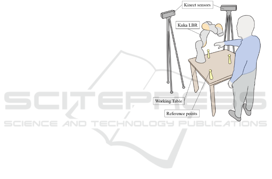
The collaborative operation is carried out in a
workspace which is shared between the human
operator and the robot. The task is performed on a
working table and the human operator is standing in
front of it, along one of its long sides. The robot is
installed at the opposite side of the table, as shown in
Figure 1.
Two Microsoft Kinect
®
are displaced on the same
side of the robot and detect the motion of the upper
limbs of the human operator. The use of two sensors
allows to prevent full occlusion cases, since the robot
could represent an obstacle for human tracking while
executing the task. In order to ensure the correct
positioning of the points detected by the motion
capture system, 3 reference points are displaced in the
workspace and are used to build the reference frame
ℱ
when the system is initialised.
The robot is only virtual and human-robot
interaction is simulated in Matlab by interfacing the
experimental data measured by the motion capture
system with a model of the robot, which is operating
in the same virtual workspace.
Figure 1: Shared workspace.
The performed task consists in making possible a
hand-over between the hand of the man and the end-
effector of the robot. The robot is driven in order to
track with its end effector the position of the hand of
the human operator until these two parts come in
contact.
The tests are carried out considering the case in
which the man extends its right upper limb to reach a
hand-over area on the workbench. According to the
position detected by the motion tracking system, the
robot reacts and drives its end effector towards the
final position reached by the hand of the operator.
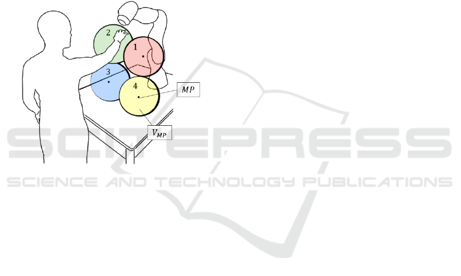
In order to study a potentially collaborative task,
the hand-over can happen in four different portions of
the working space, identified as meeting volumes
, which are represented in Figure 2. These
volumes are shaped as four spheres centred in the
ideal meeting points MPs and are chosen so that they
almost entirely cover the volume reachable by the
human with his extended arm, standing beside the
workbench.
ICINCO 2018 - 15th International Conference on Informatics in Control, Automation and Robotics
350
Five different velocities are considered for the
motion of the human limb. However, as the
trajectories should certainly change if an operator
performed the same motion with different velocities,
only one movement towards each of the MPs was
acquired. The time history of the position of the
human skeleton joints identified by the Kinect sensor
was then modulated by scaling the total time T times
0.6, 0.8, 1.3 and 1.6. Thus, slower and faster motions
were simulated. Finally, the signal was interpolated
and resampled to consider the effect of the Kinect
refresh time. The sampling frequency was assumed to
be 30 Hz, as provided by datasheet and verified
during experimental tests.
Figure 2: Meeting points and their
volumes.
3 HAND-FOLLOWING
ALGORITHM
3.1 Motion Planning
The problem of observing and following a moving
target has already been studied in different
applications. Houshangi (1990) gave interesting
results on grasping a moving object with a 6DOF
manipulator using vision. In this section the method
of motion planning based on separation of the
direction and size of velocity in the working space is
adopted, using the inverse kinematics algorithm and
a principle similar to (Bing & Xiang, 2008), (Dong &
Zhu, 2016).
The available data from the sensors is the position
of the human hand
measured with a sampling time
Δ
. The position
and orientation
of the end-
effector are also known from forward kinematic.
Starting from this information, the operational space
error
between the desired and actual end-effector
position at sample k, can be written using the
generalized vectors
,
and
,
as
=
,
−
,
=
,
,
(1)
,
=
,
,
,
=
,
,
(2)
where
,
is the end-effector desired final
orientation, which in each test is assumed to be equal
to the initial value. To drive the end-effector towards
the target, intuitively its linear velocity is set as:
,
=
,
=
,
(3)
with a direction
pointing the target and a
magnitude proportional to the position error through
the constant depending on the application (Figure
3). The same approach is used to define the angular
velocity, which is modelled proportional to the
orientation error written in terms of unit quaternion
,
(Siciliano et al, 2009). The generalized velocity
vector of the end-effector becomes:
,
=
,
,
(4)
Thus, the joint velocity vector at time k is
obtained by inverting the Jacobian:
=
,
,
(5)
At the end, joints position is computed by means
of first order integration. The dynamic behaviour of
the robot was also considered by modelling the
velocity response of each servo axis as a first order
system.
For the purpose of this paper, it is reasonable to
limit the maximum value of the linear velocity of the
end-effector to 0.25ms
. This choice is justified by
the desire to study a collaborative task (ISO10218-
1:2011 “Safety requirements for industrial robots”)
meeting the requirements for a good hand-over
(Jindai et al, 2006). Moreover, a safety margin is
introduced to let the end-effector stop at a distance
from the human hand (Figure 3).
Influence of Human Limb Motion Speed in a Collaborative Hand-over Task
351
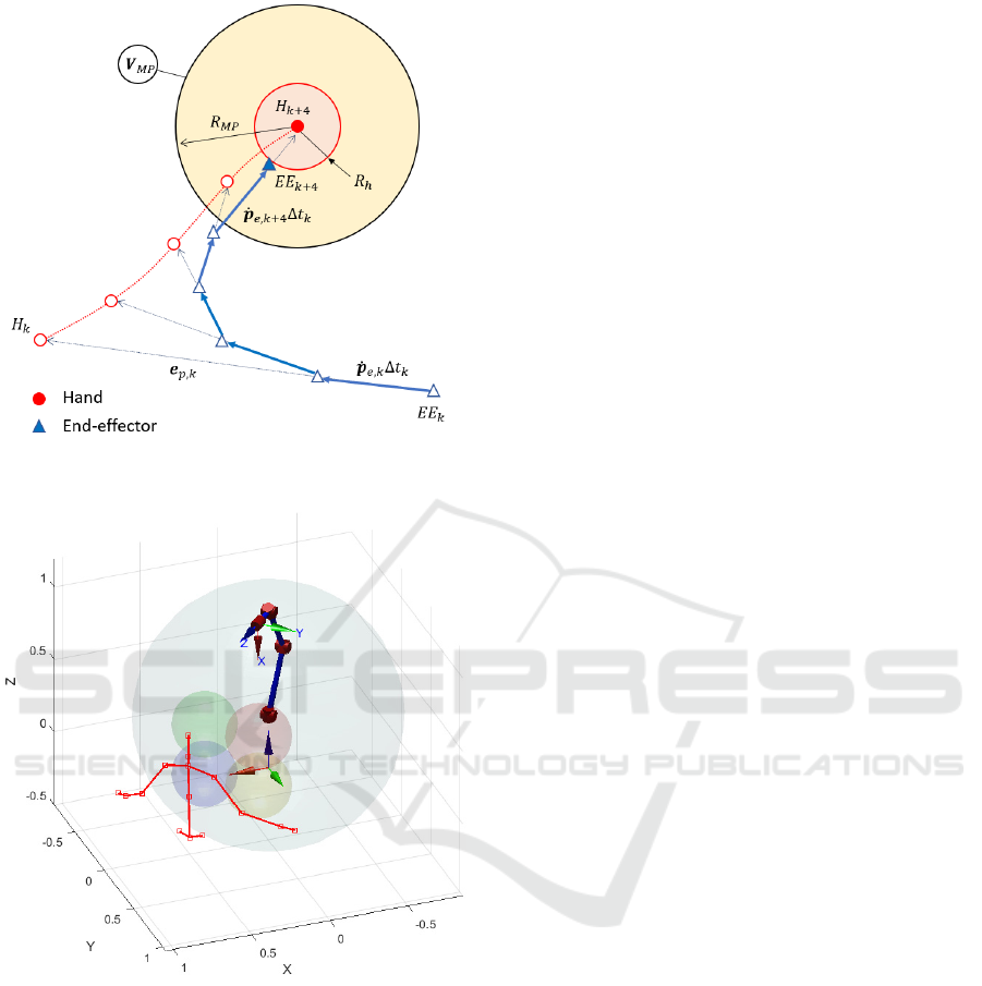
Figure 3: Schematics of the motion planning.
Figure 4: Matlab simulation environment.
3.2 Algorithm and Simulation Tools
The simulation algorithm must implement the motion
planning while processing the skeleton data coming
from the two Kinect sensors. Moreover, to analyse the
total time required for computation in a collaborative
environment, the effect of a collision avoidance based
on potential fields is added to (4) as described in the
work of Mauro et al. (2018).
The interaction of robot with the human is
simulated in Matlab. Figure 4 shows the kinematic
model of the robot built using the Robotics Toolbox
(Corke, 2017) in its initial pose. In the same figure are
also plotted the stick diagram of the human upper
body, the operational space of the robot
(grey
transparent sphere), the four meeting volumes
introduced in Figure 2, the reference frame ℱ
(at the
base of the robot) and the end-effector frame ℱ
.
Table 1 schematize the algorithm: once the
skeleton
,
and
,
at sample time
are available
from both sensors A and B, an optimization is carried
out to refine the signal with the duplex Kinect
approach (Yeung, Kwok & Wang, 2013); then the
initial configuration from the LBR kinematic model
is obtained and the hand-following starts only if the
human hand results in the operational space of the
robot
. If the latter condition is met, the following
and avoiding velocities,
,
and
,
respectively,
are computed to finally obtain the new robot
configuration
through inverse kinematics. The
robot stops to point toward the target if both the hand
of the human and the end-effector meet in one of the
ideal meeting point ranges
, represented by means
of four spheres. Notice that the hand-over can happen
in any point inside the coloured spheres.
The specifications of the iiwa R820, obtained
from the data sheet of the KUKA LBR, are included
in the model. Thus, calculations are made considering
the joints angle limits and their velocity range. The
joint velocity outputs from the hand-following
algorithm are integrated, updating the robot
configuration until a new human hand configuration
is processed, it means with the Kinect sampling rate
Δ
=1/30 s.
Table 1: Algorithm structure.
1.
for ∈
2.
,
,
,
3.
,
⟶
,
4.
⟶
,
,
,
5.
if
,
∈
&&
,
,
,
∉
6.
⟶
,
7.
⟶
,
8.
,
=
,
+
,
⟶
,
9.
=
,
10.
=
+
Δ
11.
=
12.
else
=
13. end
14. end
ICINCO 2018 - 15th International Conference on Informatics in Control, Automation and Robotics
352
4 EXPERIMENTAL TESTING
4.1 Spatial Matching
The multiple sensor approach, combined with the
need for simulating the presence of the manipulator,
requires that the two operators of the collaborative
task, i.e. human and robot, are correctly identified in
a common reference frame ℱ
. The ℱ
must be
physical and opportunely built, positioned and
oriented in the shared volume so that it can be easily
recognized by the two sensors and the human.
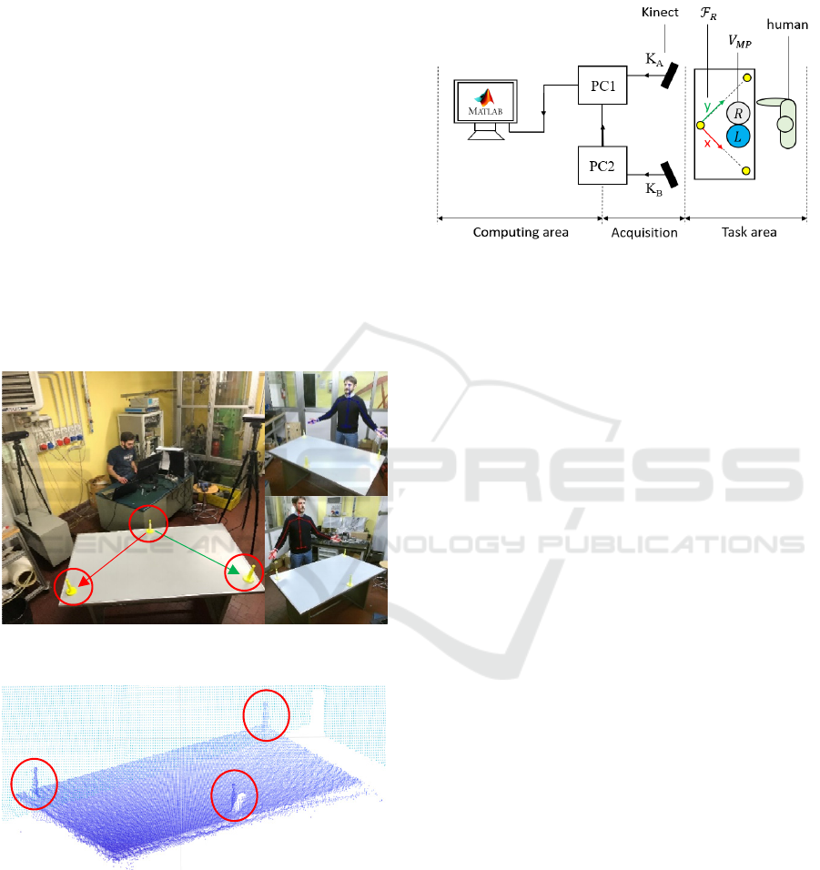
The Kinect allows to measure spatial coordinate
of objects within its field of view (FOV) in terms of
point cloud. Watching this principle and by
considering the depth camera resolution, we designed
three suitable solid references, characterized by a
narrow-conical support with a spherical protruding
tip of a 10 mm radius. It was observed that it is easy
to distinguish the spherical references in the point
cloud to locate them in the Kinect frame (Figure 5-6).
Figure 5: Lab set-up for spatial matching.
Figure 6: References in the Kinect point cloud.
Figure 5 shows the ℱ
placed on the table that
represents the workbench. Although the absence of
the physical robot might seem a limiting factor, if the
coordinates of the base of the manipulator with
respect to the ℱ
is conveniently defined, it is easy to
arrange the meeting points (MPs) as a subset of the
LBR operational space. In this case we assume the
base of the robot coincident with the ℱ
so that the
MPs fill the working volume between the two
operators (Figure 7).
Figure 7: Scheme of the experimental hardware.
4.2 Experimental Set-up
In Figure 7 the schematics of the experimental tools
and hardware are presented. The test area can be
divided in three main groups which communicate to
produce, acquire and process data. The human
operator is standing in front of the table, opposite the
ℱ
origin in which is located the robot, defining the
task area. The measurements are performed by the
two Kinect sensors, whose FOVs cover the entire
volume defined by the task area. Finally, the
hardware for data processing is placed outside the
views of the depth cameras.
Microsoft Kinect SDK support only one sensor at
a time, thus we used two computers to acquire the
skeleton data. The PCs are wired so they can send and
receive signals each other. In particular, PC1 is
designated to handle the start/stop acquisition triggers
for the sensors to make the sampling synchronous.
Moreover, it collects the raw points from Kinect A
and B, executing the algorithms for skeleton
optimization and target pursuit. For this purpose, we
use two computers with i7-6700 processor and 32 GB
RAM.
To inspect the human-robot interaction in
different conditions, the tests are conducted at
different MPs and velocities of the human hand. This
is a powerful approach because it encloses the
characteristics of a collaborative task. Thus, the study
of different MPs, also taking into account the speed
factor, will give information on the behaviour of the
operators who are completing the heterogeneous task.
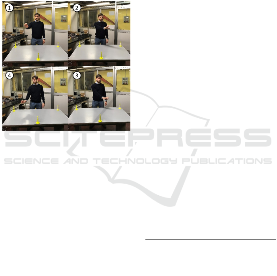
In the experiments the human identifies the MPs
by observing two references on the workbench that
indicates the projections of the meeting volumes
(Figure 7), the latter being inside the operational
y
x
Influence of Human Limb Motion Speed in a Collaborative Hand-over Task
353
space of the robot as mentioned in the previous
section. Said projections are named L (left) and R
(right). If the shoulders and the hips are then assumed
as reference for the z coordinate of the MPs, the
meeting volumes
are completely defined. The
frames in Figure 8 illustrate the four movements
corresponding to the various MPs.
Figure 8: Tested movements of the human hand. The round
labels identify the number assigned to each test.
5 RESULTS
Table 2 summarises the simulation parameters used
to generate the data presented in this section, while
Figure 9 contains the main results of this work.
Figure 9 (a) shows the simulation frames of test 1
with the original values of the hand velocity. In the
first frame (left) the hand starts moving and the robot
doesn’t react because the target is outside its
operational space; when the hand is inside the grey
volume (second and third frames) the algorithm
animates the robot. Finally, the end-effector meets the
hand in the meeting volume to accomplish the hand-
over task.
To better understand the hand-over time
behaviour, Figure 9 (b) illustrates the distance
between the end-effector and the human hand versus
the original times of tests 1 and 3. If the hand-over
happens within the volume of test 1, it can be
observed that the hand waits less than a second until
seeing the robot entering in the
. In test 3 there’s
a more significant delay due to the different
position since the end-effector linear velocity is
limited to 0.25 ms
-1
for this collaborative task. Notice
also that the hand-over happens in all cases at the
distance
=0.1m.
To analyse the human limb velocity effect on the
hand-over sequence, in Figure 9 (c) the time is
normalized over the period T, which represents the
hand motion total time. For test 1, focusing on the
interval within the two operators stop, the red curves
show different delays in terms of percentage. For
example, the 0.6T test shows the human waiting
more than 2.5T until the robot reaches the meeting
point. Furthermore, with a 1.6T movement, the hand
and the robot would access the meeting volume at
almost similar times, representing an interesting
scenario. The blue curves of test 3 reveals also
different behaviours as function of the velocities.
Here the delay goes from 1.7T to almost 4T, the latter
representing the worst case. Therefore, the higher the
human limb velocity to reach the meeting point, the
longer is the task-cycle to accomplish hand-over.
In Figure 9 (e) the hand-over positions for each
test, from the point of view of the human operator, are
presented. Finally, Figure 9 (d), shows the path of the
end-effector and the hand for each test and for
different velocities of the human limb. The results
show that the robot paths are very close even varying
the period T, which is the time the hand needs to reach
the meeting points and to stop. In particular, the robot
trajectories of test 4 almost coincide, while test 3 is
the most susceptible. Thus, in the defined task, the
human velocity does not noticeably influence the end-
effector trajectories and, most important, the hand-
over final relative position of the hand and the robot
does not change.
Table 2: Simulation parameters and times.
= 820mm
= 200mm
= 100mm
= [/4,−/6,0,−/3,0,/3,0]
=10
,
=0.25ms
.= 5
.= 10
.< 1
ICINCO 2018 - 15th International Conference on Informatics in Control, Automation and Robotics
354
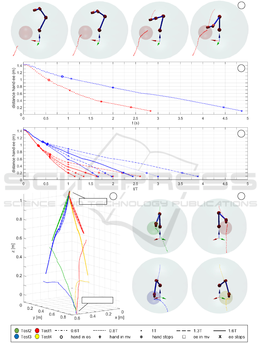
Figure 9: a) Test 1 simulation frames; b) distance hand-ee with original sampling time in test 1 and 3; c) distance hand-ee
with normalized time for different values of human limb velocity in test 1 and 3; d) paths of the hand and the ee in the four
tests; e) hand-over frames.
a
b
c
d
e
t=0.6 s
t=1.1 s
t=1.7 s
t=2.8 s
ee starting point
hand starting point
Influence of Human Limb Motion Speed in a Collaborative Hand-over Task
355

6 CONCLUSIONS
In this paper an algorithm, useful for a potentially
cooperative task between a human and a robot, is
presented. The work contains all the elements which
characterize a collaborative space and focuses on the
hand-over without restricting the robot to walk
predefined paths: the algorithm controls the cobot to
permit to the end-effector to reach the hand of the
human operator in any point of a dedicated
exchanging area.
Experimental tests have been performed to
validate the methodology. In these tests, the human
hand moves towards four distinct positions with
different velocities. Different total times of human
limb motion towards the meeting points do not affect
the robot paths, but they influence the delay in the
hand-over task.
Future works will involve different modelling of
the end-effector linear velocity to move the robot with
a human-like profile, for example pursuing a
minimum-jerk profile or a simple ball-shaped one
(Flash et al., 1985). The prediction of the human
movements, not considered in this work, will be
another important point to refine the algorithm.
REFERENCES
https://www.iso.org/standard/51330.html
Agah, A., and Tanie, K, 1997. Human Interaction with a
Service Robot: Mobile-Manipulator Handing Over an
Object to a Human. In Proceedings of the 1997 IEEE
International Conference on Robotics and Automation,
New Mexico.
Bing, W., and Xiang, L., 2008. A Simulation Research on
3D Visual Servoing Robot Tracking and Gaspring a
Moving Object. In 15
th
International Conference on
Mechatronics and Machine Vision in Practice, pp. 362-
367.
Bo, H., Mohan, D. M., and Azhar, M., 2016. Human Robot
Collaboration for Tooling Path Guidance. In IEEE
International Conference on Biomedical Robotics and
Biomechatronics, pp. 1340-1345.
Cherubini, A., et al, 2016. Collaborative manufacturing
with physical human-robot interaction. In Robotics and
Computer-Integrated Manufacturing, 40, pp. 1-13.
Corke, P. I., 2017. Robotics, Vision & Control:
Fundamental Algorithms in Matlab, Springer. London,
2
nd
edition.
Dong, G., and Zhu, Z. H., 2016. Incremental visual servo
control of robotic manipulator for autonomous capture
of non-cooperative target. In Advanced Robotics, 30:22,
pp. 1458-1465.
Flash, T., and Hogan, N., 1985. The Coordination of Arm
Movements: An Experimentally Confirmed
Mathematical Model. In The Journal of Neuroscience,
5(7), pp. 1688-1703.
Houshangi, N., 1990. Control of a robotic manipulator to
grasp a moving target using vision. In Proceedings.,
IEEE International Conference on Robotics and
Automation, pp. 604-609.
Huber, M., et al., 2008. Human-Robot Interaction in
Handing-Over Tasks. In Proceedings of the 17
th
IEEE
International Symposium on Robot and Human
Interactive Communication, pp. 107-112.
Jindai, M., Shibata, S., Yamamoto, T., and Watanabe, T.,
2006. A Study on Robot-Human System with Consider-
ation of Individual Preferences. In JSME International
Journal Series C Mechanical Systems, Machine
Elements and Manufacturing, 49, pp. 1033-1039.
Kruger, J., Lien, T. K., and Verl, A., 2009. Cooperation of
human and machines in assembly lines. In CIRP
Annuals, Manufacturing Technology, 58, pp. 628-646.
Mauro, S., Pastorelli, S., and Scimmi, L.S., 2017. Collision
Avoidance Algorithm for Collaborative Robotics. In
Int. J. of Automation Technology, 11(3):481-489.
Mauro, S., Scimmi, L. S., and Pastorelli, S., 2018. Collision
Avoidance System for Collaborative Robotics. In
Mechanisms and Machine Science, 49:344:352.
Michalos, G., et al., 2014. ROBO-PARTNER: Seamless
Human-Robot Cooperation for Intelligent, Flexible and
Safe Operations in the Assembly Factories of the
Future. In Procedia CIRP, 23, pp. 71-76.
Shibata, S., Sahbi, B. M., Tanaka, K., and Shimizu, A.,
1997. An Analysis of The Process of Handing Over An
Object and Its Application to Robot Motions. In IEEE
International Conference on Systems, Man, and
Cybernetics.
Siciliano, B., Sciavicco, L., Villani, L., and Oriolo, G.,
2009. Robotics: Modelling, Planning and Control,
Springer. London.
Yeung, K. Y., Kwok, T.H., and Wang, C. L., 2013.
Improved Skeleton Tracking by Duplex Kinects: A
Practical Approach for Real-Time Applications. In
Journal of Computing and Information Science in
Engineering, 13(4).
Zaeh, M., and Roesel, W., 2009. Safety Aspects in a
Human-Robot Interaction Scenario: A Human Worker
Is Co-operating with an Industrial Robot. In FIRA
2009: Progress in Robotics, pp. 53-62.
ICINCO 2018 - 15th International Conference on Informatics in Control, Automation and Robotics
356
