
Characteristics of a Mower Robot with Swing Mower Mechanism by
Simulation
Ryota Suzuki
1
and Yoshihisa Uchida
2
1
Graduate School of Engineering, Aichi Institute of Technology, Yachigusa 1247, Yakausacho, Toyota 470-0392, Japan
2
Aichi Institute of Technology, Yachigusa 1247, Yakausacho, Toyota 470-0392, Japan
Keywords: Mower Robot, Swing Mower Mechanism, Lever-crank Mechanism, Swath, Torque, Velocity, Centroid
Movement, Sideslip, Energy Consumption, Operation Time.
Abstract: This study proposes a new mower robot with a swing mower mechanism for advantages such as a string
trimmer and a wide swath. The proposed swing mower mechanism is designed for installation in the main
body of a four-wheel drive mower robot AMR-D01. The AMR-D01 had overall dimensions as follows: 0.60
m length, 0.50 m width, and 0.30 m height; it weighs 28 kg and maximum velocity is 1.29 m/s. The swing
mower mechanism is based on the lever-crank mechanism and translates motor rotation into swing of the
rotary blade. We model the mechanism and simulate the characteristics of the centroid movement, sideslip,
energy consumption, and operation time to evaluate the swing mower mechanism. The robot velocity is
controlled to prevent the occurrence of the unmown spot. Swath is increased from 0.24 m to 0.62 m by 2.58
using the mechanism. The operation time is also decreased by 1/2.58. The swing mower mechanism does not
have much influence on the robot movement. The change of the static friction coefficient and the slope angle
also does not have much influence on the sideslip of the robot under the present conditions. The energy
consumption increases with the increasing robot velocity.
1 INTRODUCTION
A string trimmer is light and small and can easily
treat; therefore, the trimer is widely used. However, it
requires heavy work, takes time to work, and have a
serious safety issue (Hanidza, 2013). Thus, the string
trimer automation is needed to overcome these
problems. Various string trimmer robots, such as
handle-, passenger-, and remote-type robots, are used
until now.
HAMMER KNIFE (OREC, 2018) and HR663
(YAMABIKO, 2018) are commercialized as the
handle type. These trimmers are very convenient, but
the user must control behind the machine. Ride on
Brush Cutter “RABBIT”(OREC, 2018), RMJ800
(YAMABIKO, 2018), ZHM1520 (ZENOAH, 2018),
and Mid-mower (Jun, 2008) are commercialized and
proposed as passenger type. These are very useful for
large area, but user must ride and drive the machine
and machine is heavy weight. Miimo (Honda, 2018)
and HUSQVARNA AUTOMOWER® 315
(Husqvarna, 2018) are commercialized and proposed
as the remote type. These trimmers are small and safe,
but are mainly for the lawn.
Challenges for practical application of mower
robot are obstacle detection and avoidance,
miniaturization for efficiency and optimization, path
planning and tacking, ability to move on rough terrain,
and efficiency of grass cutting. Several researchers
have proposed to overcome these problems.
Most mower robots are intended to operate on
agricultural land, garden, rice field and river bed.
However, such areas are not free from interactions
with humans, whose safety and legal positions must
be considered. Christiansen et.al. (Christiansen,
2017) proposed a sensor platform in autonomous
mowing operation to detect a human using several
cameras. This platform is for a tractor, thus, the entire
platform is large. In contract, small robots for
agriculture are paying attention for efficiency and
optimization (Basu, 2018). Path planning methods for
agriculture robot are proposed (Urrea, 2015, Wang,
2014, Ohkawa, 2014, Hameed, 2014). These methods
are useful for mower robot. Improvement of
movement performance and efficiency of grass
cutting on small robot are remaining issues.
We develop remote-controlled mower robots in
our laboratory. The developed mower robot is usable
even on a slope ground. However, they have
Suzuki, R. and Uchida, Y.
Characteristics of a Mower Robot with Swing Mower Mechanism by Simulation.
DOI: 10.5220/0006856903070312
In Proceedings of the 15th International Conference on Informatics in Control, Automation and Robotics (ICINCO 2018) - Volume 2, pages 307-312
ISBN: 978-989-758-321-6
Copyright © 2018 by SCITEPRESS – Science and Technology Publications, Lda. All rights reserved
307
disadvantages, such as small swath and long
operation time. In addition, grass, which is not
mowed, hit against the front body of the robot
because its blade diameter is smaller than the width
of the robot body. This study develops a new mower
robot, which has the goal to reach convenience like a
string trimmer, has a wide swath, and an autonomous
travel.
This study proposes a new mower robot with a
swing mower mechanism for convenience like a
string trimmer and a wide swath. Three methods,
namely multiple-blade, large-blade, and swing-blade
methods, are used to acquire a wide swath. The
multiple-blade method can have an unmown spot in-
between blades. The large blade needs a high cutting
energy. Although the mechanism of the swing-blade
method is complex, it can use an existing blade. Thus,
we selected the swing-blade method by the swing
mower mechanism. We discuss the centroid
movement for static characteristics, sideslip for
dynamic characteristics, energy consumption, and
operation time.
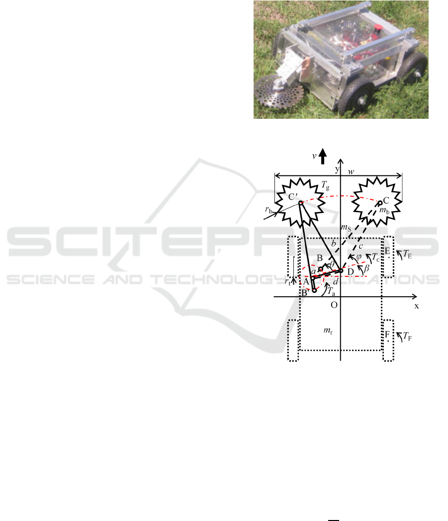
2 MOWER ROBOT
The proposed swing mower mechanism was designed
for installation in the main body of the four-wheel
drive mower robot, AMR-D01. The robot had main
dimensions of 0.60 m length, 0.50 m overall width,
and 0.30 m overall height. It had a total weight of 28
kg and a maximum velocity of 1.29 m/s (Figure 1).
AMR-D01 consisted of a blade for cutting and the
main body. The blade was attached to the front of the
main body. The control system of the robot consisted
of a control circuit, a drive circuit, motors for drive,
blade and swing, and sensors. The robot received the
control signal from the remote controller. The robot
then properly moved using feedback control.
The swing mower mechanism was based on the
lever-crank mechanism and translated motor rotation
into swing of the rotary blade (Figure 2). The rotation
of link AB was translated into the swing of link CD
with joint D as a supporting point using the drive
motor for this mechanism installed at joint A. In this
mechanism, the r
b
radius rotary blade installed at
joint C swings from side to side. The counter
clockwise angles of links AB and CD with datum line
AD are θ and φ , respectively. For the symmetric
swing, the mechanism was rotated by β.
The AMR-D01 parameters are as follows: mass of
the robot main body m
r
=26.4kg; mass of the blade
m
b
=1.6 kg; mass of the swing mower mechanism
m
S
=0 kg; radius of the wheel r
t
=0.1 m; radius of the
blade r
b
=0.12 m; and lengths of the link a = 0.060 m,
b= 0.430 m, c = 0.382 m, and d = 0.139 m. In this
case, the angle β is 0.25 rad from the calculation. The
x and y axes are set as shown in Figure 2. The origin
O is at the center of the robot body.
Figure 1: Photograph of the mower robot AMR-D01.
Figure 2: Schematics of the mowing robot.
3 SIMULATION
We modeled the mechanism and simulated the
characteristics of the centroid movement, sideslip,
energy consumption, and operation time to evaluate
the swing mower mechanism.
The angular velocity of link AB, θ
, is given as
follows to prevent the unmown spot occurrence:
(1)
where, is the robot velocity.
θ
=
π
r
b
ICINCO 2018 - 15th International Conference on Informatics in Control, Automation and Robotics
308
The swath w by swing is obtained as follows:
(2)
where, φ
max
andφ
min
are the maximum and
minimum of φ, respectively.
Considering the moment of inertia and the load
torque from grass T
g
, torque T
c
that occurs in link CD
by the swing blade is given as Eq. (3).
(3)
The torque required link, AB, T
a
is obtained as
follows using the angular velocity ratio of links AB
and CD:
(4)
The required torque of the swing motor is
calculated using Eq. (4).
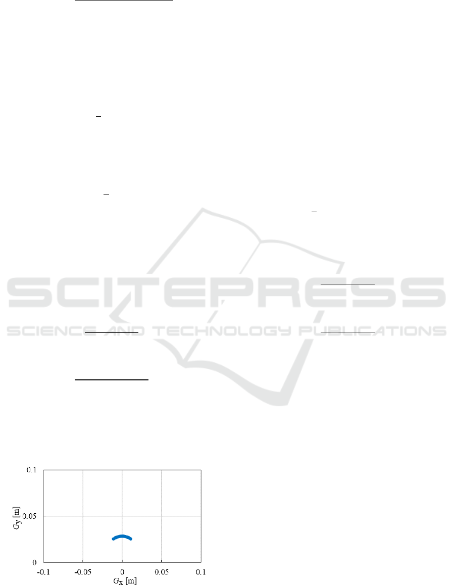
We evaluate the centroid movement for the static
characteristics. Assuming that the mass of the swing
mower mechanism is negligible, m
S
=0, because this
mass is much smaller than the mass of the body. The
centroid of the robot G
(G
x
, G
y
) is calculated from
the following equations:
(5)
(6)
Figure 3 shows the centroid movement in a period of
swing. The results show that the centroid movement
is small against the robot size. Thus, the swing mower
mechanism does not have much influence on the
robot movement.
Figure 3: Characteristic of the centroid movement of the
robot.
We discuss herein the sideslip for the dynamic
characteristics. The torque around joint D at the front
and rear tires (i.e., T
E
and T
F
, respectively) are
expressed as follows:
(7)
(8)
where, μ
0
is the static friction coefficient; N is the
normal reaction; q
1
is the distance between joint D (0,
y
1
) and the contact point of the front tire, E (x
1
, y
2
);
is the distance between joint D (0, y
1
) and the
contact point of the rear tire, F (x
1
, y
3
). The centroid
movement is small against the robot size; hence, the
normal reaction N is given by Eq. (9) as follows:
(9)
where, α is the slope angle, and g is the gravity
acceleration. Using the Pythagorean theorem, the
distances of q
1
and q
2
are given as follows:
(10)
(11)
The sideslip does not occur when the sum of the
torque at each tire is larger than torque T
c
. For
simplicity, variable Q is defined as follows:
(12)
The sideslip of the robot does not occur when Q is
positive. Figure 4 shows the minimum value of Q
during one period as a function of the static friction
coefficient for various slope anglesα. Variable Q
min
increases with the increasing friction coefficient for
all slope angle conditions. Figure 5 presents variable
Q
min
as a function of the slope angle. Variable Q
min
decreases with the increasing slope angle. Variable
Q
min
is a negative value when μ
0
is smaller than 0.05.
These results indicate that the change of μ
0
and
α does not have much influence on the sideslip of the
robot under actual possible use conditions.
w=2r
b
+c
2{1- cos (φ
max
-φ
min
)}
T
c
=m
b
φ
1
2
r
b
2
+c
2
+T
g
T
a
=
φ
θ
c
G
x
=
m
b
ccos
φ+
β
m
r
+m
b
G
y
=
m
b
csin
φ+β
+y
1
m
r
+m
b
T
E
=μ
0
Nq
1
T
F
=μ
0
Nq
2
,N=
1
4
m
r
+m
b
gcosα
q
1
=
x
1
2
+y
2
-y
1
2
q
2
=
x
1
2
+y
1
-y
3
2
,Q=2
T
E
+T
F
-T
c
Characteristics of a Mower Robot with Swing Mower Mechanism by Simulation
309
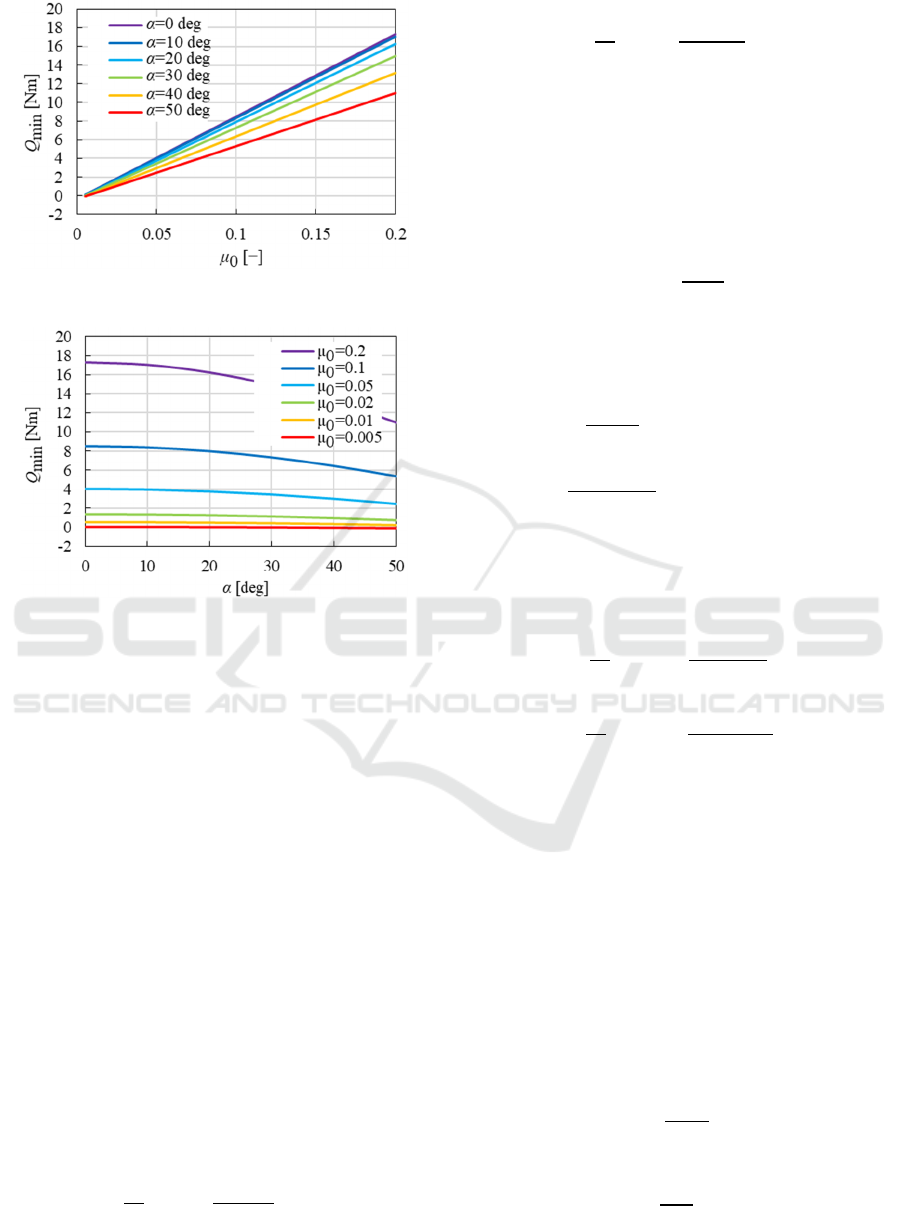
Figure 4: Q
min
as a function of the static friction coefficient.
Figure 5: Q
min
as a function of the slope angle.
The proposed method has the swing mower
mechanism that needs additional energy. Therefore,
we perform a comparison of the characteristics with
and without the swing mower mechanism to evaluate
the robot’s energy consumption.
The energy consumption of the existing mower
robot, P
A
, is expressed with the energy consumption
of the drive motor for moving, P
At
and the blade
motor for the rotary blade,P
Ab
.
(13)
In the same manner, the energy consumption of the
robot with the swing mower mechanism, P
S
, is
expressed as follows with the energy consumption of
the drive motor, P
St
, blade motor, P
Sb
, and swing
motor for the swing mower mechanism, P
Ss
:
(14)
The energy consumption of each drive motor,
P
At
and P
St
, is expressed as follows:
(15)
(16)
where, K
t
n/T
is the rotation number–torque gradient;
K
t
T
is the torque constant; K
t
n
is the rotation number
constant; n
At
and n
St
are the rotation numbers of each
drive motor; T
At
and T
St
are the torques of each drive
motor; and t
A
and t
S
are the operation times of the
robot. n
At
and n
St
are given as Eq. (17),
(17)
where, i
t
is the speed reduction ratio of the gear head.
T
At
and T
St
are given as Eqs. (18) and (19),
respectively,
(18)
(19)
where, μ is the dynamic friction coefficient, and η
t
is
the transmission efficiency.
The energy consumptions of the blade motor, P
Ab
and P
Sb
, are expressed as follows:
(20)
(21)
where, K
b
n/T
is the rotation number–torque gradient;
K
b
T
is the torque constant; K
b
n
is the rotation number
constant; n
b
is the rotation number of the blade motor;
and I
b
is the motor current.
The energy consumption of the swing motor,
P
Ss
, is expressed as follows:
(22)
where, I
S
is the swing motor current, and V
S
is the
input voltage.
The rotation number n
Ss
and the torque T
Ss
of the
swing motor are expressed as follows:
(23)
(24)
P
A
=
P
At
+
P
Ab
P
S
=
P
St
+
P
Sb
+
P
Ss
P
At
=
π
30
n
At
T
At
+
K
t
n/T
T
At
2
K
t
T
K
t
n
t
A
P
St
=
π
30
n
St
T
St
+
K
t
nT
⁄
T
St
2
K
t
T
K
t
n
t
S
n
At
=n
St
=
30i
t
π
r
t
T
At
=
m
r
+m
b
i
t
η
t
sin α +μ cos α
gr
t
T
St
=
m
r
+m
b
+m
S
i
t
η
t
sin α +μ cos α
gr
t
P
Ab
=
π
30
n
b
K
b
T
I
b
+
K
b
T
K
b
n/t
I
b
2
K
b
n
t
A
P
Sb
=
π
30
n
b
K
b
T
I
b
+
K
b
T
K
b
nT
⁄
I
b
2
K
b
n
t
S
P
Ss
=
I
S
V
S
t
S
n
Ss
=
30θ
i
S
π
T
Ss
=
1
i
S
η
S
T
a
ICINCO 2018 - 15th International Conference on Informatics in Control, Automation and Robotics
310
where, i
S
is the speed reduction ratio of the gear head,
and η
S
is the transmission efficiency of the swing
motor. I
S
is calculated using these equations and the
motor specifications.
The simulation conditions are as follows:
n
b
=5631rpm , I
b
= 1.35 A,V
S
= 24 V,
K
t
n/T
=8.69×10
3
rpm/Nm, K
t
T
=25.9×10
3
Nm/A,
K
t
n
=369rpm/V, K
b
n/T
=20.6×10
3
rpm/Nm,
K
b
T
=24.3×10
3
Nm/A, and K
b
n
=393rpm/V.
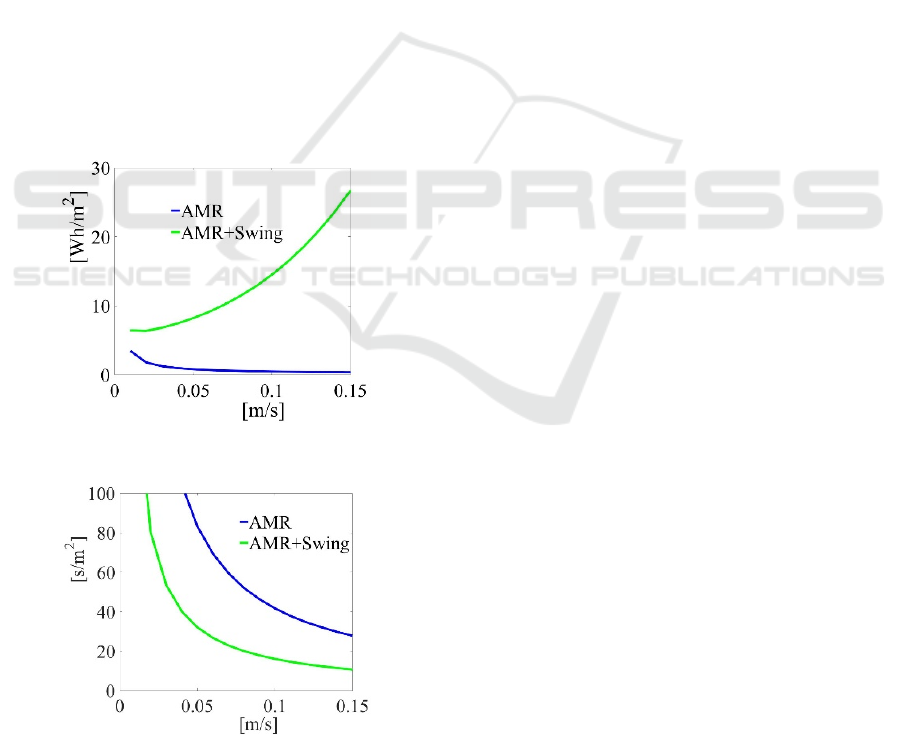
Figure 6 shows the typical results of the energy
consumption per square meter at the conditions of
α
=0 and μ
=0.3. A comparison with and without the
swing mower mechanism shows that the energy
consumption with the swing mower mechanism is
larger than the energy consumption without the swing
mower mechanism.
Figure 7 shows the characteristics of the operation
time per square meter with and without the swing
mower mechanism. Using the mechanism, the swath
is increased from 0.24 m to 0.62 m by 2.58. Therefore,
the operation time per square meter is also decreased
by 1/2.58 under the condition of the same robot
velocity. The swing mower mechanism effectively
increases the swath and decreases the operation time.
Figure 6: Results of the energy consumption.
Figure 7: Results of the operation time.
4 CONCLUSIONS
We proposed the swing mower mechanism for a
mower robot. We modeled the mechanism and
simulated the characteristics of the centroid
movement, sideslip, energy consumption, and
operation time to evaluate the swing mower
mechanism.
The findings obtained are as follows:
1) The robot velocity and the angular velocity of
link AB were controlled to prevent the unmown
spot occurrence.
2) The centroid movement was small against the
robot size. Thus, the centroid movement did not
have much influence on the robot movement.
3) We also discussed the sideslip for the dynamic
characteristics. The change of the static friction
coefficient and the slope angle also did not have
much influence on the sideslip of the robot
under the present conditions.
4) We performed a comparison of the
characteristics with and without the swing
mower mechanism to evaluate the energy
consumption of the robot. The energy
consumption with the swing mower mechanism
was larger than the energy consumption without
the swing mower mechanism.
5) The swath was increased from 0.24 m to 0.62 m
by 2.58. Therefore, the operation time per
square meter was also decreased by 1/2.58. The
swing mower mechanism effectively increased
the swath and decreased the operation time.
For the future work, we will build the mower
robot and experimentally evaluate the robot. For the
autonomous travel, we will construct a self-location
estimation system running with Kalman filter using
GNSS and inertial sensors. Moreover, the load torque
will be applied to control the blade motor by the robot
velocity related to a change in the amount of grass.
ACKNOWLEDGEMENTS
This work was partially supported by JSPS
KAKENHI Grant Number JP17K06279 and a special
research grant from Aichi Institute of Technology,
Japan.
,
v
,v
,P
A
, P
S
,t
A
, t
S
Characteristics of a Mower Robot with Swing Mower Mechanism by Simulation
311

REFERENCES
Hanidza, T., Jan, A., Abdullah, R., Ariff, M., 2013.
Procedia, Social and Behavioral Sci., Vol. 90, pp. 661–
672.
OREC, 2018. http://www.orec-jp.com/en/products.html.
YAMABIKO, 2018. http://www.yamabiko-corp.co.jp
/kioritz/products/category/detail/id=9549.
YAMABIKO, 2018. http://www.yamabiko-corp.co.jp
/kioritz/products/category/detail/id=2108.
ZENOAH, 2018. http://www.zenoah.co.jp/int/products
/flail-mowers/zhm1520/.
Jun, H., Choi, Y., Lee, C., Kang, Y., 2008. Engineering in
Agriculture, Environment and Food Vol. 1, No. 1, pp.
39–44.
Honda, 2018. http://world.honda.com/powerproducts-
technology/miimo/.
Husqvarna, 2018. http://www.husqvarna.com/us/products
/robotic-lawn-mowers/automower-315/967623405/.
Christiansen, P., Kragh, M., Steen, K. A., Karstoft, H.,
Jørgensen, R. N., 2017. Precision Agriculture, Volume
18, Issue 3, pp. 350–365.
Basu, S., Omotubora, A., Beeson, M., Fox, C., 2018. AI &
SOCIETY, pp. 1-22.
Urrea, C., Muñoz, J., 2015. Journal of Intelligent & Robotic
Systems, Volume 80, Issue 2, pp. 193–205.
Wang, P., Meng, Z., Luo, C., Mei, H., 2013. Computer and
Computing Technologies in Agriculture VII, pp. 242-
248.
Ohkawa, S., Takita, Y., Date, H., 2014. Transactions of the
JSME, Vol. 80, No. 812 (in Japanese).
Hameed, I. A., 2014. Journal of Intelligent & Robotic
Systems, Volume 74, Issue 3–4, pp. 965–983.
ICINCO 2018 - 15th International Conference on Informatics in Control, Automation and Robotics
312
