
An Approach of Text to Model Transformation of Software Models
Olena V. Chebanyuk
National Aviation University, Software Engineering Departement, Kyiv, Ukraine
Keywords: Model-driven Development, Text to Model Transformation, XMI, UML Diagram.
Abstract: The text to model transformation is an important step to process UML diagrams that are designed in
software modeling environments. Modeling environments, such as IBM Rational products, Eclipse Papyrus,
Microsoft Visual Studio and others, store UML diagrams in XMI compatible format. For performing UML
diagram processing operations it is necessary to restore their structure.
This article outlines an approach that allows obtaining an analytical representation of an UML diagram
saving information about its structure. In order to solve this task the solutions of the next research problems
are proposed: (i) how to extract information about UML diagram elements from theirs XMI representation
in different modeling environments (Microsoft Visual Studio and Eclipse Papyrus); (ii) how to decompose
software models into chains of linked elements; (iii) how to restore a software model structure from these
chains.
1 INTRODUCTION
Software models that are represented as UML
diagrams are central development artifacts in Model-
Driven Development approach. Analysis of their
structure is a preliminary step for effective
performing of all software model processing
operations. Such operations are software models’
refinement, merging, transformation, tracing and
comparison.
Different software development teams design
software models in different modeling environments
as Microsoft Visual Studio, IBM Rational products,
Eclipse Papyrus modeling tools, and others.
Most of software modeling environments store
UML diagrams in an XMI compatible format. XMI
is an OMG standard for exchanging information
between UML diagrams (XML, 2015). Information
about UML diagram is stored in XMI file as a
hierarchical tree. Such structure is recommended in
Abstract Syntax Tree OMG Standard for storing
hierarchies of structures (ASTM™, 2011). But for
further software model processing operations,
analyzing of an XMI file is not a convenient
procedure. A representation of software model in
analytical form allows performing all operations of
software models processing involving analytical
tools, and becoming a foundation for development
of new tools and plug-ins for software models’
processing (IBM, 2015). Designing of an approach
of text to model transformation is a continuation of
research started in paper (Chebanyuk and Mironov,
2017). Previously an algorithm and a prototype
implementation, which are capable of extracting
information about software models elements that
were stored in different modeling environments,
were proposed. The result of the software models’
processing is a set of directly linked software
models’ elements.
Such a representation is convenient for static
software models processing, such as estimating a
class diagram in accordance to SOLID design
principles as it is proposed at the paper (Chebanyuk
and Povalyaev, 2017). An analytical background for
class diagram estimation according to SOLID design
principles is proposed in the paper (Chebanyuk and
Markov, 2016).
Contribution of this Paper:
The proposed approach offers improvement
functionality of text to model transformation
operation. Also it allows processing both static and
behavioral Software Models (SMs). To restore
structure of a static SM it is necessary to define
relationships between directly linked elements
(Chebanyuk and Mironov, 2017). The additional
step of restoring structure of behavioral SM is
considering sequence of actions in it.
432
Chebanyuk, O.
An Approach of Text to Model Transformation of Software Models.
DOI: 10.5220/0006804504320439
In Proceedings of the 13th International Conference on Evaluation of Novel Approaches to Software Engineering (ENASE 2018), pages 432-439
ISBN: 978-989-758-300-1
Copyright
c
2019 by SCITEPRESS – Science and Technology Publications, Lda. All rights reserved

The paper is structured as follows. The second
section describes the related works. The third section
presents proposed approach. Finally, the section
conclusion summarizes results of the research and
suggests the future works.
2 RELATED WORKS
Consider the papers that discuss the processing of
SM XMI representation.
Authors of the paper (Yuan at el, 2003) propose
to use DOM specification and consider XML file as
no ordered DOM tree. Structures of XML files are
compared by means of collaboration of some
operations (mostly Insert() and Delete() ) for
processing different tree parts. To speed up the
comparison process the hashing operations are used.
If hash meanings are different, than more precise
operations for comparison XML files fragments are
used. The authors propose the detailed analysis of
described algorithms effectiveness. But the results of
two XML files comparison depend upon accurate
processing of hash values.
One of the priorities of development Model-
Driven Software Engineering (MDSE) is a code
generation approach. That’s why more attention is
paid to development of software model processing
techniques and tools processing class diagrams. One
of the examples of such tools is ICER Tool
(Robinson, A., and Bates, C., 2015). This tool uses
an XMI representation of class diagram. A class
diagram is designed in IBM Rational Rose. The
ICER tool performs the next steps:
― looking iteratively through all the class
diagram classes;
― checking OCL constrains matching to
design patterns,
― identifying to which design pattern a class
diagram matches.
Also the limitation of ICER tool is that names of
the classes on class diagram should match to the
names of the classes in the OCL constrains file.
The authors of paper (Ran Wei et al, 2016) have
presented an approach that enables partial loading of
XMI-based models. Their proposed approach realize
the scenarios where read-only access to SM is
sufficient and where the parts of the model (typically
a small subset of the entire model) that are of
interest are loaded. To load the information about
software model built in parser is used. The parser
allows recognizing software model elements and
links between them. The principle of working parser
is the next: The parser maintains a stack of model
elements to keep track of its current position in the
XMI document. This is needed in order to determine
what object to create next. When the XMI file is
read, the callback method startElement() is
triggered, and it is decided which objects of partial
diagram should be created. All created objects are
pushed into the object stack. Then the parser
processes the top of the stack together with the
element and decides that an instance of objects
should be created and instances to them are added.
The created instance is also pushed into the object
stack. Once all XML elements have been processed,
a tree structure has been constructed in memory. But
functionality of the parser is limited
Analyzing the review of the related works it is
summarized that designing of the transformation
approach that defines constituents of SM without
limitations of names (as OCL constrains), providing
complex SM processing (given by abstract and
concrete syntax trees), and allowing designing
flexible comparison rules and performing many
other tasks for SM processing is an actual and
important task.
3 THE PROPOSED APPROACH
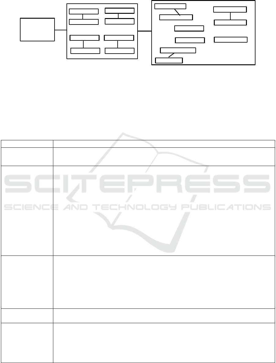
A general schema of the approach is represented on
the Figure 1.
The text to model transformation operation is
performed by the following steps:
1. An XMI representation of a SM is parsed.
Recognized SM elements and links between them
are stored in the memory (Figure 1, Link 1).
2. Then chains from linked SM elements are
formed. Every chain stores information about a part
of an algorithm or a business process, represented in
a behavioral SM (Figure 1, Link 2).
In order to perform the transformation from text
to model the next Research Problems (RPs) should
be solved:
RP1: to investigate regularities of the SM
elements stored in an XMI file.
RP2: to propose an algorithm for defining linked
SM elements in the XMI file for different types of
UML diagrams.
RP3: to design an analytical foundation for SM
representation and forming of linked chains.
RP4: to introduce a concept of behavioral SM
decomposition into chains of linked elements with
further restoring of its structure.
RP 4.1: to introduce a concept of composing
chains of linked elements for behavioral SM;
An Approach of Text to Model Transformation of Software Models
433
UML
diagram
XMI file
….
….
….
Element 1
Element 2
Element m
Element n
Element 1
Element 3
Element n-1
Element n
…
.
Element 1
Element 2
Element 1
Element 3
Element m
…
.
Element m
Element m
Element m+1
Element n
….
1 2
Figure 1: Approach for restoring a software model structure from an XMI file.
RP 4.2: to explain an idea how to restore
structure of behavioral SM from these chains.
Solutions of RPs:
The solutions of RP1 and RP2 are proposed in the
paper (Chebanyuk and Mironov, 2017).
Solution of RP3: It is proposed to use graph
representation to describe SM analytically.
Analytical foundations of SMs representation for
forming linked chains is represented in the Table 1.
Table 1: Analytical denotations for restoring software model structure.
Concept
Explanation and analytical representation of concept
Software model
According to the UML 2.5 standard SM is an UML diagram.
Denote it as SM and SM of
some type as
type
SM
where type=use case, type=class, etc.
Software model
representation
The graph representation is chosen.
),(
typetypetype
LOSM
(1)
where
type
O
– a set of SM objects that are used in
type
SM
notation.
.
Objects are the
elements of SM notations that can be expressed as graph vertexes.
type
L
– a set of software model links that are used in
type
SM
notation. Links are
elements of SM notation that can be expressed as graph edges.
Common definitions for behavioral SM representation are presented in the paper
(Chebanyuk, 2015)
Elementary sub-
graph
It is a part of a graph, consisting of two linked vertexes.
Denote an elementary sub-graph as:
),,(
21
oloe
(2)
where
Ooo
21
,
are software model objects linked by link
Ll
.
Set of elementary
sub-graphs
All elementary sub-graphs of SM. Denote this set as A.
Linked Elementary
Sub-Graphs (LESG)
Consider two elementary sub-graphs
),,(
2111
oloe
and
),,(
3222
oloe
If two elementary sub-graphs are interconnected through an object
Oo
2
these two sub-
graphs are considered linked. Consider a pair of elementary sub-graphs
1
e
and
2
e
Determine
1
e
as the first linked elementary sub-graph,
2
e
respectively as the seconds.
ENASE 2018 - 13th International Conference on Evaluation of Novel Approaches to Software Engineering
434

Concept
Explanation and analytical representation of concept
Starting border
elementary sub-
graph
Elementary sub-graph that has no first linked elementary sub-graph. Consider
),,(
2111
oloe
.
Usually
Oo
1
is an object from which streams of UML diagram are
stated. These objects are actors or objects that have no incoming links.
A set of starting
border elementary
sub-graphs
A set that contains all starting border elementary sub-graphs of software model.
Denote this set as START.
||},,...,,{
,2,1,
STARTkeeeSTART
kstartstartstart
(3)
Switching
elementary sub-
graphs
Consider two linked elementary sub-graphs.
),,(
2111
oloe
and
),,(
3212
oloe
.
They are
started
from the
Oo
1
. An elementary graph located on SM before
),,(,
100021
oloeeande
is determined as a switching elementary sub-graph.
A set of switching
border elementary
sub-graphs
A set that contains all switching elementary sub-graphs of a SM. Denote this set as
SWITCH.
||},,...,,{
,2,1,
SWITCHpeeeSWITCH
pswitchswitchswitch
(4)
Finishing border
elementary sub-
graphs
An elementary sub-graph that has no the second linked elementary sub-graph. Consider
),,(
2111
oloe
.
Usually
Oo
2
is an object to which streams of UML diagram are
ended. Other words these objects have no outcoming links.
A set of finishing
border elementary
sub-graphs
A set that contains all finishing border elementary sub-graphs of a SM.
Denote this set as FINISH.
||},,...,,{
,2,1,
FINISHteeeFINISH
tfinishfinishfinish
(5)
A set MIDDLE
All elementary sub-graphs that are not included to sets START, SWITCH, and FINISH are
included to the MIDDLE
Software model
sub-path
A part of software model, consisting from chain of linked elementary sub-graphs. Denote
a sub-path of a SM as chain. Using (2) chain is denoted by the following:
1 1 2 2 2 3 1 1
12
(( , , ),( , , ),...,( , , )), | |
( , ,..., )
n n n
n
chain o l o o l o o l o n chain
chain e e e
(6)
where n is a number of elementary sub-graphs in sub-path.
There are several variants of forming chains
beginning from a border elementary sub-graph and ending on a switching
elementary sub-graph;
beginning from a next elementary sub-graph to switching one (the second
elementary sub-graph in pair of linked elementary sub-graph ) and ending on other
switching elementary sub-graph;
beginning from a next elementary sub-graph to switching one (the second
elementary sub-graph in pair of linked elementary sub-graph ) and ending on the
finishing border elementary sub-graph;
beginning from a starting border elementary sub-graph and ending on finishing
border elementary sub-graph.
Set of software
model sub-paths
All SM chains that contain all its objects and links.
||},,...,,{
21,
PATHnchainchainchainPATH
n
(7)
An Approach of Text to Model Transformation of Software Models
435

Solution of RP4: to solve RP4 is it is necessary
to design a process of behavioral SM decomposition
into chains of linked elements with further restoring
of its structure.
Rules of Processing a Set A of SM:
The formal rules for analyzing the SM
elementary sub-graphs allow classifying them to
START, SWITCH, FINISH, and MIDDLE sets.
The rules are:
− a rule for including of an elementary sub-
graph to a set START;
− a rule for including of an elementary sub-
graph to a set SWITCH;
− a rule for including of an elementary sub-
graph to a set FINISH;
− a rule for including an elementary sub-graph
in to a set MIDDLE.
A Rule for Including an Elementary Sub-
graph in the Set START:
Consider a reference elementary sub-graph
( , , )ref subj l obj
.
A Condition for Proving that RefϵSTART: If
there is no possibility to design a LESG with any
1 1 2
, ( , , )A el l el
with the common
element
2
el
namely:
1 1 2
( , ) (( , , ),( , , ))LESG a ref el l el subj l obj
than the ref is included to the set START. Formally
this rule is expressed by the next predicate:
2
1 1 2
( , , ) ( ) ,
( , , ),
P subj A A el subj false
el l el A
(8)
The expression (8) should be true for all
A
.
Formally, the representation of the condition proving
that ref ϵ START:
( , )if P subj A false then ref isadded
totheset START
Rule for Including an Elementary Sub-graph in
the Set SWITCH:
Consider an elementary sub-graph ref. If there is
a possibility to design more than one LESG with any
1 1 2
, ( , , )A el l el
with the common
element obj, namely:
1 1 2
( , ) (( , , ),( , , ))LESG ref a subj l obj el l el
than ref is included to the set SWITCH. It is formally
expressed by the next predicate:
1,
1 1 2
( , , )
( | 2) ,
( , , ),
i
i
P obj A
A el obj i true
el l el A
(9)
The next step is to form the set SWITCH from all
ϵA for which
( , , )P obj A true
. It is expressed
by the next predicate:
{ | ( , , ) }W A P obj A true
The next step is to define a number of elements
in the set W.
| | 1if W thenref isaddedtoSWITCH
Rule for Including an Elementary Sub-graph
in the Set FINISH:
A condition for proving that refϵFINISH: If there is
no possibility to design a LESG with any
1 1 2
, ( , , )A el l el
with the common
element
2
el
, namely:
1 1 2
( , ) (( , , ),( , , ))LESG ref a subj l obj el l el
than the ref is included to the set FINISH. It is
formally expressed by the next predicate:
1
1 1 2
( , , ) ( ) ,
( , , ),
P obj A A el obj false
el l el A
(10)
The expression (10) should be true for all
A
.
Formally representation of the Condition for
proving that ref ϵ FINISH:
( , , )if P obj A false then ref
isadded totheset FINISH
Rule for Including an Elementary Sub-graph
in Set MIDDLE:
All elementary sub-graphs of a SM that do not
satisfy the rules represented above are added to the
set MIDDLE
The process of forming the set CHAIN by
analyzing software model is described below:
1. An XMI representation of an UML diagram
is read. The set A which contains all SM
objects and links is formed.
2. The set START from the set A is formed
performing the following operations:
2.1 The counter k increments from 1 to |A|.
The start value of the counter is k=1.
2.2 Assume that
k
start ref
.
ENASE 2018 - 13th International Conference on Evaluation of Novel Approaches to Software Engineering
436

2.3 Choose ϵA. Consider =ref and verify
whether ref corresponds to the set START
according to the rule proposed above (8).
If yes, add ref to the set START and delete
ref from the set A.
2.4 Increment the counter k. If k<|A| go to the
point 2.2 otherwise go to the point 3.
3. The set SWITCH is formed performing the
similar actions described in the point 2.
4. The set FINISH is formed performing the
similar actions described in the point 2.
5. All ϵA that are left in the set A are copied
to the set MIDDLE.
6. Prove that the set
START
. Otherwise
the SM was recognized with an error and its
further processing is impossible.
7. To set the counter of the linked chain i=1.
8. Assign
1
ref start
. Then remove the
1
start
from the set START and add it to the
i
chain
9. Consider sequentially all elementary sub-
graphs from the set SWITCH with the aim to
design LESG. If it is possible then
9.1. the founded
switch SWITCH
is added
to
i
chain
and removed from SWITCH;
9.2. the forming of
i
chain
is finished;
9.3. the counter i is incremented by one;
9.4. If
START
then go to the point 8;
9.5. else if
SWITCH
assign the
ref=switch
1
and delete the switch
1
from
the SWITCH and add it to
i
chain
and go
to the point 10
9.6. if
SWITCH
the processing of the
SM is finished.
10. Consider sequentially all elementary sub-
graphs from the set FINISH with the aim to
design the LESG. If it is possible then:
10.1.
finish FINISH
is added to
i
chain
and removed from FINISH;
10.2. Forming of
i
chain
is finished;
10.3. Counter i is incremented by one;
10.4. if
START
then go to the point 8
10.5. if
SWITCH
assign ref=switch
1
and delete from the SWITCH and add it to
i
chain
and go to the point 10
11. Consider sequentially all elementary sub-
graphs from the set MIDDLE with the aim to
design LESG If It is possible then:
11.1.
MIDDLE
is added to the
i
chain
and removed from the set MIDDLE;
11.2. if
SWITCH
go to the point 9
11.3. if
FINISH
go to the point 10
11.4. if
MIDDLE
go to the point 11
11.5. if
MIDDLE
then forming of
analytical representation of the SM is
finished.
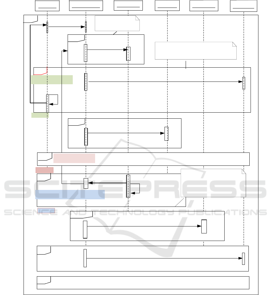
Sequence diagram of forming linked chains
from XMI representation of UML diagram is
represented in the figure 2 (on the next page).
12. The next step is to compose a set PATH . To
define continuation of path for
i
chain
it is
necessary to compare the last elementary sub-
graph with the first elementary sub-graph for
all other
chain CHAIN
4 CONCLUSIONS
This paper proposes the text to model transformation
approach. The input data are taken from a SM stored
in an XMI format. As a result of transformation, a
set of linked chains from elementary sub-graphs is
obtained. These chains are combined into paths that
repeat the SM structure. Many techniques,
approaches, and software tools can obtain
information about SMs. Advantage of the proposed
approach is the possibility to process both behavioral
and static SMs obtaining information about their
structure in details.
Model transformation tools allow obtaining new
software models from existing ones. For example
Medini QVT is a convenient tool for round trip
engineering (Greiner at al, 2016), but there are
limited possibilities to compose transformation rules
using elements that are not linked directly In this
case it is difficult to compose transformation rules
to perform “many-to-many” and “many-to-one”
transformations.
The executable UML tools as MOKA and IBM
Rational Software Architect (RSA) simulation
toolkit allow simulating of SMs execution.
An Approach of Text to Model Transformation of Software Models
437
Ref block
loop
loop
2. Search LESG
1. select
MIDDLE
else
[LESG is formed]
3. Copy to chain(i)
alt
loop
6. Search LESG
FINISH
[j=1,j<|SWITCH|]
4 has elements
[j=1,j<|FINISH|]
START
reference
SWITCH
9. select
5. i++
10. i++
chain(i)
[Yes?]
[Yes?]
Copy to reference to chain
assign reference=start(1)
Copy to reference to chain and assign reference=start(1)
ref
8 has elements
alt
[LESG is formed]
[set SWITCH is not empty]
loop
11. Search LESG
else
[LESG is formed]
12. Copy to chain(i)
if SWITCH is
not empty
assign ref=switch1
[j=1,j<|MIDDLE|]
alt
if SWITCH is not empty assign ref=switch1 and goto “loop switch” block
ref
loop switch
else
Figure 2. Sequence diagram of process linked chains form XMI representation of software mode.
During the simulation, all steps of the business
process execution are performed sequentially.
Involving proposed approach it is possible to
simulate parallel processes. (Bedini at. al., 2017).
Proposed approach allows obtaining analytical
representation of the SM, repeating all details of its
structure. The linked chains of elementary sub-
graphs are combined into paths. The analysis of
these paths allows easily getting access to every
SM elementary sub-graph or group of them. Such a
scheme of a SM storing provides a possibility to
improve any other technique or software tools for
SMs processing.
ENASE 2018 - 13th International Conference on Evaluation of Novel Approaches to Software Engineering
438

5 FURTHER WORK
The continuation of the research represented in this
paper is to design comparison techniques to
compare linked chains of elementary sub-graphs.
It is planned to extend the analytical foundation
proposed the Table 1 and design software tools to
consider semantic aspects of SMs comparison. The
next step is to design a model versioning technique
for reflecting the refinement history.
REFERENCES
ASTM™, 2011 Architecture-Driven Modernization™
(ADM™): Abstract Syntax Tree Metamodel™
(ASTM™) http://www.omg.org/spec/ASTM/1.0.
Bedini F., Maschotta R., Wichmann A., Jäger S. and
Zimmermann A. (2017). A Model-Driven fUML
Execution Engine for C++.In Proceedings of the 5th
International Conference on Model-Driven
Engineering and Software Development - Volume 1:
MODELSWARD, ISBN 978-989-758-210-3, pages
443-450. DOI: 10.5220/0006206904430450.
Chebanyuk E. An approach to behavioral software
models analytical representation. International
journal Informational models and analysis.
– 2015, №1 P 61-79.
http://www.foibg.com/ijima/vol03/ijima03-02-p05.pdf.
Chebanyuk E. and Markov K. An Approach to Class
Diagrams Verification According to SOLID Design
Principles. In Proceedings of the 4th International
Conference on Model-Driven Engineering and
Software Development - Volume 1:
MODELSWARD (2016), ISBN 978-989-758-168-7,
pages 435-441. DOI: 10.5220/0005830104350441
access mode.
Chebanyuk E and Mironov Yu. An approach of
obtaining initial information for software models
analysis. “International journal. Informational
content and processing.”, Vol. 4, number 2 – 2017,
in press.
Chebanyuk E and Povalyaev D. An approach for
architectural solutions estimation “International
journal Informational theories and knowledge”, Vol
11, number 2– 2017, in press.
IBM, 2015 Rational Software Architect. Quick Start
Tutorial. https://www.fi.upm.es/catedra-
ibmrational/sites/www.fi.upm.es.catedra-
ibmrational/files/RSA_Tutorial.pdf.
Greiner S., Buchmann T. and Westfechtel B.
(2016). Bidirectional Transformations with QVT-R:
A Case Study in Round-trip Engineering UML Class
Models and Java Source Code.In Proceedings of the
4th International Conference on Model-Driven
Engineering and Software Development - Volume 1:
MODELSWARD, ISBN 978-989-758-168-7, pages
15-27. DOI: 10.5220/0005644700150027.
http://www.scitepress.org/PublicationsDetail.aspx?ID=ef
ZXth7Zbbg=&t=1.
ICER, 2015, Robinson, A., and Bates, C. Western
Michigan University project.
https://www.cs.wmich.edu/~OODA/patterns/AbsFactory
.html.
OCL, 2014 Object Constraint Language Version 2.4
OMG standard
http://www.omg.org/spec/OCL/2.4/PDF.
Papyrus, (2012) Papyrus, 2012. www.papyrusuml.org.
Unified Modeling Language (UML), 2012.
Ran Wei , Dimitrios S. Kolovos , Antonio Garcia-
Dominguez (2016) Towards Partial Loading of XMI
Models.. _c 2016 ACM. ISBN 978-1-4503-2138-9.
DOI: 10.1145/1235.
http://publications.aston.ac.uk/30611/1/Partial_loading_
of_XMI_models.pdf.
XMI, 2015 XML Metadata Interchange
http:// www.omg.org/spec/XMI/2.5.1/
Yuan Wang, David J. DeWitt, Jin-Yi Cai. X-Diff: An
Effective Change Detection Algorithm for XML
Documents. In: Proceedings 19th International
Conference on Data Engineering, Bangalore, India,
India 5-8 March, 2003 Page(s):519 - 530
http://pages.cs.wisc.edu/~yuanwang/papers/xdiff.pdf
DOI 10.1109/ICDE.2003.126081.
An Approach of Text to Model Transformation of Software Models
439
