
Simplified Definition of Parameter Spaces of a Procedural Model using
Sketch-based Interaction
Johannes Merz
1
, Roman Getto
1
, Arjan Kuijper
2,3
and Dieter W. Fellner
1,3
1
GRIS, TU Darmstadt, Fraunhoferstrasse 5, Darmstadt 64283, Germany
2
MAVC, TU Darmstadt, Fraunhoferstrasse 5, Darmstadt 64283, Germany
3
Fraunhofer IGD, Fraunhoferstrasse 5, Darmstadt 64283, Germany
Keywords:
Sketch based Modeling, Sketching, 3D Modeling, Parameter Ranges, Parametric Modeling, Procedural
Modeling.
Abstract:
This paper presents a novel technique to intuitively insert meta-parameters into a procedural model with the
help of sketch-based interaction. The procedural model is represented in a GML (Generative Modeling Lan-
guage) representation, which is a script language that focuses on the description of three-dimensional models.
A GML model consists of a sequence of procedural modeling commands, for example extrusions. These are
called with a set of local offset positions, which can be converted to global space and anchored in the surface
mesh by finding reference vertices on the mesh. The system uses a deformation technique to deform the sur-
face of the model. During the deformation, the reference vertices provide the global offset positions, whose
path can be approximated by a B-spline. Exchanging the initial values of the commands by this B-spline,
defines a continuous parameter space of the meta-parameter. The deformation process is supported by a mesh
segmentation to create pre-defined deformation targets. Using sketch-based methods, these can be adapted
to the user’s needs. The results show that the system closely imitates the deformation with the help of the
modeling commands. Furthermore, the system was evaluated to be intuitive and easy to use.
1 INTRODUCTION
In the context of computer graphics, the process of
creating a model that represents all instances of an
object is of major interest. Especially since the emer-
gence of computer-aided design (CAD), efforts have
been made to find representations of models that in-
corporate more information. Even with sophisticated
modeling software, the development of a large model
is a tedious process, thus the ability to reuse a varia-
tion of a preexisting model is of high importance.
By creating a model in a procedural way, it is pos-
sible to describe its variations. In a procedural model,
a sequence of modeling commands is executed, each
with a specific set of input parameters. Through the
definition of their parameter spaces, possible varia-
tions of the object (an object class) can be modeled
(Getto et al., 2017). However, the amount of parame-
ters in a procedural model poses a significant obstacle
during the parameter space definition.
To simplify this process, we propose a novel tech-
nique to specify the parameter spaces using sketch-
based interaction and a physically plausible deforma-
tion technique. Our system is based on the models
created using the sketch-based modeling tool from
(Bein et al., 2009) with the extension to extract pro-
cedural models described in (Getto et al., 2017).
The system functions by allowing the user to in-
tuitively deform the mesh that is created by the pro-
cedural model. Each parameter of the single proce-
dures (e.g. drag or extrude) represents an offset of the
control mesh that can also be interpreted as a global
position in the world space. These positions can be
anchored in the mesh by shooting rays to find refer-
ence vertices on the mesh surface. The global posi-
tions of the parameter offsets are now available us-
ing the barycentric coordinate on the line between the
reference vertices. By evaluating the position during
the deformation, B-splines for every parameter can be
deduced that mathematically describe the parameter
space controlled by a meta-parameter.
The goal is to provide an easy to use system,
which is why the deformation is supported by an ini-
tial mesh segmentation, proposing a number of de-
formation handles to the user. These can further be
refined with sketch-based interactions. Depending on
the refinement of the segmentation, the deformation
has global or local effect.
Merz, J., Getto, R., Kuijper, A. and Fellner, D.
Simplified Definition of Parameter Spaces of a Procedural Model using Sketch-based Interaction.
DOI: 10.5220/0006613002230231
In Proceedings of the 13th Inter national Joint Conference on Computer Vision, Imaging and Computer Graphics Theory and Applications (VISIGRAPP 2018) - Volume 1: GRAPP, pages
223-231
ISBN: 978-989-758-287-5
Copyright © 2018 by SCITEPRESS – Science and Technology Publications, Lda. All rights reserved
223
Our contribution is composed of the technique to
deduce the defined variations of the model’s parame-
ters and represent them using B-Splines. The user can
specify the variations by deforming individual seg-
ments of the model. Please note that the modeling
tool is not part of the contribution.
2 RELATED WORK
The definition of a procedural model is achieved by
writing out a sequence of operations. (Lindenmayer,
1968) defined the L-systems (Lindenmayer, 1968),
which have been repeatedly utilized to define para-
metric models (Herman et al., 1975; Tobler et al.,
2002) or combined with shape grammars (Parish and
M
¨
uller, 2001). Although powerful, the systems are
highly specialized, as they need a rule set to guide the
construction process and are thus not suitable for the
modeling and parameterization of arbitrary shapes.
Alternatively, (Wyvill et al., 1999) combined
CSG-Trees with skeletal implicit primitives as leaf
nodes in their BlobTrees. By combining the field
functions, they can be easily blended (Bernhardt et al.,
2010) and the tree elements allow for interactive edit-
ing, swapping or removal.
Moreover, with languages such as the stack-based
Generative Modeling Language (GML) (Havemann,
2005; Havemann and Fellner, 2003), modeling oper-
ations can simply be built on top of each other. These
complex operation are controlled by a small set of pa-
rameters. Using a postfix notation similar to Adobe
PostScript and euler operations based on a half-edge
data structure, a control mesh can be created. This
will be evaluated using a modified Catmull/Clark sub-
division scheme that allows for sharp edges.
Generally, sketch-based modeling systems can be
classified into two categories, construction based and
recognition based systems (Kazmi et al., 2014). The
latter use sketches as shape descriptors and retrieve
models from shape databases (e.g. (Eitz et al., 2010;
Eitz et al., 2012)), which needs prior-knowledge and
hence is opposed to our goal to initially define an ob-
ject class. Thus, we focus on the former category.
Pioneering systems in modern sketch-based mod-
eling inflate two-dimensional sketches of silhou-
ettes to three-dimensional models and allow further
refinement with sketch-based modeling operations
(Igarashi et al., 1999; Nealen et al., 2007). However,
they lack possibilities to parameterize the model and
thus are not a good base for our system.
The more complex ShapeShop system (Schmidt
et al., 2005) is based on BlobTrees and functions by
creating and adapting a 2D template scalar field, fit-
ting the implicit surface to the user’s sketch. The hi-
erarchical tree structure provides a number of manip-
ulation possibilities for a meta-parameter, similar to
(Schmidt and Singh, 2008) which adds layer based
editing. However, the interaction with a hierarchi-
cal tree-view widget has been evaluated as unintuitive
and difficult for designers (Jorge and Samavati, 2011).
(Bein et al., 2009) developed a sketch-based mod-
eling tool based on GML. The initial sketch is con-
verted into a control polygon using a B-spline approx-
imation scheme and then extruded. Modeling com-
mands such as the SketchExtrude operator (Figure
1(a)) or the RotationExtrude (Figure 1(b)) are pro-
vided. Along a sketch, the base face on the control
mesh is copied and rotated (SketchExtrude) or scaled
(RotationExtrude) along the path. Yet, the insertion
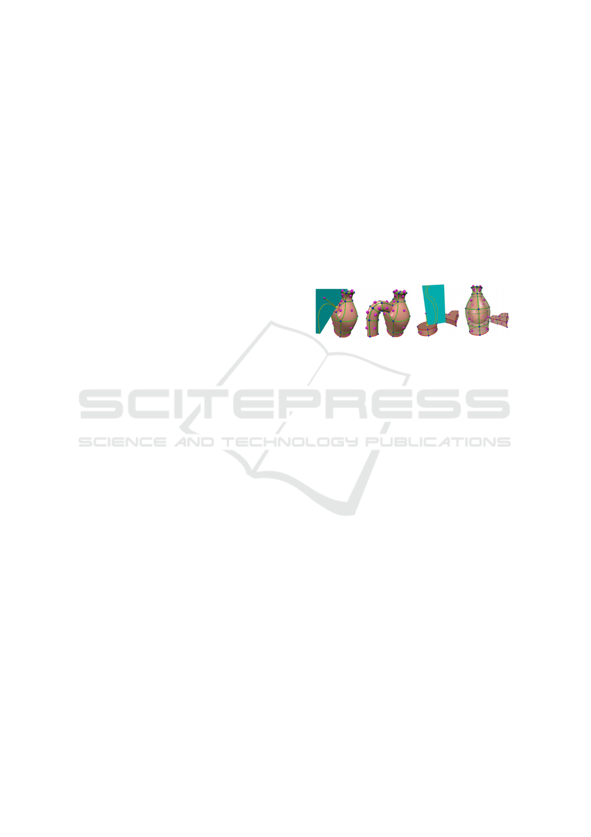
(a) (b)
Figure 1: The SketchExtrude operator extrudes the control
mesh along a sketch path (a). In (b) a sketch is used to
define the scale of the extrude along the surface normal for
a RotationExtrude. Taken from (Bein et al., 2009).
of parameters is not possible, because the tool only
exports the tessellation of the surface.
(Getto et al., 2017) extended the tool to record the
construction as GML code that can be exported to a
script file, which iteratively calls the modeling func-
tions with a fixed set of parameters. Moreover, a set
of rules for the insertion of meta-parameters were de-
fined, which in turn adapt the command parameters.
Although supported by a simple user interface, it is
complicated and requires a high level of knowledge
about the effects of each parameter. Simplifying this
step is the goal of our technique, justifying the deci-
sion to use this system as a base.
Using a deformation as a target state stems from
sketch-based animation. (Bessmeltsev et al., 2016)
used sketched silhouettes as targets to pose an exist-
ing character model. In (Choi et al., 2016), sketched
curves on joints serve as guides for the animation
of characters, which inspired our use of B-splines to
guide the variations.
The goal of creating a meta-representation of an
object is comparable to (Fish et al., 2014; Kim et al.,
2013). The difference however is that we define a
shape familiy (object class) on a single instance in-
stead of learning it from a larger set of representatives.
GRAPP 2018 - International Conference on Computer Graphics Theory and Applications
224
3 PRELIMINARIES AND USER
INTERACTION
3.1 Sketch Projection
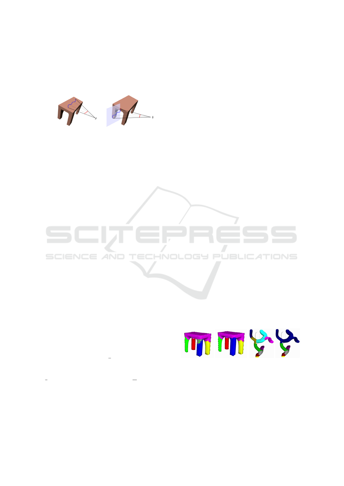
(a) (b)
Figure 2: The red line was sketched and is projected directly
onto the model (a) or onto a minimum-skew viewplane (b).
The system is controlled by sketch-based user input.
Usually the user has a specific kind of projection into
the 3D-space in mind and the correct implementation
is up to the system. Our system uses two different
strategies. The user can refine an automatic segmen-
tation with sketches (Section 3.3). In this case the
sketches are perspectively projected onto the model
(Figure 2(a)). However, while performing a deforma-
tion, the system needs to anticipate a projection plane.
To achieve this, we use the minimal-skew viewplane
projection proposed in (De Paoli and Singh, 2015).
To deform the mesh along a sketch, the user naturally
needs to start the sketch on the model. Thus, we can
calculate the minimum-skew viewplane (Figure 2(b))
using the surface normal at the first hit point.
3.2 Mesh Refinement
After the interpretation of the script, the control mesh
is subdivided to extract the limit surface. The sub-
division algorithm creates a detailed tessellation in
smooth areas of the object. Sharp areas are coarsely
triangulated, creating areas with high anisotropy. A
refinement ensures enough degrees of freedom to sup-
port small dislocations of vertices during the deforma-
tion. Because the model was previously sketched by
free-handed, most triangles are smooth. We use the
algorithm by (Botsch and Kobbelt, 2004), since it al-
lows us to provide a set of triangles that need to be
refined as well as a target edge length.
The median edge length e is a good target for the
anisotropic triangles. To select these triangles, we cal-
culate the interquartile range (IQR) between the lower
(
n
4
th element) and the upper quartile (
3n
4
th element).
Finally, the following heuristic is applied:
D
out
:= {D | D > Q
3
+ 1.5 · IQR}. (1)
This is a common technique to detect outliers in the
explorative data analysis (Pagano, 2013).
For Section 4.1 we need to preserve correspon-
dences between the unrefined and refined mesh,
which is easily done by finding the closest vertex on
the refined mesh for every unrefined vertex.
3.3 Mesh Segmentation
When using deformation algorithms, three sets of
points need to be defined. Handle points are directly
deformed by the user, fixed points on the other hand
cannot move. The leftover points are free to move,
mostly according to a specified energy function.
Having the user directly specify the fixed points
in advance of each deformation would require great
effort. He would have to anticipate the effects of the
deformation and constrain it manually to produce the
desired response. To simplify this process, we de-
duce the fixed points by preparing a mesh segmen-
tation. Our system uses the algorithm by (Shapira
et al., 2008), because it is invariant to pose changes
and the optimal number of segments is automatically
chosen. When the user starts the deformation process,
all vertices outside the relevant segment are fixed. We
preadjusted the algorithm to provide a liberal segmen-
tation, hiding the parameters of the algorithm from
the user, yet it might lead to more segments than the
user needs. Thus, two simple sketch-based tools are
introduced to refine the segmentation.
First, the user can extrude a single segment. A
sketch needs to be started on the segment that is
extruded and dragged over neighboring segments to
overwrite the segment membership in a local region
around the sketch. Figure 3(a) shows an example.
Second, if the user wants the deformation to affect
more parts of the model, multiple distinct segments
can be merged. This is achieved using another refine-
ment tool, which must also be started on the segment
that should be inherited by others. A sketch collects
all crossed segments by projecting the points onto the
model and merges them to one, as seen in Figure 3(b).
(a) (b)
Figure 3: In (a) the blue segment is extruded along a sketch
and in (b) several segments are merged with the red sketch.
3.4 Mesh Deformation
After the input model has been refined and seg-
mented, the user can start creating parameters. This
Simplified Definition of Parameter Spaces of a Procedural Model using Sketch-based Interaction
225
is achieved by deforming the mesh. To achieve phys-
ically plausible deformation, we chose the as-rigid-
as-possible deformation technique by (Sorkine and
Alexa, 2007). During the deformation, the system
saves one deformed intermediate mesh per sketch
point. These are needed at a later stage of the pa-
rameter insertion. Our system supports three differ-
ent kinds of deformations. First, by picking and drag-
ging a point on the mesh along a sketch path, the han-
dle points can be defined as the three vertices of the
selected triangle. The fixed points are then chosen
as all points outside the selected segment. However,
this behavior might not be what the user intended to
achieve. In the example in Figure 4(a), the intention
was to change the length of the seating surface of a
simple chair. Obviously, the result is far from correct,
the front of the green segment would have to move
uniformly together with the yellow and the pink seg-
ments. To overcome this, the system offers a second
deformation handle. By choosing a segment-spanning
face deformation, the handle points are spread out un-
til a discontinuity in the face is detected. Moreover,
the system temporarily merges all three segments for
one deformation, creating a region of interest. The
set of fixed points now only consists of all points that
do not lie in the region of interest. Figure 4(b) shows
the result of the same deformation with the alterna-
tive deformation handle. A third handle definition, the
segment-bounded face handle, can also be utilized. It
differs from the previous one, because it remains con-
strained by the original segment.
(a) (b)
Figure 4: Deformation of the chair’s seating surface with
the standard deformation handle (a) and the segment-
spanning handle (b).
4 PARAMETER INSERTION
TECHNIQUE
After the deformation process, the system needs to de-
termine the mathematical definitions of the intended
meta-parameter. By varying this meta-parameter in
the interval [0, 1], the procedural model interpolates
the deformation process as closely as possible.
4.1 Command Analysis
A two-stage process decides, which commands of the
script are relevant. By analyzing the deformed mesh,
a set of displaced points V is formed. The derived
set is then checked against each step of the proce-
dural model’s construction process. To improve the
runtime, not all vertices of the deformed segment are
included in the set V :
1. The deformation process works on the refined
mesh with a much larger number of vertices than
the original mesh. Only working on the vertices
on the refined mesh, that correspond to a vertex
on the unrefined mesh, reduces the size. The cor-
respondence is described in Section 3.2.
2. Furthermore, all vertices outside the region of in-
terest (ROI) can be excluded from the set. This
set of segments contains the vertices that are not
fixed. Thus, they are the only ones that could pos-
sibly be moved by the deformation.
3. For vertices in a small local region, the displace-
ment distances usually are almost identical. Thus,
all vertices with similar movement can be omitted.
Also, experiments revealed that it is sufficient to
only use the top 20% of the remaining vertices,
as these represent the characteristic movements of
the deformation.
After having specified the set of characteristic de-
formation vertices V , they can be used to identify the
commands that must be parameterized. Conceptually,
this is done by executing the GML script one com-
mand at a time (Algorithm 1). In each step, the sur-
face of the constructed model is checked against V . If
any point is directly on the surface of the model, the
last executed command must be parameterized. For
this purpose, the algorithm iterates over each control
face. If it contains smooth edges, it has to be subdi-
vided before the testing. Afterwards all detected ver-
tices are removed from the set, because they would
be false-positive results in every subsequent step. The
algorithm terminates, when the set V is empty or all
commands have been executed.
An additional function (Line 8) checks, whether
the currently executed command is a construction
command. In total, the sketch-based modeling tool
supports 17 modeling commands, however not all
of them are needed to adapt the model to the de-
formation, as some commands e.g. only change
the sharpness of a control point. We identified
the following six modeling commands as relevant:
NewObject, SketchExtrude, RotationExtrude, Drag-
Face, DragEdge, DragVertex.
For example, each picture in Figure 5 results by
GRAPP 2018 - International Conference on Computer Graphics Theory and Applications
226
Algorithm 1: Identify Commands.
1: function IDENTIFYCOMMANDS(V )
2: I D :=
/
0
3: for i = 0 to C .size() do
4: if V =
/
0 then
5: exit
6: end if
7: EXECUTE(C [i])
8: if ISCONSTRUCTIONCOMMAND(C [i])
∧ POINTONMODEL(V ) then
9: I D.insert(i)
10: end if
11: end for
12: return I D
13: end function
14:
15: function POINTONMODEL(V )
16: pointOnModel ← False
17: for all f ∈ F do
18: if f is smooth then
19: patch ← SUBDIVIDE( f )
20: else
21: patch ← f
22: end if
23: for all v ∈ V do
24: if DISTANCE(v, patch) < ε then
25: pointOnModel ← True
26: V .remove(v)
27: end if
28: end for
29: end for
30: return pointOnModel
31: end function
(a) (b) (c) (d)
Figure 5: The iterative construction process of the procedu-
ral model after command 1 (a), 2 (b), 3 (c) and 7 (d).
executing subsequent construction commands. Ad-
ditionally, the characteristic deformation vertices are
shown in blue. After performing the first two com-
mands 5(a) and (b), none of the points are on the sur-
face of the created model. However, after the execu-
tion of 5(c), a subset of V (red) coincides with the
models limit surface. After several more commands,
the command executed in 5(d) detects all remaining
points in V , resulting in V =
/
0 and terminating the
algorithm. The result of Algorithm 1 for our example
is I D = {3, 7}.
4.2 Tracking the Offsets
During the deformation, the system stored intermedi-
ate steps for every sketch point. This is important, be-
cause a user sketch is not necessarily a straight line.
One thing that all the relevant modeling commands
have in common is that each builds on some form of
point position. These can be either in form of cylin-
drical coordinates with respect to the command’s base
face (SketchExtrude and drag commands), global
point positions (NewObject) or more abstract extrude
data (RotationExtrude). All of them can (if needed)
be converted to global points that lie either inside the
undeformed mesh or on its surface. Inversely, the
changed global offset positions can be monitored. If
the position is directly on the surface of the mesh, this
is especially simple. Otherwise, reference vertices
have to be chosen, so that the global offset position
lies on the line defined by these vertices. Then the
position is described by the barycentric coordinate on
that line. Depending on the command type, the refer-
ence vertices have to be chosen differently.
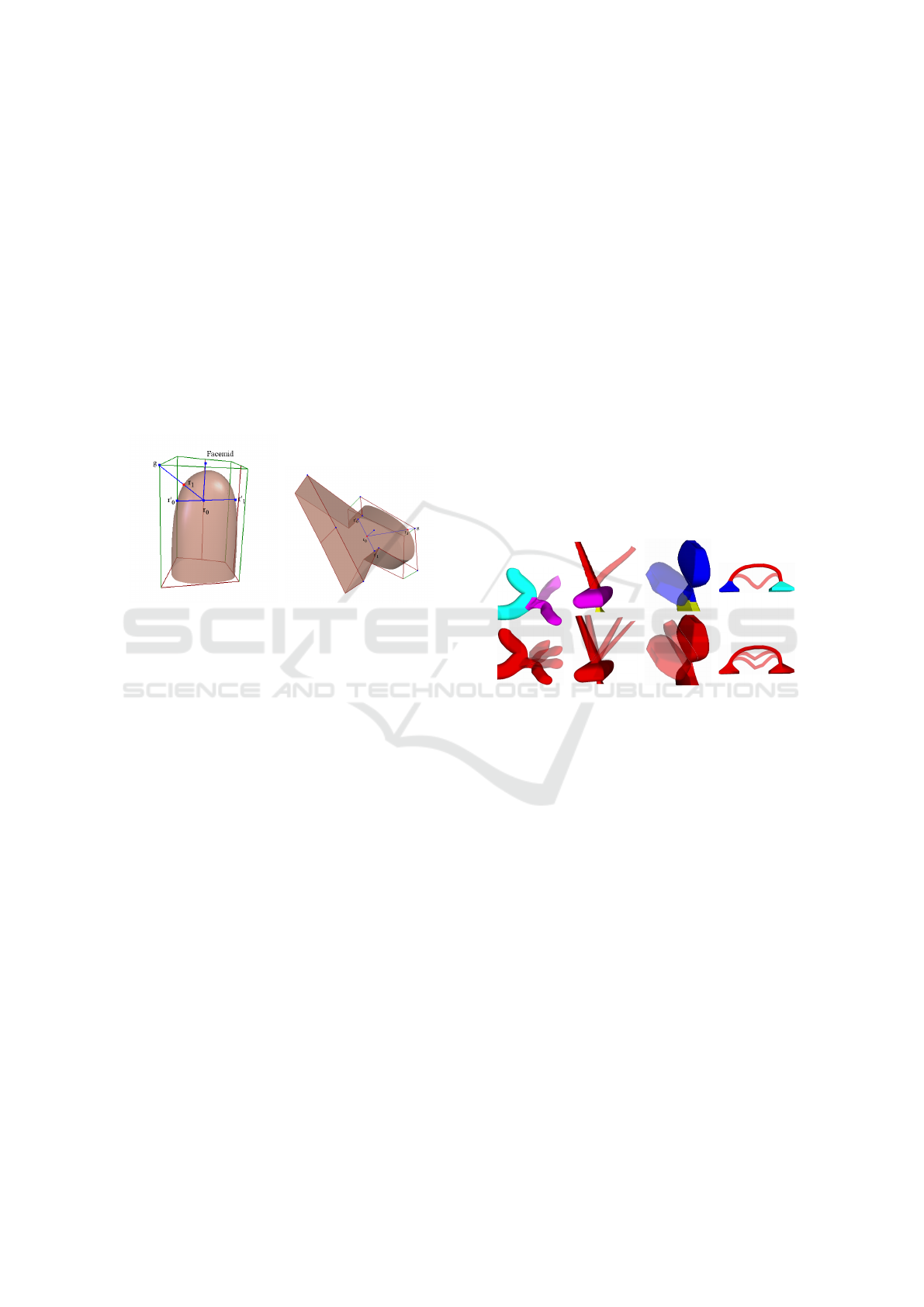
4.3 SketchExtrude
A SketchExtrude command has several parameters.
Figure 6(a) is a close-up view of the base face of a
sketch extrusion. What is already known to us are its
midpoint, its face normal n and an arbitrary orthogo-
nal vector o in the faces plane that defines φ = 0 of the
cylindrical coordinate system. Furthermore, we know
the offsets of each new face along the extrude path
as cylindrical coordinates with respect to the previous
face. By converting them into cartesian world coor-
dinates and iteratively adding them to the base faces
midpoint, we can calculate the global positions g
i
in-
side the deformable mesh: g
i
=
∑
i
j=0
l
j
.
(a) (b)
Figure 6: In (a) the structure of the first extrude of a
SketchExtrude is shown. (b) visualizes the reference lines.
To create a link between the surface mesh and the
point inside the model, we rotate the orthogonal vec-
tor o by the corresponding angle α of each extrude
step around the rotation axis ra. By shooting a ray
from g in the vectors direction and its opposite direc-
tion, two reference vertices on the model’s surface r
0
Simplified Definition of Parameter Spaces of a Procedural Model using Sketch-based Interaction
227

and r
1
are retrieved (Figure 6(b)). These vertices can
be tracked during the deformation of the mesh. By
calculating the barycentric coordinates λ of g on the
line r
0
r
1
before the deformation, the position of g can
be derived in any arbitrary deformation step:
λ
g
=
|r
1
− g|
|r
1
− r
0
|
, r
1
, r
2
∈ D
0
(2)
⇒ g
de f
= r
1
− λ
g
· (r
1
− r
0
) , r
1
, r
2
∈ D
i
. (3)
Figure 7(a) shows a deformation along the red
sketch. Using the precomputed barycentric coordi-
nate λ, the position of g in the deformed meshes
is evaluated. This yields a discrete set of deformed
global positions for each original g, which is approx-
imated by B-splines using the method presented in
(Bein et al., 2009) and is shown in Figure 7(b). Via in-
terpolation of the B-splines with a parameter t ∈ [0, 1],
an arbitrary deformation state can be recreated.
(a) (b) (c)
Figure 7: During the deformation intermediate steps are
saved (a). These are used to evaluate the global offset posi-
tions per step, which form B-splines (b). Figure (c) shows
the anchoring scheme at an end piece of a SketchExtrude.
If the SketchExtrude contains discontinuous parts,
it can happen that the reference line is of bad quality.
In this case, the reference line is much longer than
the other ones and the point g tends to be far from
the middle of the line. To resolve such an issue, the
reference line is rotated until it is of good quality. The
rotation axis is retrieved by rotating the base face’s
normal n similarly to the orthogonal vector.
So far, all global positions were located inside the
model. Yet, if the command was used to model an end
piece of the object, the last g is not necessarily inside
the model. Depending on the sharpness of the last
control face, it either lies on the surface or outside the
model. The global offset position g of the end piece
in Figure 7(c) lies outside the model, thus it cannot be
anchored in the mesh using the same concept. Alter-
natively, a ray is shot from the previous point inside
the model g
prev
in the direction of g. An intersection
with the models surface is detected, providing r
1
. Al-
though g
prev
is not a vertex of D
0
, we have already
anchored it in the mesh, thus it can be utilized as r
0
.
With both reference vertices, the position of g outside
the mesh can be evaluated. This time however, λ > 1
is used to extrapolate outside the bounds of the line
connecting r
0
and r
1
.
Now that the B-splines describing the offsets of
the SketchExtrude commands can be created, they are
inserted into the script. At the same time, a meta-
parameter p ∈ [0, 1] is added, which constitutes the
parameter p of the B-splines B(p). A value of p = 0
leaves the model as it was before, while p = 1 corre-
sponds to the fully deformed mesh. When rebuilding
the model, the evaluation of the B-Splines yields the
positions of the offset points g. Moreover, two steps
are needed in preparation of the command:
1. In case more than one parameter applies to the
same command, their influence is summed up and
the final cylindrical coordinates are calculated.
2. The local angles need to be reevaluated, since
they were only valid for the original undeformed
model. They are calculated using the evaluated
positions from the B-Splines. For each extruded
face, the rotation angle α
i
with respect to the com-
mands base face is the angle between the base
faces normal vector n
0
and the vector from the
previous point g
i−1
to the next g
i+1
. The rotation
axis ra is used as a constant rotation direction.
φ(u, v) := cos
−1
u · v
|u| · |v|
(4)
l
i
=
(
g
i+1
− g
i−1
, i ∈ {1, . . . , n − 1}
g
i+1
− g
i
, i = n
(5)
α
i
=
(
2π − φ(n
0
, l
i
) , ra ·(n
0
× l
i
) < 0
φ(n
0
, l
i
) , else.
(6)
4.4 DragFace, DragVertex, DragEdge &
NewObject
The DragFace command is similar to a SketchExtrude
that only performs a single extrude and thus functions
analogous to its end case (Figure 7(c)). However, we
have no previous position g
prev
to use as a reference
vertex. Because of this, we shoot a ray from g in the
opposite direction of the face normal into the model.
The intersection point is r
1
and by following the ray
a little further into the model we choose an arbitrary
point inside the mesh as r
0
. Since the second point
is again not fixed in the mesh, we use the same tech-
nique as in the general case of the SketchExtrude to
track its position, hence we have two more reference
vertices r
0
0
and r
0
1
to anchor r
0
.
GML uses a half-edge data structure, thus an edge
is always associated with one vertex. Due to this, the
DragVertex and DragEdge commands use the same
parameters. Instead of tracking a position in the mid-
dle of a dragged control face, we are interested in a
GRAPP 2018 - International Conference on Computer Graphics Theory and Applications
228
vertex of the face. However, the approach is similar:
From g, we shoot a ray back inside the mesh to find
r
0
which is anchored using a reference line in orthog-
onal direction (r
0
0
and r
0
1
). From r
0
another ray is shot
towards the vertex of the control face and the inter-
section with the mesh gives us r
1
(see Figure 8(a)).
The NewObject command has no offsets in cylin-
drical coordinates, but only control points of the ini-
tial sketch. These are combined to a face and extruded
by 0.5 units in the opposite direction of the face nor-
mal. Thus, we shoot a ray from the face midpoint
in the opposite direction of the face normal and stop
after 0.25 units to find a point in the middle of the
mesh r
0
. From there, we shoot rays towards the con-
trol points and use the intersections as r
1
(see Figure
8(b)).
(a) (b)
Figure 8: The anchoring schemes for a DragVertex /
DragEdge (a) and a NewObject command (b).
4.5 RotationExtrude
The RotationExtrude command is similar to the
SketchExtrude, as both can be used to construct new
geometry. While the latter employs the user sketch to
define the path of the extrude, the former has a fixed
direction. It always extrudes by l
i
along the normal
of the base face. As a consequence, the command-
parameters are suitable to elongate and scale the
structure. The sketch is used to define the scale s
i
of each new face, as compared to the base face. How-
ever, a user-guided deformation does not necessarily
follow these constraints, because a deformation often
bends a structure. Thus, the RotationExtrude com-
mand needs to be adapted in order for it to be able
to follow a deformation similarly to a SketchExtrude.
We calculate the positions g of the new extruded faces
on the face normal and apply the same technique as in
Section 4.3.
A SketchExtrude needs a rotation normal ra to
calculate the local angles, which is lacking in this
command. During the evaluation, ra is deduced, by
taking the cross product of the vector from the base
face g
0
to g
1
in the original state and the same vector
in an arbitrarily deformed step:
ra = (g
1,orig
− g
0,orig
) × (g
1,de f
− g
0,de f
). (7)
During the evaluation of the procedural model, the
calculated offsets are simply used to move the control
vertices.
5 RESULTS
We used several minimal procedural models to test
the parameterization of each modeling command sep-
arately. In Figures 9(a) - (c) a selection of them are
presented. Their successful processing demonstrates
that the single parts of the system work individually.
Furthermore, it is important that the parameteri-
zation of a command does not vary subsequent parts.
In the example in Figure 9(d) only the red segment
was deformed by the user and it can be seen that the
resulting variations comply to this constraint.
(a) (b) (c) (d)
Figure 9: Minimal examples of SketchExtrude (a), Drag-
Face (b) and RotationExtrude (c). Figure (d) demonstrates
that subsequent commands are not affected. The user defor-
mation is on the top and some samples of the model on the
bottom.
Usually, not all variations of an object can be de-
scribed with a single deformation, but it is thus neces-
sary to introduce more than one meta-parameter into
the procedural model. Revisiting the previous exam-
ple, we performed another sidewards deformation on
the handle in Figure 9(d). Now both parameters are
regarded in a single command, leading to a two di-
mensional parameter space. A sampling of this space
is shown in Figure 10.
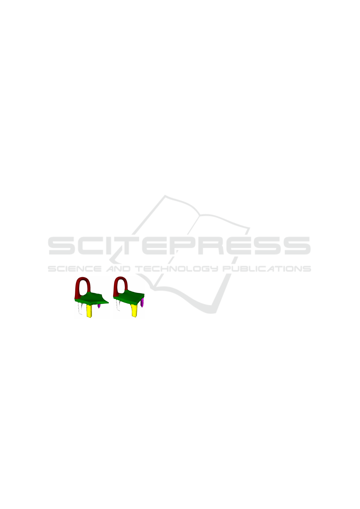
In Figure 4(b) we already introduced the exam-
ple of a chair, whose seating surface should vary in
length. With the help of the alternative deforma-
tion handle, the system was able to create a meta-
parameter to control this length. Figure 11 presents
some of the variations.
Finally, we tested the system with more complex
models that better resemble real world applications.
The procedural model of the plane used in Figure
Simplified Definition of Parameter Spaces of a Procedural Model using Sketch-based Interaction
229
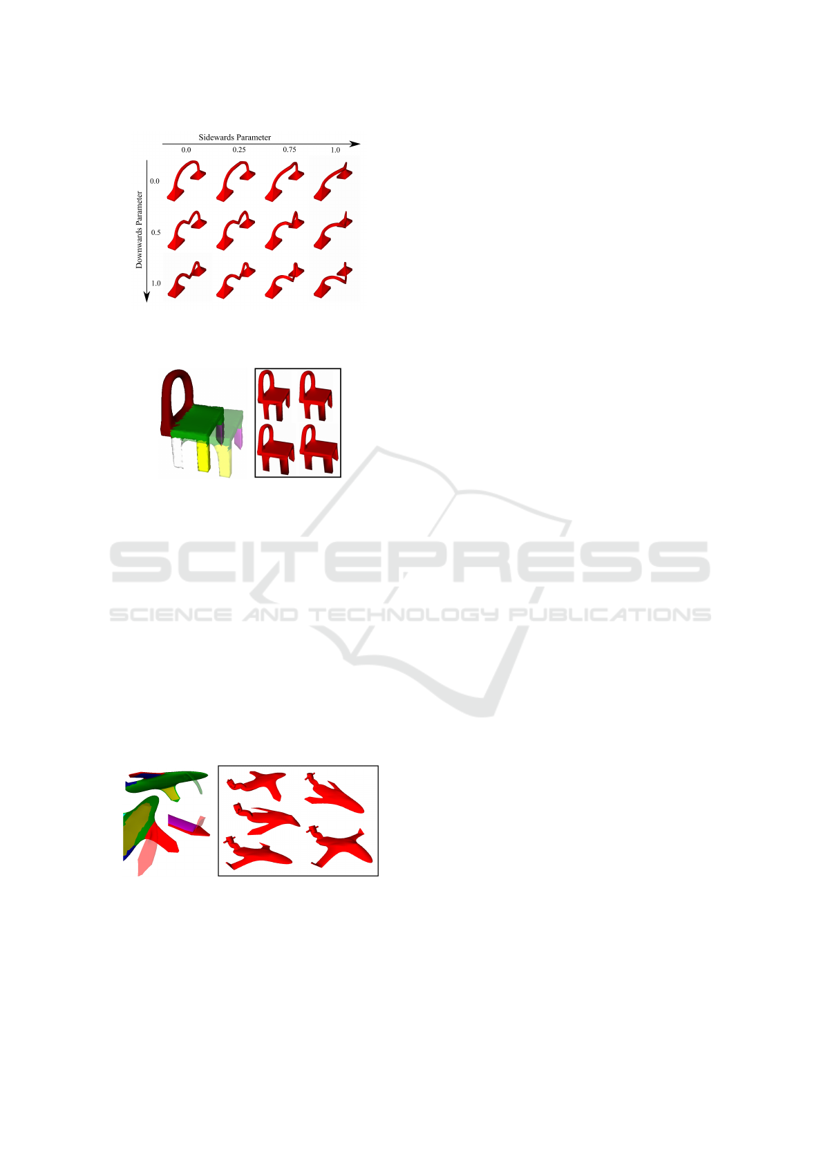
Figure 10: After a downwards and a sidewards deformation,
two parameters are inserted. A sampling of the parameter
space is shown.
(a) (b)
Figure 11: Using the segment-spanning face handle, the
chair was deformed (a). Figure (b) shows results of the
GML model with different parameter values.
12 is composed of 76 modeling commands and the
user introduced five meta-parameters that vary the an-
gle of the cockpit, the wings and their tips. With
the help of only five intuitive deformations, the user
quickly defined the desired parameter spaces and cre-
ated a procedural model that describes a range of dif-
ferent planes. Some of the deformations are visual-
ized in Figure 12(a). By varying the values of the
meta-parameters, the plane changes its structure in
the bounds of the defined object class. Figure 12(b)
shows a number of samples, generated by randomly
varying the meta-parameters between 0 and 1.
(a) (b)
Figure 12: Several deformations have been performed on
the mesh of a plane (a). Figure (b) gives results of the model
with multiple parameters using different values.
The system was presented to four test users with
a brief introduction of the functionality. They were
asked, if the interaction with the system was per-
ceived as intuitive. Both the sketch-based refinement
of the segmentation and the deformation matter in this
question. The users generally agreed, that the sketch-
based interaction was easy to use and had a flat learn-
ing curve. Furthermore, it was asked if the resulting
parameterized model represents what the user had in
mind prior to the interaction. After trying out the sys-
tem for five minutes, the users understood the effects
of the different deformation handles and were able to
create predictable results.
However, the dependability on the deformation al-
gorithm is a major limitation. Our technique can only
create meta-parameters that follow the deformation
steps. To overcome this limitation more user inter-
action would be needed. For example an inflation
tool could be used to vary the scales of a RotationEx-
trude. Furthermore, the degrees of freedom of the
GML model are limited. A SketchExtrude command
only performs a fixed number of extrude operations,
thus it cannot interpolate every arbitrary deformation.
Inserting another extrude in the middle of the script
to increase the degree of freedom is not possible, be-
cause the sketch-based modeling tool our technique
is based on uses an id-based system to reference each
face. Another extrude inserts more faces, making the
face references of the subsequent commands invalid.
6 CONCLUSION AND FUTURE
WORK
We presented a technique to intuitively insert meta-
parameters into a procedural GML model with the
help of sketch-based interaction. The system derives
global offset positions from the GML commands.
These are then anchored in the evaluated surface mesh
by finding reference vertices and saving their spatial
relationship to the global positions. During a defor-
mation, the points are tracked and the path of the
offsets is approximated with B-spline curves. These
are then inserted into the procedural algorithm and
evaluated according to the value of a corresponding
meta-parameter. To ensure ease of use, an automatic
segmentation provides deformation targets that can
be refined using sketch-based interaction. Also, the
behavior of the deformation algorithm can be easily
adapted. The results validated that the proposed tech-
nique is a powerful tool, opening the possibilities of
procedural modeling to a broader audience.
In the future we plan to extent the variations that
can be defined with a meta-parameter. Perceptual
knowledge can help to identify changes that seem nat-
ural to the user and can be used to improve the defor-
mation process. Also, the integration of the modeling
GRAPP 2018 - International Conference on Computer Graphics Theory and Applications
230

tool and our system will help to overcome the latter
limitation.
REFERENCES
Bein, M., Havemann, S., Stork, A., and Fellner, D. (2009).
Sketching subdivision surfaces. Sketch Based Inter-
faces and Modeling, pages 61–68.
Bernhardt, A., Barthe, L., Cani, M. P., and Wyvill, B.
(2010). Implicit blending revisited. Computer Graph-
ics Forum, 29(2):367–375.
Bessmeltsev, M., Vining, N., and Sheffer, A. (2016). Ges-
ture3D: Posing 3D Characters via Gesture Drawings.
ACM Transactions on Graphics, 35(6):165:1–165:13.
Botsch, M. and Kobbelt, L. (2004). A Remeshing Approach
to Multiresolution Modeling. Proceedings of the 2004
Eurographics ACM SIGGRAPH symposium on Geom-
etry processing SGP 04, page 185.
Choi, B., i Ribera, R. B., Lewis, J. P., Seol, Y., Hong, S.,
Eom, H., Jung, S., and Noh, J. (2016). SketchiMo:
Sketch-based Motion Editing for Articulated Charac-
ters. ACM Transactions on Graphics, 35(4):1–12.
De Paoli, C. and Singh, K. (2015). SecondSkin: Sketch-
based Construction of Layered 3D Models. Acm
Transactions on Graphics, 34(4):10.
Eitz, M., Hildebrand, K., Boubekeur, T., and Alexa, M.
(2010). Sketch-based 3D shape retrieval. In ACM
SIGGRAPH 2010 Talks on - SIGGRAPH ’10, page 1,
New York, New York, USA. ACM Press.
Eitz, M., Richter, R., Boubekeur, T., Hildebrand, K., and
Alexa, M. (2012). Sketch-based shape retrieval. ACM
Transactions on Graphics, 31(4):1–10.
Fish, N., Averkiou, M., van Kaick, O., Sorkine-Hornung,
O., Cohen-Or, D., and Mitra, N. J. (2014). Meta-
representation of shape families. ACM Transactions
on Graphics, 33(4):1–11.
Getto, R., Merz, J., Kuijper, A., and Fellner, D. W. (2017).
3D meta model generation with application in 3D ob-
ject retrieval. Proceedings of the Computer Graphics
International Conference on - CGI ’17, pages 1–6.
Havemann, S. (2005). Generative mesh modeling. PhD
thesis.
Havemann, S. and Fellner, D. W. (2003). Technical Report
TUBS-CG-2003-01 Generative Mesh Modeling. On-
line.
Herman, G. T., Rozenberg, G., and Lindenmayer, A.
(1975). Developmental systems and languages.
North-Holland Pub. Co.
Igarashi, T., Matsuoka, S., and Tanaka, H. (1999). Teddy:
a sketching interface for 3D freeform design. Pro-
ceedings of the 26th annual conference on Computer
graphics and interactive techniques - SIGGRAPH ’99,
pages 409–416.
Jorge, J. and Samavati, F., editors (2011). Sketch-based In-
terfaces and Modeling. Springer London, London.
Kazmi, I. K., You, L., and Zhang, J. J. (2014). A Survey
of Sketch Based Modeling Systems. 2014 11th Inter-
national Conference on Computer Graphics, Imaging
and Visualization, pages 27–36.
Kim, V. G., Li, W., Mitra, N. J., Chaudhuri, S., DiVerdi,
S., and Funkhouser, T. (2013). Learning part-based
templates from large collections of 3D shapes. ACM
Transactions on Graphics, 32(4):1.
Lindenmayer, A. (1968). Mathematical models for cellular
interactions in development. II. Simple and branching
filaments with two-sided inputs. Journal of theoretical
biology, 18(3):300–315.
Nealen, A., Igarashi, T., Sorkine, O., and Alexa, M.
(2007). FiberMesh. ACM Transactions on Graphics,
26(99):41.
Pagano, R. R. (2013). Understanding statistics. Oxford
University Press.
Parish, Y. I. H. and M
¨
uller, P. (2001). Procedural Modeling
of Cities. 28th annual conference on Computer graph-
ics and interactive techniques, (August):301–308.
Schmidt, R. and Singh, K. (2008). Sketch-based procedural
surface modeling and compositing using surface trees.
Computer Graphics Forum, 27(2):321–330.
Schmidt, R., Wyvill, B., Sousa, M. C., and Jorge, J. a.
(2005). ShapeShop: sketch-based solid modeling with
BlobTrees. EUROGRAPHICS Workshop on Sketch-
Based Interfaces and Modeling.
Shapira, L., Shamir, A., and Cohen-Or, D. (2008). Con-
sistent mesh partitioning and skeletonisation using
the shape diameter function. Visual Computer,
24(4):249–259.
Sorkine, O. and Alexa, M. (2007). As-Rigid-As-Possible
Surface Modeling. Proceedings of the fifth Euro-
graphics symposium on Geometry processing, pages
109–116.
Tobler, R. F., Maierhofer, S., and Wilkie, A. (2002). Mesh-
Based Parametrized L-Systems and Generalized Sub-
division for Generating Complex Geometry. Interna-
tional Journal of Shape Modeling, 08(02):173–191.
Wyvill, B., Guy, A., and Galin, E. (1999). Extending the
CSG tree. Warping, blending and Boolean operations
in an implicit surface modeling system. Computer
Graphics Forum, 18(2):149–158.
Simplified Definition of Parameter Spaces of a Procedural Model using Sketch-based Interaction
231
