
Simultaneous Measurement of a Blood Flow and a Contact Pressure
Ryo Inoue
1
, Hirofumi Nogami
2
, Eiji Higurashi
3
and Renshi Sawada
2
1
Graduate School of Systems Life Sciences, Kyushu University, Japan
2
Department of Mechanical Engineering, Kyushu University, Japan
3
Department of Precision Engineering, University of Tokyo, Japan
Keywords: Optical Sensor, Blood Flow, Contact Pressure, Laser Doppler, MEMS.
Abstract: Although a number of laser Doppler blood flow sensors have been developed over the past few decades, they
remain uncommon in practice. This is because the contact pressure between the skin and the sensor is not
measured simultaneously with blood flow, despite the fact that blood flow is greatly affected by contact
pressure. Thus, reliable and highly reproducible measurement of blood flow could not yet be realized. In
addition, changes in beam conditions or body temperature also have an effect on blood flow measurement.
Therefore, we fabricated a micro electro mechanical system (MEMS) blood flow sensor which can measure
contact pressure, beam power, and body temperature, for reliable and highly reproducible measurement.
1 INTRODUCTION
Continuous health monitoring systems using
biomedical sensors have been widely studied recently
to prevent certain diseases. Laser Doppler blood flow
meter has been studied to enhance health monitoring
systems because the monitoring of peripheral blood
flow just beneath the skin is intimately correlated
with health conditions and the nervous systems
(Wolfman Doehner et al., 2002. Julian M. Stewart et
al., 2004. M. Yasushi et al., 2003).
The laser Doppler flow meter is a non-invasive
method for measuring blood flow in the micro
circulation of biological tissue, and was established by
Stern et al. in 1977 (Stern, M. D. et al., 1977). The
device has been widely used in clinical medicine,
microcirculation, dermatology, and autonomic
function research. There are commercialized blood
flow meters such as the ADMEDEC Laser Doppler
blood flow meter (ALF21; ADVANCE CO., LTD),
stationary and optical fiber type blood flow meters
(OMEGAFLO; OMEGAWAVE, INC), and fiber-less
blood flow meter (RBF-101; Pioneer Corporation).
Moreover, the development of blood flow meters using
micro electric mechanical systems (MEMS)
techniques are currently the focus of active study to
achieve the goals of low power consumption, downsize
the dimensions of the sensor, and maintain low cost. In
an earlier study, the present authors fabricated an
integrated sensor for use in laser Doppler blood flow
measurement systems without optical fibres by
mounting laser diode and photo diode on silicon
substrate (E. Higurashi et al., 2003). Since then,
smaller blood flow sensors have been fabricated using
system line or wafer level packaging techniques (W.
Iwasaki et al., 2010. Y. Kimura et al., 2010).
Although a number of blood flow sensors have
been developed over the past few decades, they are
used in only medical field. This is because contact
pressure has not been considered while measuring
blood flow, despite the fact that blood flow is greatly
affected by it.
Figure 1 shows blood flow when contact pressure
is increased every 20 mmHg. When contact pressure
is lower (0-40 mmHg), the blood flow is larger and
the blood amplitude is smaller. Blood flow decreases
a little, but the amplitude increases when contact
pressure is between 60mmHg and 80mmHg. Finally,
blood flow is about one tenth of what is measured in
the 0mmHg case, and the amplitude decreases again
when it exceeds 100 mmHg. This is because the skin
tissue and vessels are elastic and their deformation via
contact pressure can change the blood stream. Contact
pressure increases linearly, but blood flow and
amplitude change in a non-linear fashion. Furthermore,
the influence of contact pressure on blood flow
measurement is dependent on individual differences
such as the hardness of the skin tissue and blood
pressure. Therefore, simultaneous measurement of
contact pressure is important for optimizing blood flow
measurement.
48
Inoue, R., Nogami, H., Higurashi, E. and Sawada, R.
Simultaneous Measurement of a Blood Flow and a Contact Pressure .
DOI: 10.5220/0006596800480053
In Proceedings of the 11th International Joint Conference on Biomedical Engineering Systems and Technologies (BIOSTEC 2018) - Volume 4: BIOSIGNALS, pages 48-53
ISBN: 978-989-758-279-0
Copyright © 2018 by SCITEPRESS – Science and Technology Publications, Lda. All rights reserved
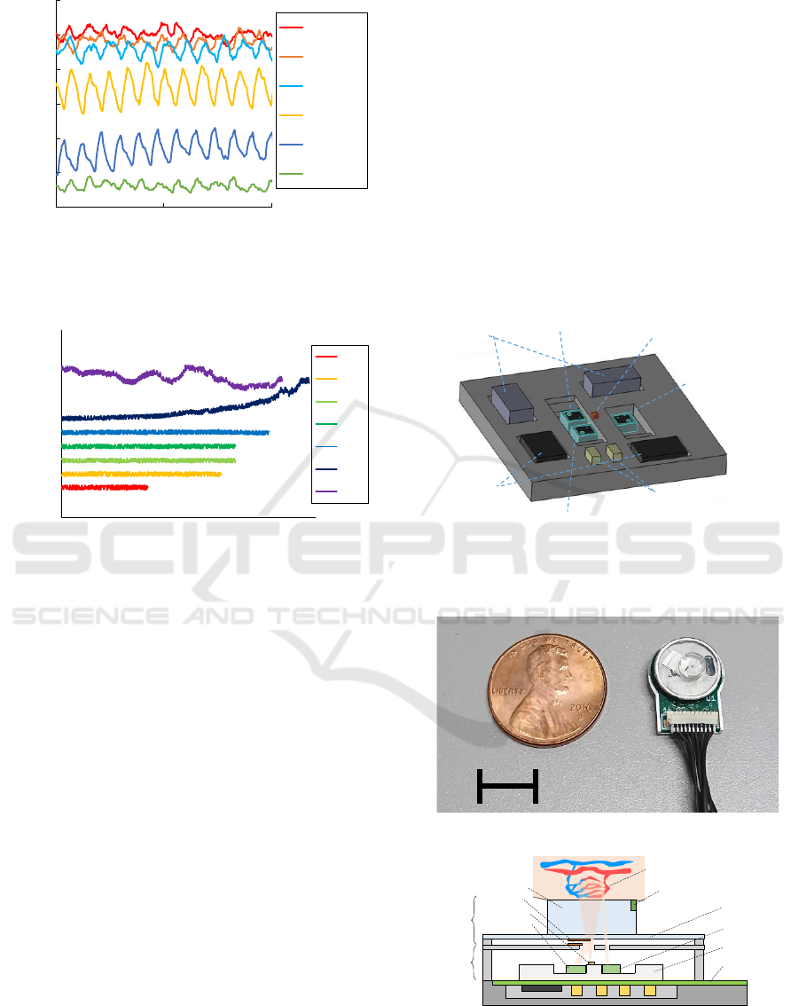
Figure 1: Blood flow under different patterns of contact
pressure.
Figure 2: beam monitoring under different patterns of drive
current.
In addition, Figure 2 shows the output of PD for
monitoring the laser beam from the vertical cavity
surface emitting laser (VCSEL) used in the blood
flow sensor. The beam power unsteadily changes in
response to a drive current and drive time and can also
be changed by environmental temperature. Unstable
beams undermine the authenticity of the data from
blood flow measurement. Therefore the simultaneous
monitoring of beam power is also important for
optimizing blood flow measurement.
A deep body temperature does not change
dramatically, but a temperature of contact point
between the sensor and the skin changes easily. A
blood flow is changed by blood vessel constriction
based on surrounding temperature. Thus,
measurement of contact point temperature is also
important for improving it.
In this study we propose a new structure for an
integrated blood flow sensor which can measure
blood flow and contact pressure simultaneously.
Moreover, the sensor has a monitoring system that
includes beam conditions and contact point
temperature to enhance blood flow measurement.
2 SENSOR
The integrated blood flow sensor chip was fabricated
by using a ceramics multi-stratified technique, and
consists of a vertical cavity surface emitting laser
(VCSEL), three photo diodes (PDs), Op-Amps,
several resistors and capacitors on the multi-layer
ceramics board, and is 6.5mm×6.5mm×1.3mm in
size, as shown in Figure 3. The blood flow sensor
module size is 10mm in diameter and 6.7 mm in
thickness, and is composed of a covering for the
integrated blood sensor chip with a metal cap and a
deformable cap which includes a polypropylene
sheet, an acrylic lug and a thermistor to measure the
contact point temperature (Figure 4).
Figure 3: A schematic of developed integrated blood flow
sensor chip.
(a)
(b)
Figure 4: (a) Blood flow sensor module and (b) diagram of
the cross section view of the sensor module and of the
measurement principle.
0
10
20
30
40
50
60
0 5 10
Blood flow [ml/min]
Time [s]
0mmHg
20mmHg
40mmHg
60mmHg
80mmHg
100mmHg
0
0.05
0.1
0.15
0.2
0.25
0 200 400 600 800
PD_out [V]
Time [s]
1mA
2mA
3mA
4mA
5mA
6mA
7mA
Resistors
VCSEL
Capacitors
Op Amps
Pressure
monitoring PD
Beam monitoring PD
Ceramics
board
Blood flow PD
10mm
PCB board
Ceramics board
PD
VCSEL
Metal
cap
Deformable
cap
Mirror
Acrylic lug
Deformable PP
sheet
Capillary vessels
Skin
PD
Thermistor
Simultaneous Measurement of a Blood Flow and a Contact Pressure
49
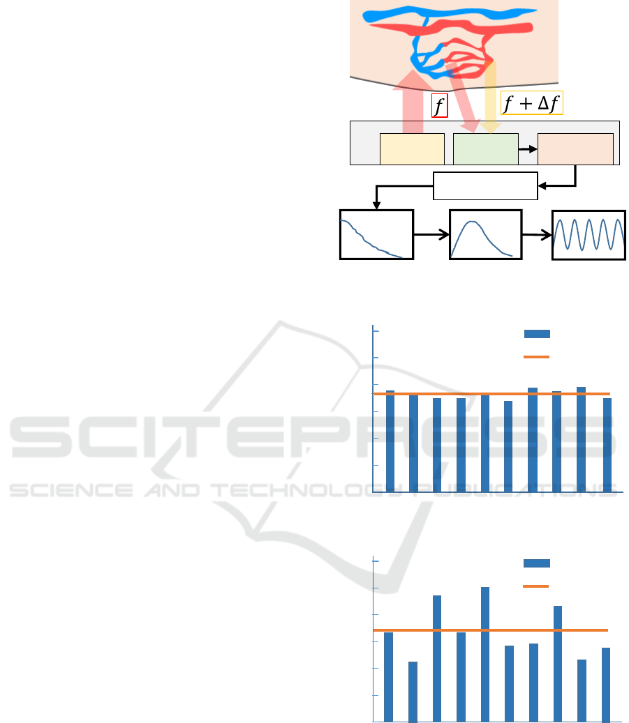
The laser beam from the VCSEL is emitted
radially, and as a result, the beam penetrates into skin
tissue or is reflected by the mirror on the metal cap
and on the back-side of the deformable cap. The laser
beam that is diffused into the skin tissue is back-
scattered. The backscattered light has two forms:
Doppler-shifted light caused by moving particles
(mainly the red blood cells of the capillary and
arteriole) and non-Doppler shifted light caused by
static tissue. The light was interfered with by the PD,
and intensity modulations related to blood velocity
were observed on the PD. The power spectrum of the
intensity modulations includes the random
characteristics of the velocity vector of blood
perfusion in the vessel. In such cases, blood flow is
calculated using the following formula.
< ω >=
∫
𝜔𝑃(𝜔)𝑑𝜔 (1)
The blood flow is proportionate to the averaged
velocity multiplied by the concentration, of Doppler
scattering particles. P(ω) is the power spectrum of
the frequency distribution, and < ω > is the first
moment of the power spectrum of the frequency
distribution. The statistically derived value, < ω > is
used as the blood flow as shown in Figure 5 (Y.
Kimura et al., 2010).
When contact pressure occurs between the acrylic
lug and skin tissue, the deformable polypropylene
sheet (PP sheet) bends down, the mirror attached to
the back of the PP Sheet also moves down in a vertical
direction, and the light reflected on the mirror is
detected by the pressure monitoring PD. The
monitoring PD output is changed in correspondence
to the vertical displacement which is related linearly
to the contact pressure (T. Iwasaki et al., 2015).
Ensuring that one light beam emitted from a VCSEL
chip functions as the light source for both the laser
blood flow sensor and laser displacement sensor
means that blood flow and contact pressure can be
measured simultaneously.
The mirror is attached to the top of the metal cap.
The light reflected on the mirror is detected by the
beam monitoring PD. Due to this, the sensor can
continuously check the beam power of the VCSEL.
Further, the acrylic lug can improve the
repeatability of blood flow measurement. The acrylic
lug can fix the contact area and the measurement
position. In a previous study, blood flow was
measured ten times; the mean blood flow and the
average of the ten measurements, with or without the
acrylic lug, are shown in Figure 6. The standard
deviation (SD) is improved dramatically by attaching
the acrylic lug (Ryo Inoue et al., 2016).
Figure 5: Principle of blood flow measurement.
(a)
(b)
Figure 6: Measurement of mean blood flow with the acrylic
lug attached (a) and without the lug (b).
VCSEL
Power spectrum
First moment Blood flow
PD
Op-Amp
FFT Analyzer
Capillary vessels
Skin
SD:2.03
1 2 873 4 5 6 9 10
5
30
25
20
15
10
0
Blood flow [ml/min]
Blood flow
Average
1 2 873 4 5 6 9 10
5
30
25
20
15
10
0
Blood flow [ml/min]
Blood flow
Average
SD:7.93
BIOSIGNALS 2018 - 11th International Conference on Bio-inspired Systems and Signal Processing
50

3 EXPERIMENTS
The experimental system was set as shown in Figure
7. The sensor was connected to the electric circuit
board. The power sources of the op-amp and VCSEL
were also connected to the board and the circuit sent
the data to the PC. LabVIEW was used to calculate
blood flow from the signal of the PD, as shown in
Figure 5, and to indicate and log the data of blood
flow, contact pressure, beam power, and contact point
temperature simultaneously.
Three experiments were conducted to check the
performance of the sensor. In the first experiment, the
simultaneous measurement of four data samples was
conducted using the experimental system. In addition,
the forearm of the subject was compressed with a cuff
to reduce the blood flow purposely. It took 10 seconds
to increase the pressure of the cuff from 0 mmHg to
300 mmHg. The cuff was then released after 15
seconds.
Next, a blower was used in place of putting the
finger in the experimental system. The blower blew
hot air (40 degrees) onto the sensor in order to check
the change of beam conditions using the beam
monitoring PD.
Finally, the subject pressed the sensor in three
stages of the contact pressure. The blood flow was
measured simultaneously while the contact pressure
changed continuously and stepwise.
4 RESULTS
Figure 8(a) shows the four data points given by the
simultaneous measurement using the sensor. Blood
flow was measured while keeping the output of the
pressure monitoring PD at about 50mV. When the cuff
started to compress the forearm of the subject, blood
flow decreased gradually. When cuff pressure was kept
at 300mmHg, blood flow did not change dramatically.
Then, blood flow suddenly increased to the original
value following release of the cuff. Further, the beam
power and contact point temperature values measured
by the sensor stayed constant.
Figure 8(b) shows the output of the beam
monitoring PD when the temperature around the
sensor was increased by the blower. Increasing the
temperature decreased the beam power. When the
blower was removed, a tendency to recover gradually
to the original voltage was shown. This indicates that
the beam of VCSEL is effected by operating
temperature and our sensor can measure it change
simultaneously.
Figure 7: Experimental system used to measure the blood
flow, the contact pressure, the beam power and the body
temperature simultaneously.
The blood flow in three stages of contact pressure
is shown in figure 8(c). The blood flow decreased
corresponding to the change of the contact pressure.
The blood amplitude also changed. It got larger by
increase of contact pressure (100 mmHg), and then
became smaller by the strongest press (200mmHg).
5 DISCUSSION
Figure 8(a) verifies the sensor can measure blood
flow, contact pressure, beam condition, and contact
point temperature simultaneously. In addition, blood
flow is changed by the cuff. For contact pressure
measurement, the calibration data need to be prepared
beforehand, but it will be helpful for blood flow
measurement to obtain reliable data. For example,
contact pressure data can be used for a feedback
control with programmable actuator by a
microcontroller in order to maintain appropriate
contact pressure range. The combination use this
sensor and an actuator can improved blood flow
measurement additionally.
Figure 8(b) shows the change of the output of
monitoring PD corresponding to operating
temperature. Beam power monitored by PD can be
also used for a feedback drive using an automatic
power control (APC) circuit. Figure 9 shows the APC
circuit to adjust the drive current of the VCSEL from
the difference between a reference voltage and the
output of the beam monitoring PD. This circuit
maintains constant beam power to achieve stable
blood flow measurement.
Blood flow changes in three stages depending on
the change of contact pressure. That also shows the
relation among a blood flow, a blood amplitude, and
V C SE L
P ow er
Circuit
Board
Op-A m p
P ow er
DAQ
Computer
(LabVIEW)
Sensor module
Finger
Simultaneous Measurement of a Blood Flow and a Contact Pressure
51
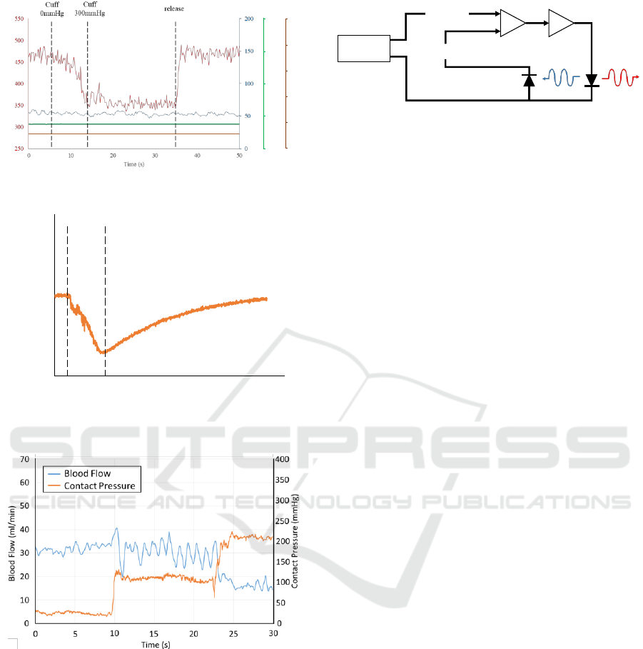
(a)
(b)
(c)
Figure 8: (a) the blood flow with under contact pressure of
80 mmHg, (b) the output of beam monitoring PD with a hot
air by dryer, and (c) the blood flow in three stages of the
contact pressure changed continuously and stepwise.
a contact pressure shown in figure 1. An indirect
blood pressure measurement method was suggested
by using the difference between the intravascular
pressure and the external pressure (M. Nogawa et al.,
2011). In their work, when this difference was small,
blood amplitude increased. When this difference is
zero, the blood amplitude vanished. It is difficult to
control intravascular pressure, as it depends on health
Figure 9: Automatic Power Control (APC) circuit
conditions such as whether the subject is being
measured before or after exercise or when the subject
is on a diet, but it is easy to control the value of the
external pressure. This value is controlled by
adjusting the contact pressure in this study. The
sensor can monitor it simultaneously, so larger and
clearer amplitude is obtained easily.
The sensor can provide new applications due to
realizing reliable blood flow measurement. For
example, the blood pressure determination conducted
by the relation between the intravascular pressure and
the contact pressure, and the stress detection by
heartbeat interval from blood amplitude (T. Akiyama
et al., 2015). In addition, a blood flow in a wave can
be obtained as a new biological information.
To use the sensor for various fields like these
applications, the error by the sensor should be smaller
than by the health conditions such as illness, before
and after exercise and so on. Our developed sensor
can make the error smaller by measuring four data
simultaneously.
4 CONCLUSIONS
The results verify that our new MEMS blood flow
sensor can measure blood flow, contact pressure,
beam power, and body temperature simultaneously.
This performance achieves more reliable blood flow
measurement than conventional sensors. Our
developed sensor is expected to have a wide range of
applications in the future since it is small enough to
be attached to the body and enables highly
reproducible measurement.
ACKNOWLEDGEMENTS
This research was partially supported by grants from
the Project of the Bio-oriented Technology Research
Advancement Institution, NARO (the research
project for the future agricultural production utilizing
artificial intelligence).
0
0.5
1
1.5
2
Beam Power (V)
0
8
Contact Point
Temperature (V)
2
10
6
4
Blood Flow
(ml/min)
Contact Pressure (mV
)
250
260
270
280
290
300
310
320
330
340
350
0 50 100 150 200
PD_Output (mV)
Time (s)
ON O F F
Power
source
PD output
Reference
Voltage
PD
VCSEL
Differential
amplifier
Amplifier
Monitor beam Mein beam
BIOSIGNALS 2018 - 11th International Conference on Bio-inspired Systems and Signal Processing
52

REFERENCES
E. Higurashi, R. Sawada and T. Ito. (2003). An integrated
laser blood flowmeter. Journal of light wave technology,
21(3), 591-595, doi:10.1109/JLT.2003. 809551.
Julian M. Stewart and Lesile D. Montgomery. (2004).
Regional blood flow volume and peripheral blood flow
in posture tachycardia syndrome. Am J Physiol Heart
and Circulatory Physiology, 287(3), 1319-1327. doi:
10.1152/ajpheart.00086.2004
M. Yasushi and M. Yanagidaira. (2003). Estimating
sleepiness during expressway driving. J. Int. Soc. Life
Inf. Sci., 21(2), 442-448.
M. Nogawa, T. Yamakoshi, K. Matsumura, S. Tanaka, M.
Ogawa, K. Motoi, and K. Yamakoshi. (2011). A New
Method for Indirect Determination of Systolic and
Diastolic Blood Pressure in the Radial Artery Using
Inflection-Points of Pressure-Volume Curves Based on
the Volume-Oscillometric Method (In Japanese).
Medical and Biological Engineering, 49(6), 968-976.
Ryo Inoue, Hirofumi Nogami, Ryuta Shiraishi, Yuki Seki
and Renshi Sawada. (2016). An acrylic lug for the
improved simultaneous measurement device of blood
flow and contact pressure. International Conference on
BioSensors, BioElectronics, BioMedical Devices,
BioMEMS/NEMS & Applications 2016 (Bio4Apps
2016): Gold Coast, QLD, Australia: Dec 2016.
Stern, M. D., Lappe, D. L., Bowen, P. D., Chimosky, J. E.,
Holloway, G. A., Keiser, H. R and Bowman, R. L..
(1977). Continuous measurement of tissue blood flow
by laser-Doppler spectroscopy. American Journal of
Physiology-Heart and Circulatory Physiology. 232(4),
441-448.
T. Iwasaki, T. Takeshita,Y. Arinaga, K. Uemura, H. Ando,
S Yakeuchi, M. Furue, E. Higuras and Renshi Sawada.
(2015). Shearing force measurement device with a
built-in integrated micro displacement sensor. Sensor
and Actuators A: Physical, 221, 1-8, doi: 10.1016/
j.sna.2014.09.029.
Wolfman Doehner, Nina Schoene, Mathias Rauchhaus,
Francisco Leyva-Leon, Darrell V. Pavitt, David A.
Reaveley, Gerhard Schuler, Andrew J. S. Coats,
Stefan D. Anker and Rainer Hambrecht. (2002). Effects
of Xanthine Oxidase Inhibition with Allopurinol
on Endothelial Function and Peripheral Blood Flow
in Hyperuricemic Patients with Chronic Heart
Failure – Results From 2 Placebo-Controlled Studies.
Circulation, 105, 2619-2624. doi: 10.1161/01.CIR.
0000017502.58595.ED
W. Iwasaki, H. Nogami, E. Higurashi and R. Sawada.
(2010). Miniaturization of a Laser Doppler Blood Flow
Sensor by System‐in‐Package Technology: Fusion of
an Optical Microelectromechanical Systems Chip and
Integrated Circuits. IEEE Transactions on Electrical
and Electronic Engineering. 5(2), 137-142. doi:
10.1002/tee.20508
Y. Kimura, M. Goma, A. Onoe, E. Higurashi and R.
Sawada. (2010). Integrated laser Doppler blood
flowmeter designed to enable wafer-level packaging.
IEEE Transactions on Biomedical Engineering. 57(8),
2026-2033. doi: 10.1109/TBME.2010.2043842
Simultaneous Measurement of a Blood Flow and a Contact Pressure
53
