Context Dependent Action Affordances and their Execution using an
Ontology of Actions and 3D Geometric Reasoning
Simon Reich, Mohamad Javad Aein and Florentin W
¨
org
¨
otter
Third Institute of Physics - Biophysics, Georg-August-Universit
¨
at G
¨
ottingen,
Friedrich-Hund-Platz 1, 37077 G
¨
ottingen, Germany
Keywords:
Action Affordances, Action Ontology, Planning, 3D Geometric Reasoning.
Abstract:
When looking at an object humans can quickly and efficiently assess which actions are possible given the
scene context. This task remains hard for machines. Here we focus on manipulation actions and in the first
part of this study define an object-action linked ontology for such context dependent affordance analysis.
We break down every action into three hierarchical pre-condition layers starting on top with abstract object
relations (which need to be fulfilled) and in three steps arriving at the movement primitives required to execute
the action. This ontology will then, in the second part of this work, be linked to actual scenes. First the
system looks at the scene and for any selected object suggests some actions. One will be chosen and, we use
now a simple geometrical reasoning scheme by which this action’s movement primitives will be filled with
the specific parameter values, which are then executed by the robot. The viability of this approach will be
demonstrated by analysing several scenes and a large number of manipulations.
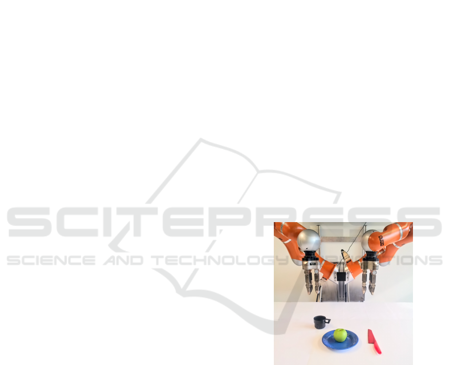
1 INTRODUCTION
From every day life we know that different scenes
suggest different actions, e.g. a plate, an apple, and
a knife – as shown in Fig. 1 – suggests a “cutting the
apple” action. However, assessing whether or not a
robot could actually do this, whether it should/could
do rather something else or whether not much can be
done at all given such scenes remains a difficult pro-
blem. It amounts to estimating the affordance of cer-
tain actions given the context provided by the scene.
One approach to solving this problem is to analyse
a scene and derive from it a symbolic representation,
which can then be used to find possible actions and/or
to do planning.
To achieve this, in (Rosman and Ramamoorthy,
2011) a complex network of geometrical relations
in the spatial and temporal domains is used. Via
Support-Vector-Machines (SVMs) topological featu-
res and symbolic meanings are learned. In (Sjoo and
Jensfelt, 2011) patterns of functional relationships are
defined, e.g. the object “work surface” with the action
“manipulate”. Similar, in (Liang et al., 2009) posture
templates are applied to the input data of each frame.
The resulting series of templates eventually forms a
library of actions. The authors use variable-length
Markov models for learning. In (Paul et al., 2016)
Figure 1: This scene contains a simple snack scenario. We
ask: what actions can be performed by the robot?
a common representation for abstract spatial relati-
ons and natural language is investigated. However,
(Konidaris et al., 2014) state that there cannot be one
perfect representation, but rather that “actions must
play a central role in determining the representational
requirements of an intelligent agent: a suitable sym-
bolic description of a domain depends on the actions
available to the agent.”
Staying closer to the actual motion patterns one
can also break down actions into segments, using –
for example – principal component analysis (PCA) as
in (Yamane et al., 2011). A motion sequence is here
218
Reich, S., Aein, M. and Wörgötter, F.
Context Dependent Action Affordances and their Execution using an Ontology of Actions and 3D Geometric Reasoning.
DOI: 10.5220/0006562502180229
In Proceedings of the 13th International Joint Conference on Computer Vision, Imaging and Computer Graphics Theory and Applications (VISIGRAPP 2018) - Volume 5: VISAPP, pages
218-229
ISBN: 978-989-758-290-5
Copyright © 2018 by SCITEPRESS – Science and Technology Publications, Lda. All rights reserved

projected into a state space, which is then mapped
to the first n principal components. In that reduced
state space a threshold is applied and the action is di-
vided into two parts. The same is iteratively applied
to each subspace until some exit criteria is met. The
resulting segments could then be interpreted as mea-
ningful action parts.
There are also non-vision based methods availa-
ble, for example in (Jamali et al., 2015) and (Jamali
et al., 2014), but these methods will not be discussed
any further, as we are focusing on vision here.
All these approaches are problematic, because it
remains difficult to smoothly link sensor signals (e.g.
from scene analysis) to symbolic action concepts and
then back to the signal domain for creating the trajec-
tories needed for the execution of an action by a ro-
bot. There is a danger of too strongly focusing on the
symbolic side or of remaining too close to the signal
domain.
Here we focus on manipulation actions and one
goal of the current study is to improve on this by intro-
ducing a deeper hierarchy of several layers between
signals and symbols for analysing a scene in a given
action context. We ask: What is needed to push (or
pick, or cut, etc.) a certain object? Which are the ge-
neral preconditions required for this regardless of the
actual objects in the scene? And – if those hold – are
also the specific conditions met to actually do it?
We build on the Semantic Event Chains (SECs)
framework (Aksoy et al., 2011) but we extend them
in several ways. SECs are matrices that show how
touching relations between pairs of objects change
during an action. The entries of the SEC matrix are
(“T”) for Touching, (“N”) for Not touching and (“A”)
for Absent relation. A manipulation action is segmen-
ted at keyframes which are moments that a touching
relation changes. The original SEC framework did
not much care about objects. Here, based on an ol-
der study (W
¨
org
¨
otter et al., 2012), we will now incor-
porate (still abstract) object roles to build an object-
action-linked ontology of manipulations, where these
object roles define the general preconditions that need
to be met to perform a certain action at all. On top of
this, we introduce a simple framework for geometric
reasoning, which allows the machine to check specific
preconditions, too, to finally execute an action.
In this study the robot selects one object in a scene
and asks – like a child during play – what could I do
with it? The framework will then analyse the situa-
tion and suggest possible manipulation actions, the-
reby addressing the problem of context dependent af-
fordances.
2 METHOD
This section divides into two parts: 1) definition of the
ontology and 2) algorithm to arrive at robotic execu-
tion of manipulation actions using the ontology given
an observed scene. We start with the first aspect.
2.1 Ontology of Manipulation Actions
We use all manipulation actions defined in (W
¨
org
¨
otter
et al., 2012) and create a new ontology by incorpora-
ting three layers: 1) abstract object relations (SEC),
2) object topologies and also 3) action primitives. Be-
fore doing this we need to define the roles of an object
in a more general way.
Defining Object Roles: Those are determined by the
changes that occur following an action in the rela-
tion of an object to other objects. An action invol-
ves at least two objects: a hand and a main object.
Resulting object categories (hand, main, primary, se-
condary, etc.) and their abstract roles are defined as
follows:
• Hand (The object that performs the action): not
touching anything at the beginning and the end of
action. It touches at least one object.
• Main (The object which is directly in contact with
the hand): not touching the hand at the beginning
and the end of action. It touches the hand at least
once.
• Primary (The object from which the main ob-
ject separates): initially touches the main object.
Changes its relation to not-touching during the
action.
• Secondary (The object to which the main object
joins): initially does not touch the main object.
Changes its relation to touching during the action.
• Load (The object which is indirectly manipu-
lated): does not touch the hand. During the
action either touches/untouches the main and un-
touches/touches container.
• Container (The object whose relation with load
changes and it is not the main object): touches or
untouches the load object.
• Main support (The object on which the main ob-
ject is located): touching the main object all the
time.
• Primary support (The object on which the pri-
mary object is located): touching the primary ob-
ject all the time.
• Secondary support (The object on which the se-
condary object is located): touching the secondary
object all the time.
Context Dependent Action Affordances and their Execution using an Ontology of Actions and 3D Geometric Reasoning
219
1 2 3 4 5
Pushing.
p.s = m.s = s.s
p
m
s
p.s = m.s = s.s
p
m
s
p.s = m.s = s.s
p
m
s
p.s = m.s = s.s
p
m
s
p.s = m.s = s.s
p
m
s
(a) Action 1: Pushing.
1 2 3 4 5
Pick & Place.
p.s
s.s
p
m
s
p.s
s.s
p
m
s
m
p.s
s.s
p
m
s
m
p.s
s.s
p
s
mm
p.s
s.s
p
s
m
(b) Action 2: Pick and place.
1 2 3 4 5
6
7
Unloading.
p.s
s.s
Cont
p
m
L
s
p.s
s.s
Cont
p
m
L
s
m
L
p.s
s.s
Cont
p
m
L
s
m
L
p.s
s.s
Cont
p
L
m
s
m
p.s
s.s
Cont
p
L
m
s
m
p.s
s.s
Cont
p
L
s
mm
p.s
s.s
Cont
p
L
s
m
(c) Action 3: Unloading.
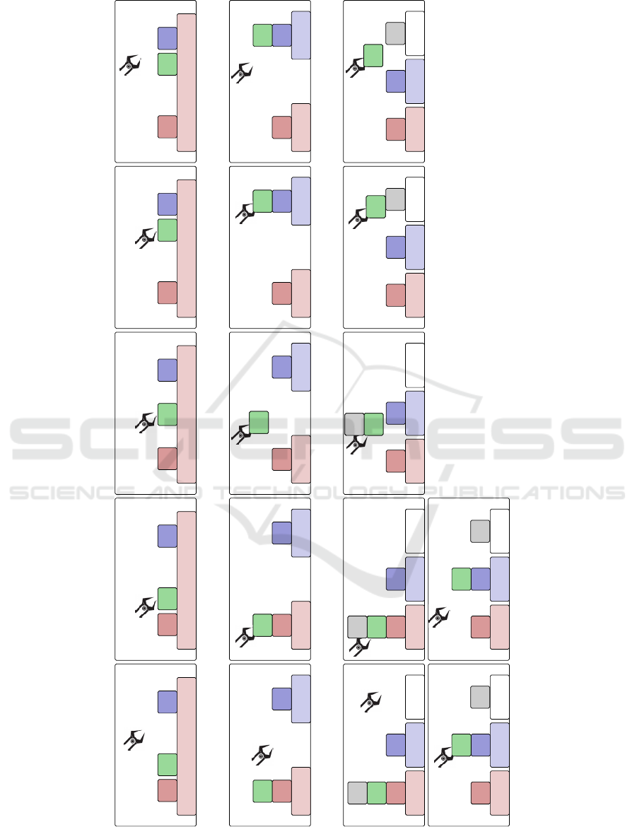
Figure 2: Schematic of actions in the ontology are shown for the three categories. From each category only one action is
shown. The objects are marked using the following convention: h = hand, m = main m.s = main support, p = primary,
p.s = primary support, s = secondary, s.s = secondary support, L = Load, and Cont = Container.
VISAPP 2018 - International Conference on Computer Vision Theory and Applications
220

• Tool (The object which is used by the hand to en-
hance the quality of some actions): touching the
hand all the time.
Action categories are based upon the objects,
which the hand interacts with. These fall into three
categories:
1. Actions with main support: In this category the
main object is always in touch with the main sup-
port; An example is shown in Fig. 2a.
2. Actions without main support: In this category the
main object is lifted from the main support; Nn
example is shown in Fig. 2b.
3. Actions with load and container: In this category a
container with load, e.g. a glass filled with water,
is used; An example is shown in Fig. 2c.
and several actions usually exist for each group. A
more detailed list of actions is shown in Tab. 1. The
full definition of the ontology is shown elsewhere
1
.
Now we can define the layers of the ontology.
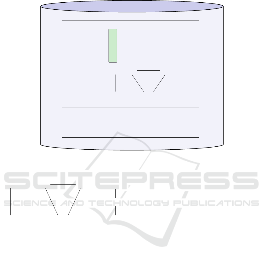
Layer 1) SEC based Object Relations at Start: The
individual graphical panels in Fig. 2 represent the co-
lumns of a Semantic Event Chain ( which reflect the
transition of object relations and are the necessary
conditions for successful execution). Fig. 2b shows a
pick and place action; its corresponding SEC is shown
in the upper part of Fig. 3. The first column shows
the SEC-defined pre-conditions. If and only if these
touching relations are not violated, the action could
commence. But this is not yet sufficient.
Layer 2) Object Topologies: All actions are always
performed at the main object and this will only be
possible if the SEC-pre-condition hold and if the
main object appears in the scene with certain topolo-
gical connections to other objects. The middle part of
Fig. 3 shows which topologies are permitted for pick
and place.
Remarkably there are only three possible topolo-
gical relations to which all scenes that include the
main object can be reduced. To achieve this the
complete connectivity graph of who-touches-whom
will be reduced into those subgraphs that contain the
main object. Each subgraph consists of at least the
main object and the support, and, if directly touching
neighbors exist, only one directly touching neighbor
(Fig. 4). There are three cases:
1. The main object has only one touching relation.
The touched object is a support, e.g. a table (see
Fig. 4, left). A real world example is shown in
Fig. 7b; the blue plate is on top of the board and
the board becomes the support.
1
http://www.dpi.physik.uni-goettingen.de/cns/
index.php?page=ontology-of-manipulation-actions
2. The main object has two touching relations. One
is a support, the second one is another object,
which is also touching the support (see Fig. 4,
middle). In Fig. 7b, the apple touches its support
(green plate) and the yellow pedestal which is on
the same support.
3. The main object has two touching relations. It
touches its support and another object, which does
not touch the support (see Fig. 4, right). In Fig. 7b,
the pedestal is on top the green plate and the jar
is on top of the pedestal (but does not touch the
green plate).
These subgraphs determine the remaining precon-
ditions. For example, a tower structure as shown in
Fig. 4 (right graph) is not allowed for pick and place
and pushing actions.
Layer 3) Movement Primitives: SEC pre-conditions
and topological pre-conditions define the first two lay-
ers of the ontology. The third and last layer is a set of
movement primitives, which are needed to execute the
action.
For the pick and place action, the primitives are
shown at the bottom of Fig. 3. The complete list of
primitives for all actions is shown on the web page.
How to fill these abstract primitives with execution
relevant parameters will be described later and the
process of execution of actions is then the same as
in (Aein et al., 2013).
One primitive shall be explained in more detail:
The move(ob ject, T ) primitive sends a command to
the robot to move to a pose which is determined by
applying transform T to the pose of ob ject. The trans-
form T has two parts, a vector p which shows the
translation, and a matrix R which shows the rotation.
For example, when we want to grasp the main object,
we perform a move(main, T ) primitive to move the
robot arm end effector to a proper pose for grasping.
Since we want the end effector to reach the main ob-
ject, the vector p in this case is equal to zero. Ho-
wever, the rotation part R needs to be set such that
the robot approaches the main object from a proper
angle. This is necessary to avoid possible collisions
with other objects near the main.
2.2 Algorithm for
Execution-Preparation
Fig. 5 shows an overview of the algorithm used for
robotic execution of the above defined actions. Most
components rely on existing methods and will not be
described in detail.
We start with (1) an RGB-D recorded scene which
is (2) segmented using the LCCP algorithm (Stein
Context Dependent Action Affordances and their Execution using an Ontology of Actions and 3D Geometric Reasoning
221

Table 1: Summary of ontology of actions. Actions are divided into three categories and further into sub-categories. There can
be more than one action in each sub-category.
Category Sub-Category Example Actions
Actions with main support
Actions with hand, main and main support push, punch, flick
Actions with hand, main, main support and primary push apart, cut, chop
Actions with hand, main, main support and secondary push together
Actions with hand, main, main support, primary and se-
condary
push from a to b
Actions without main
support. (These action have
primary, secondary and their
supports)
primary 6= secondary and primary support 6= secondary
support
pick and place, break
off
primary 6= secondary and primary support = secondary
support
pick and place, break
off
primary 6= secondary and primary = secondary support put on top
primary 6= secondary and primary support = secondary pick apart
primary = secondary
pick and place, break
off
Actions with load
and container
The relation of load and main changes from N to T (lo-
ading)
Pipetting
The relation of load and main changes from T to N (un-
loading)
Pour, Drop
et al., 2014) into different objects from which (3) a
graph is created with edges between objects that touch
each other. (4) Then we randomly choose one ob-
ject as main. (5) The complete list of all conside-
red manipulation actions, of which there are 29 (see
Tab. 2), is derived from (W
¨
org
¨
otter et al., 2012) (only
3 are indicated in Fig. 5) and (6) for all of them we
use the first layer of the ontology to check whether
the main object in this scene fulfills their SEC pre-
conditions. This leads to (7) computation of all pos-
sible subgraphs for main and for those we check (8)
with the second layer of the ontology the topological
pre-conditions by which the list gets reduced. Now
we can (9) use the third layer and extract from the on-
tology the required action primitives. This concludes
the preparation stage and this information is sent to
the execution engine.
2.3 Execution-Parameterization:
Geometric Reasoning
In order to execute any of the in-principle-possible
actions we need to parameterize them. In general
we use our action library from (Aein et al., 2013)
where the required parameters are all defined. They
directly map to the action primitives from stage (9)
of the above described algorithm. Thus, we need to
now consider the actual scene layout to find possi-
ble parameter ranges for these movement primitives.
For this we employ geometric reasoning. The goal
of this is that given an action and its main object we
want to find the directions which are free to manipu-
late this object. These directions are directly used to
define parameter ranges of the action primitives (e.g.
move(ob ject, T )) for action execution.
A step-by step explanation of the geometric rea-
soning algorithm is shown in Fig. 6. For visualization
purposes we will analyze the relative position of two
cubes to each other: one green and one blue. In a very
simple approach, one could reduce the objects to one
point in space, for example the mean or average po-
sition. This however will ignore object sizes as well
as shapes. Instead, we want a more general solution,
which does not depend on object size, shape, or dis-
tance.
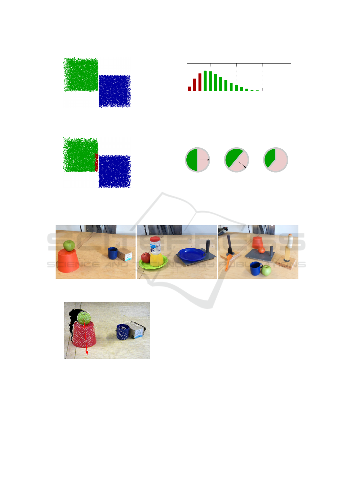
First, we compute the distance from each voxel
from one cube to each voxel in the other cube and
bin the distance as shown in Fig. 6b. For two sym-
metrical objects we expect a poisson shaped distribu-
tion. We will use all voxels, which are below the first
maximum and belong to the green cube; these points
are marked red in the histogram. The corresponding
voxels are marked in Fig. 6c in red, too. Next, we
compute the normals of these voxels. They will, as
per definition, point away from the green cube. These
normals are clusterd using a k-means clustering algo-
rithms. While undersegmentation will be harmful –
as not all directions are found – but oversegmentation
is not, a k that is greater than the expected number of
directions is used. We found k ≈ 8 leads to good re-
sults for most real-world examples. Lastly, we spawn
a half sphere around each resulting cluster (half cir-
cle in 2d as shown in the example in Fig. 6d). The
union of all spheres points to the blocked directions,
which is marked in red in the example – the direction
VISAPP 2018 - International Conference on Computer Vision Theory and Applications
222
Ontology Repository
State 1 2 3 4 5
hand, main N T T T N
main, primary T T N N N
main, secondary N N N T T
main, p.s N N N N N
main, s.s N N N N N
Primitive 1
move move move
ungrasp
(main) (prim.) (sec.)
Primitive 2 grasp
move
(free)
S
M
S
M O
S
M
O
permitted permitted non-permitted
Figure 3: This figure shows one example action, pick and place, in the proposed ontology repository, which is also shown
in Fig. 2b. It consists of three parts: the SECs (top), including the SEC precondition (top with green bar), topological
preconditions (middle), and primitives (bottom). “M” is the main object; “O” depicts other objects in the scene, and “S”
stands for support.
S
M
S
M O
S
M
O
Figure 4: All complex graph structures can be reduced to
one of these three graphs. “M” is the main object; “O” de-
picts other objects in the scene on which there are no further
information. The support is “S”.
where the blue cube is located at. This computation
is performed for each object, which is in a certain ra-
dius around the main object. The radius is hardware
dependent and defined by how much space the robot
hand needs to safely grasp or push an object.
The results of this type of reasoning on real scenes
will be shown in Section 3.
3 EXPERIMENTS
3.1 Setup and Experiments
We tested the algorithm in a ROS based system. A
Microsoft Kinect collects image and depth informa-
tion, in addition a high resolution Nikon DSLR ca-
mera is used for image refinement. We use (Schoeler
et al., 2014) for object recognition and pose estima-
tion. For model tracking (Papon et al., 2013) is used.
Our robot is a Kuka LWR arm which executes actions
as described in (Aein et al., 2013). Fig. 7 shows three
scenes that are used for testing:
1. A cup is next to a box and an apple is on top of a
pedestal.
2. The scene that we used in previous sections: a
plate on top of a cutting board, and an apple on a
plate. Touching the apple there is a pedestal with
a jar on top
3. A cluttered kitchen scene with many objects.
3.2 Results
Using these scenes, we analyse first the effect of the
top two layers of the ontology asking: Given a main
object, which actions are in principle permitted. Next,
we will consider the third ontology layer and perform
geometric reasoning on some examples to show how
actual action parameterization can be performed and
finally we will perform some actions with the robot.
Context Dependent Action Affordances and their Execution using an Ontology of Actions and 3D Geometric Reasoning
223

Scene
Segmentation Graph computation
Select main object, e.g. Apple
List of all candidate
actions from ontology
Check SEC preconditions
for all candidate actions
Create subgraph for main obj.
Check topological preconditions
for all candidate actions
Select one allowed action
Table
Green plate
Pedestal
Apple
Jar
Board
Blue plate
Table
Green plate
PedestalMain
Jar
Board
Blue plate
pick&
place
apple
green
plate
blue
plate
cut apple
pick&
place
apple jar
green
plate
. . . . . . . . . . . .
pick&place X
cut X
pick&place X
main must
touch
primary
. . . . . .
Support
Primary
Main
pick&place X
cut X
main must
not touch
any objects
pick&place X
. . . . . .
Combine primiti-
ves and geometrical
reasoning, execute
selected action on robot.
1 2
3
4
5 6
7
8
9
Figure 5: The steps of our proposed framework for scene affordances and execution are summarized here. Starting with a
real world scene (1), we perform object segmentation (2), object recognition, and graph calculation (3). The user selects a
main object, for example the apple (4). Afterwards, a list of candidate actions based on the ontology is produced (5). The
possibility of performing these actions is investigated in two steps by using the preconditions inside the ontology. First,
we check preconditions based on the SEC domain; in the example “pick&place the apple from green plate to blue plate is
allowed”, also cutting. However, “pick&place the apple from the jar to the green plate” is not, since the apple does not touch
the jar (6). We create the subgraphs around the main object, as shown in Fig. 4 (7). Afterwards, we check for topological
restrictions (8). Here, the action “cut the apple” fails, as the main object must not touch any other objects. This results in a
list of allowed actions. One action is selected (either by algorithm, or human), the primitives are read from the ontology and
sent to the execution engine. In case of move(ob ject) primitives, we perform the proposed geometric reasoning to get the
parameters.
3.2.1 Action Affordances
The results of action affordances for the three scenes
are calculated by using the preconditions of the onto-
logy and analysis of subgraph structures. The results
are summarized in Tab. 2. Each column shows the
possibility of performing different actions in the on-
tology for a specific selection of main, primary and
secondary objects.
Here, we can see some limitations of the SEC
domain. Some actions require additional high level
object knowledge (e.g. stirring or levering) and are
marked with “n”; for example stirring is always de-
nied as it requires a liquid and a container shaped ob-
ject (non-permanent objects pose a big problem for
SECs or planning in general). These properties can-
not be measured in the SECs domain. One could ar-
gue that also cutting, kneading, or scooping needs ad-
ditional high level object knowledge, but on the tou-
ching relations level these preconditions can be ensu-
red.
3.2.2 3D Geometrical Reasoning
Qualitative results of geometric reasoning are shown
in Fig. 8, Fig. 9, and Fig. 10. These results show
that by processing the low level point clouds one can
detect the blocked and free directions of a given ob-
ject. Some limitations can be found in Fig. 9a, which
shows the spatial relation between an apple and a
green plate. We expect that we can compute the nor-
mals of the point cloud, but at corners, e.g. at the
VISAPP 2018 - International Conference on Computer Vision Theory and Applications
224
(a) Two blocks serve as an example for geome-
tric reasoning. The possible movement direction
of the green cube without touching the blue one is
of interest.
5 10 15
Count
Binned distance
(b) The distances from all voxels of the green block to all voxels from
the blue block are binned. In the next step all voxels of the green
block, which are below the maximum, are used. They are marked in
red in the above histogram.
(c) The points found voxels found in Fig. 6b are
marked in red. The normals of these voxels are
computed and clustered using k-means..
+
=
(d) A half sphere around each of the k resulting vectors is spawned
(here: half circle for visualization) and the union of all spheres com-
puted. The union, above marked in red, marks the “forbidden” di-
rections.
Figure 6: Step-by-step explanation of the geometric reasoning algorithm.
(a) Scene 1. (b) Scene 2.
(c) Scene 3.
Figure 7: These three scenes are used to test the algorithms.
Figure 8: Qualitative results for the geometrical reasoning
method. The algorithm is applied to the object pair apple
and red pedestal. For graphical purposes only the largest
cluster is shown with a red arrow. The computational steps
for the arrow are detailed in Fig. 6d. Here, the arrow points
from the apple downwards to the pedestal, which is the “for-
bidden” direction.
border of object point clouds, this assumption is not
always met and the resulting access angles are off. In
Fig. 9a, the apple is captured with only few points into
the direction downwards to the green plates and the
resulting vector goes off to the side and barely through
the plate.
Another problem can be seen in scene 3. In
Fig. 10c, the relations between the orange spoon and
the black spoon in the spoon holder (black spoon
and spoon holder are recognized as one object) form
one unexpected cluster downwards, all others point
towards the spoon. Careful examinations show that
there actually are some points belonging to the spoon
base below the orange spoon and that the arrow down-
ward is justified. However, the resulting access angle
is very small.
3.2.3 Action Execution
The results of action execution are presented in the
video attachment of the paper (please see aforemen-
tioned web page). The execution of three different
Context Dependent Action Affordances and their Execution using an Ontology of Actions and 3D Geometric Reasoning
225
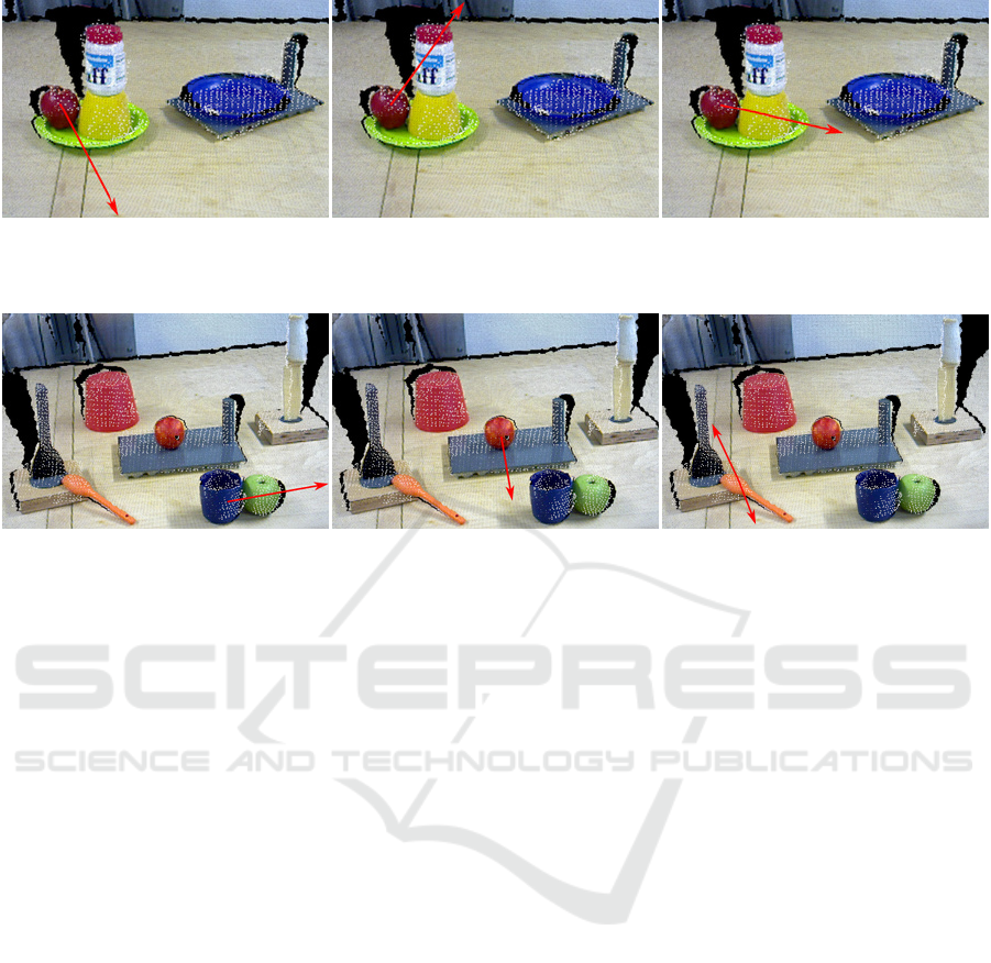
(a) Scene 2: Apple and green plate. (b) Scene 2: Apple and jar. (c) Scene 2: Apple and pedestal.
Figure 9: Qualitative results for the geometrical reasoning method. For graphical purposes only the largest cluster is shown
with a red arrow.
(a) Scene 3: Blue cup and apple. (b) Scene 3: Orange and board. (c) Scene 3: Orange and black spoon.
Figure 10: Qualitative results for the geometrical reasoning method for a cluttered scene. For graphical purposes only the
largest cluster is shown with a red arrow. In (c) the two largest clusters are depicted using red arrows.
actions is shown: “pushing”, “pick and place”, and
“put on top”. Selected frames of these experiments
are shown in Fig. 11. Shown are the actions “pus-
hing” (left), “pick and place” (middle), and “put on
top” (right).
4 CONCLUSION
The goal of this study was to address the problem of
affordances given the scene context. We specifically
wanted to create a system that can look at objects
in a scene and suggest actions which are very likely
possible. For this we first defined a novel and hope-
fully quite complete ontology of manipulation actions
which considers objects, too, but still from a rather
abstract viewpoint. The main point here is that this
allows generalizing the same action across quite dif-
ferent scenes. Combined with geometrical reasoning
this system can analyse scenes and suggest and per-
form many actions.
Thus, essentially the proposed system acts like a
multi-layered planner with several levels of pre- and
post-conditions. This may indeed ease robotic plan-
ning problems by allowing the system to check all
conditions in a hierarchy and to finally profit from the
geometrical link to the actual scene layout.
Of course, situations may exist that cannot be cor-
rectly disentangled this way. The resulting permit-
ted movement directions are always based on parts of
the 3D space that had been derived from straight di-
rection vectors. Hence if there is a complex shaped
object that hooks-around some other object this type
of geometric reasoning will fail. Also, if objects are
topologically linked (physically connected) in com-
plex ways to other objects the approach will fail. Our
system does not attempt to solve all these problems.
Rather, like a child after some experience, here we
have arrived at a system that produces very reasona-
ble suggestions about how to modify its world using
different manipulations. This is the main strength of
this approach. We have here a quite powerful bottom-
up decision framework, which does not rely on high-
level knowledge but could be extended by this (for
example using learned models of some aspects of the
world) without problems.
ACKNOWLEDGEMENTS
The research leading to these results has received
funding from the European Communitys H2020 Pro-
gramme under grant agreement no. 680431, Recon-
Cell.
VISAPP 2018 - International Conference on Computer Vision Theory and Applications
226
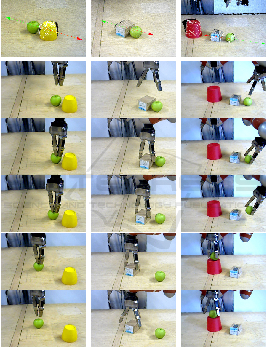
Figure 11: Execution results of three different scenarios: “pushing” (left), “pick and place” (middle), and “put on top” (right).
The top row shows the results of the geometrical reasoning. The allowed direction is marked with a green arrow, the forbidden
one with a red arrow. The full scene is also shown in the video attachment of the paper.
Context Dependent Action Affordances and their Execution using an Ontology of Actions and 3D Geometric Reasoning
227
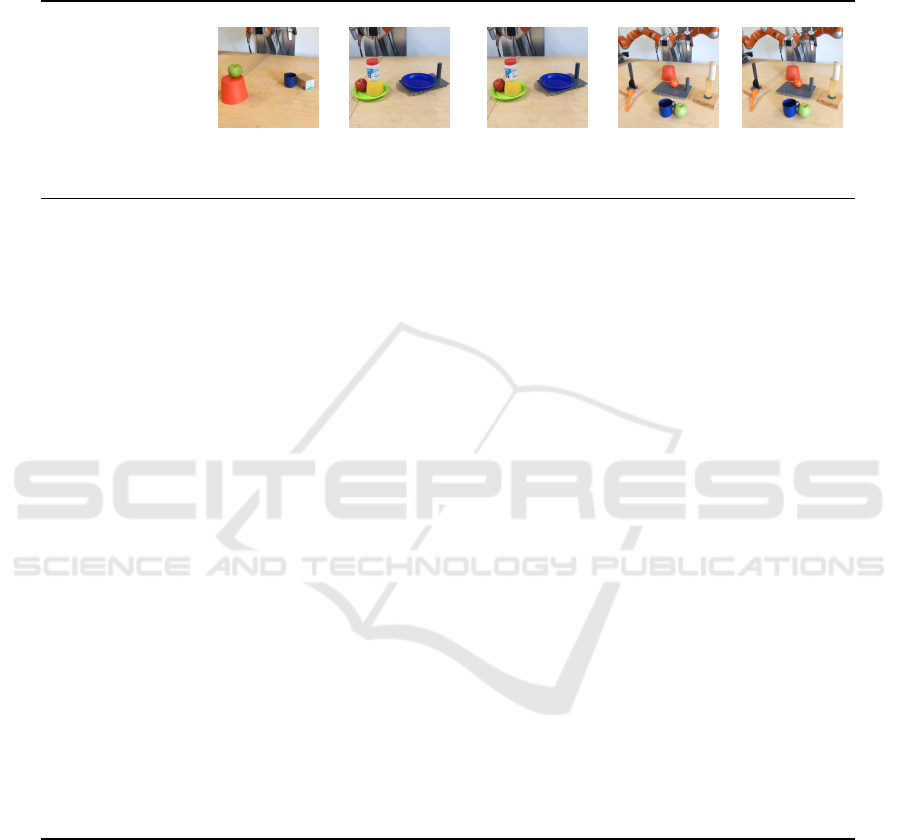
Table 2: Results of the action affordances for different scenes and objects. The different scenes are also depicted in Fig. 7.
Objects corresponding to the computed affordances are listed below the table heading. Please note that we cannot check the
preconditions for some actions, e.g. stirring, knead which are related to the material of objects. These actions are denoted
with “n”; they require high level object knowledge. For example you need a liquid and a container object for stirring. This
knowledge is not provided in the SEC domain. A “X” denotes the successful execution of the action; the actions “-” were
correctly computed as not possible to execute.
Scene 1 Scene 2 Scene 2 Scene 3 Scene 3
Main Object cup apple yellow pedestal orange apple
Primary Object box yellow pedestal green plate board cup
Secondary Object red pedestal blue plate blue plate cup board
1 punch X X X X X
2 flick X X X X X
3 poke X X X X X
4 chop - - - X -
5 bore X X X X X
6 cut - - - X -
7 scratch X X X X X
8 scissor-cut - - - X -
9 squash X X - X X
10 draw X X X X X
11 push X X - X X
12 stir n n n n n
13 knead X X - X X
14 rub X X X X X
15 lever n n n n n
16 scoop X X - X X
17 take down - - - X -
18 push down - - - X -
19 rip off - - - X -
20 break off n n n n n
21
uncover by
n n n n n
pick&place
22
uncover by
n n n n n
pushing
23 put on top - X - X -
24 push on top - - - - -
25 put over n n n n n
26 push over n n n n n
27 grasp X X - X X
28 push apart X X - - X
29 push together - - - - -
REFERENCES
Aein, M. J., Aksoy, E. E., Tamosiunaite, M., Papon, J., Ude,
A., and W
¨
org
¨
otter, F. (2013). Toward a library of ma-
nipulation actions based on semantic object-action re-
lations. In IEEE/RSJ International Conference on In-
telligent Robots and Systemsn.
Aksoy, E. E., Abramov, A., D
¨
orr, J., Kejun, N., Dellen, B.,
and W
¨
org
¨
otter, F. (2011). Learning the semantics of
object-action relations by observation. The Internati-
onal Journal of Robotics Research, 30:1229–1249.
Jamali, N., Kormushev, P., and Caldwell, D. G. (2014).
Robot-object contact perception using symbolic tem-
poral pattern learning. In IEEE International Con-
ference on Robotics and Automation (ICRA), pages
6542–6548.
Jamali, N., Kormushev, P., Vias, A. C., Carreras, M.,
and Caldwell, D. G. (2015). Underwater robot-
object contact perception using machine learning on
force/torque sensor feedback. In IEEE International
VISAPP 2018 - International Conference on Computer Vision Theory and Applications
228

Conference on Robotics and Automation (ICRA), pa-
ges 3915–3920.
Konidaris, G., Kaelbling, L. P., and Lozano-Perez, T.
(2014). Constructing symbolic representations for
high-level planning. In AAAI, pages 1932–1938.
Liang, Y.-M., Shih, S.-W., Shih, S.-W., Liao, H.-Y., and Lin,
C.-C. (2009). Learning atomic human actions using
variable-length markov models. IEEE Transactions
on Systems, Man, and Cybernetics, Part B: Cyberne-
tics, 39(1):268–280.
Papon, J., Kulvicius, T., Aksoy, E. E., and W
¨
org
¨
otter, F.
(2013). Point cloud video object segmentation using
a persistent supervoxel world-model. In IEEE/RSJ In-
ternational Conference on Intelligent Robots and Sys-
tems (IROS), pages 3712–3718.
Paul, R., Arkin, J., Roy, N., and Howard, T. M. (2016). Effi-
cient grounding of abstract spatial concepts for natural
language interaction with robot manipulators. In Ro-
botics: Science and Systems.
Rosman, B. and Ramamoorthy, S. (2011). Learning spa-
tial relationships between objects. The International
Journal of Robotics Research, 30(11):1328–1342.
Schoeler, M., Stein, S., Papon, J., Abramov, A., and
W
¨
org
¨
otter, F. (2014). Fast self-supervised on-line trai-
ning for object recognition specifically for robotic ap-
plications. In International Conference on Computer
Vision Theory and Applications (VISAPP).
Sjoo, K. and Jensfelt, P. (2011). Learning spatial relati-
ons from functional simulation. In IEEE/RSJ Interna-
tional Conference on Intelligent Robots and Systems
(IROS), pages 1513–1519.
Stein, S. C., Schoeler, M., Papon, J., and Worgotter, F.
(2014). Object partitioning using local convexity. In
IEEE Conference on Computer Vision and Pattern Re-
cognition (CVPR), pages 304–311.
W
¨
org
¨
otter, F., Aksoy, E. E., Kr
¨
uger, N., Piater, J., Ude, A.,
and Tamosiunaite, M. (2012). A simple ontology of
manipulation actions based on hand-object relations.
IEEE Transactions on Autonomous Mental Develop-
ment.
Yamane, K., Yamaguchi, Y., and Nakamura, Y. (2011). Hu-
man motion database with a binary tree and node tran-
sition graphs. Autonomous Robots, 30(1):87–98.
Context Dependent Action Affordances and their Execution using an Ontology of Actions and 3D Geometric Reasoning
229
