
New Error Measures for Evaluating Algorithms that Estimate the
Motion of a Range Camera
Boris Bogaerts
1
, Rudi Penne
1,2
, Bart Ribbens
1,3
, Seppe Sels
1
and Steve Vanlanduit
1
1
Faculty of Applied Engineering, University of Antwerp, Groenenborgerlaan 171, B-2020 Antwerp, Belgium
2
Department of Mathematics, University of Antwerp, Middelheimlaan 1, B-2020, Antwerp, Belgium
3
Multimedia and Communication Technology, Karel de Grote University College,
Salesianenlaan 90, B-2660 Antwerp, Belgium
Keywords:
Range Camera, Extrinsic Calibration, Motion Estimation, Conjugacy Invariants.
Abstract:
We compare the classical point-based algorithms for the extrinsic calibration of a range camera to the recent
plane-based method. This method does not require any feature detection, and appears to perform well using
a small number of planes (minimally 3). In order to evaluate the accuracy of the computed rigid motion
we propose two new error metrics that get direct access to the ground truth provided by a mechanism with
reliable motion control. Furthermore, these error metrics do not depend on an additional hand-eye calibration
between the mechanism and the sensor. By means of our objective measures, we demonstrate that the plane-
based method outperforms the point-based methods that operate on 3-D or 2-D point correspondences. In our
experiments we used two types of TOF cameras attached to a robot arm, but our evaluation tool applies to
other sensors and moving systems.
1 INTRODUCTION
The resolution of most Time-of-Flight (TOF) cameras
remains low compared to the resolution of common
RGB cameras (Hansard et al., 2012). This drawback
is an obstacle in the detection of point features, which
is a bottleneck in many procedures for intrinsic and
extrinsic calibration. On the other hand, range cam-
eras provide spatial reconstruction without the need
to detect point features. Recent publications demon-
strate the advantage of using planes instead of points
in the observed scene (Teichman et al., 2013; Penne
et al., 2015b; Penne et al., 2015a; Fern
´
andez-Moral
et al., 2014). Indeed, planes can be segmented easier
than corners can be detected (Fern
´
andez-Moral et al.,
2014; Penne et al., 2013; Pathak et al., 2010) and they
can be reconstructed using robust plane fitters (Torr
and Zisserman, 2000).
In this paper we focus on the qualitity of algo-
rithms for the extrinsic calibration of range cameras,
that is, for estimating the rigid transformation be-
tween two camera poses given the images of a com-
mon scene that are taken from these two poses. We
compare three esentially different strategies for ob-
taining this extrinsic calibration. In the first place,
because we use a range sensor, a 3-D point cloud is
given in the reference system of both camera poses.
If in addition to the detection of the points in both im-
ages also the correspondence between these point im-
ages is established, the rigid transformation between
these poses can be computed by standard methods as
reported in (Eggert et al., 1997) for instance. If the
3-D point clouds in the two camera reference systems
are given without correspondences, an iterative clos-
est point algorithm can be applied (as coined in (Besl
and McKay, 1992)), at the cost of accuracy (Bellekens
et al., 2015). On the other hand, a TOF camera (the
range sensor that is used in our experiments) also pro-
vides a 2-D intensity image. If planar calibration pat-
terns such as checker boards are viewed by both cam-
era poses, the transformation of these boards relative
to each camera pose can be computed by classical
calibration procedures (Zhang, 2000; Zhang, 1989).
Consequently, this yields the relative rigid transfor-
mation between both camera poses. Last but not least,
the arguments listed in the previous paragraph suggest
to use flat objects (planes) rather than points. As a
matter of fact, this option is preferred in several pub-
lications, e.g. in the extrinsic calibration procedure
of (Fern
´
andez-Moral et al., 2014) or in the registra-
tion algorithm of (Pathak et al., 2010). In Section 2.3,
we describe and explain this plane-based method via
508
Bogaerts, B., Penne, R., Ribbens, B., Sels, S. and Vanlanduit, S.
New Error Measures for Evaluating Algorithms that Estimate the Motion of a Range Camera.
DOI: 10.5220/0006510005080515
In Proceedings of the 13th International Joint Conference on Computer Vision, Imaging and Computer Graphics Theory and Applications (VISIGRAPP 2018) - Volume 5: VISAPP, pages
508-515
ISBN: 978-989-758-290-5
Copyright © 2018 by SCITEPRESS – Science and Technology Publications, Lda. All rights reserved
an elementary route, using the dual projective trans-
formation (in the same spirit as (Vasconcelos et al.,
2012; Raposo et al., 2013)). Other remarkable meth-
ods for extrinsic calibration that offer alternatives to
point measurements can be found in (Guan et al.,
2015) (for RGB-cameras, by means of spheres) or in
(Sabata and Aggarwal, 1991) (for range sensors, us-
ing lines or surfaces). But for reasons listed above,
we prefer a motion-from-planes approach.
The first contribution of this paper is to prove
that the computation of the rigid motion between two
poses of a TOF camera is more acurate and more ro-
bust when the range data is used, rather than the lumi-
nance data. Although this conclusion could have been
predicted, it is comforting to confirm it by a scientific
procedure, because the sources and the propagation
of errors are not the same for the 2D-sensor as for
the range sensor. In addition, we will conclude that
the estimated motion computed by the plane-based
method is more accurate than the point-based method
(Section 5), even when only a few planes are available
in the common view area (three, at most four). For
this comparative study we used an implementation of
the SVD algorithm of (Arun et al., 1987) for the 3-
D point-based method, an implementation of (Zhang,
1989) for the 2-D point-based method and in essence
the algorithm of (Fern
´
andez-Moral et al., 2014) for
the 3-D plane-based method.
The second (and to our opinion the most impor-
tant) contribution of this paper is the proposal of a
new type of error measures that directly referr to an
absolute ground truth for the estimated rigid motion.
So far, research articles evaluated the computed ex-
trinsic calibration indirectly because the ground truth
for camera motion seemed inaccessible. Common
performance measures for extrinsic calibration in the
absence of ground truth are the triangulation error, the
projection error or the reprojection error (Guan et al.,
2015). Unfortunately, these error measures need data
consisting of points and hence are not suitable to val-
idate a plane-based method. Futhermore, they im-
plicitely evaluate the intrinsic calibration of the used
camera(s) as well. Sometimes, the rigid transfor-
mation supplied by a state-of-the-art method such as
(Tsai, 1992) is used as ground truth, e.g. in (Guan
et al., 2016), which cannot be considered as absolute
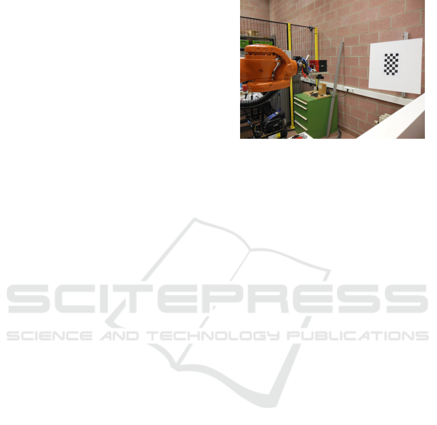
reference either. In our experiments, the TOF camera
was rigidly attached to a robot manipulator (Fig. 1).
The motion of the robot’s end effector can be consid-
ered as a very accurate ground truth.
However, it is a challenge to have access to this
ground truth data, because of the famous hand-eye
calibration problem (Shah et al., 2012). This prob-
lem is caused by the fact that the relative motion be-
Figure 1: We controlled the motion of a TOF camera by
attaching it to an articulated robotarm.
tween two positions of the camera is known in the
robot basis instead of the camera basis. The trans-
formation matrix between both reference frames, one
at the camera center and the other at the robot tool
center, is an obstacle to get access to the ground truth
provided by the robot motion. We can solve for this
transformation matrix by doing the hand-eye calibra-
tion (Mao et al., 2010; Shah et al., 2012), but this is
based on the availability of a reliable camera transfor-
mation. Therefore, using the hand-eye calibration for
evaluating the extrinsic calibration (camera motion)
gives rise to a conceptual loop, and hence is not de-
sirable. Therefore, we propose to use algebraic con-
jugacy invariants, and introduce two new error met-
rics. A major drawback of our approach is the lack
of physical interpretation of these error measures be-
cause they have an algebraic rather than a geometric
nature. However, they provide a correct scale to com-
pare different methods. As a matter of fact, it can be
used to compare all algorithms for extrinsic calibra-
tion, as long as the involved sensor can be attached to
mechanism with precisely controllable motions. The
reason why we develop more than one error metric
is the fact that there does not exist a standard proce-
dure yet to validate camera motion by means of robot
motion. Fortunately, the results by both metrics cor-
relate, providing convincing proof for the ranking of
the three considered methods.
The paper is organized as follows. In Section 2
we give an overview of the three methods that we
will evaluate for estimating the rigid motion of a TOF
camera. In Section 3 we explain our error metrics for
validating the computed camera motion by means of
the given robot motions, taking into account that the
hand-eye transformation X is unknown to us. Sec-
tion 4 describes the details of the setup of the experi-
ments. Section 5 contains the results of the evaluation
of the three compared methods, for two types of TOF
cameras, by means of the proposed error metrics.
New Error Measures for Evaluating Algorithms that Estimate the Motion of a Range Camera
509

2 RIGID CAMERA MOTION:
DESCRIPTION OF THREE
METHODS
A common way to describe mathematically the rigid
motion of a TOF camera or any other 3-D object is by
means of the coordinate transformation between the
two positions of a rigidly attached reference frame
before and after the motion. The rotational part of
the rigid motion is represented by a 3 × 3 orthonor-
mal matrix R (R
−1
= R
T
), and the translation part by
a 3 × 1 vector t. If p and p
0
are the 3 × 1 coordi-
nate vectors of a given spatial point w.r.t. the rigidly
attached reference frame before and after the motion
respectively, then
p = R · p
0
+t. (1)
Often, it is convenient to represent this transformation
by one matrix multiplication p = B · p
0
, using homo-
geneous coordinates p = (p
T
,1)
T
with weight 1, and
a 4 × 4 transformation matrix
B =
R t
0
T
1
(2)
with 0 the 3 × 1 zero vector.
In this section we exhibit three essentially differ-
ent methods for estimating the rigid motion of a TOF
camera.
2.1 2-D Extrinsic Calibration
In the first method we do not use the depth measure-
ments of the involved range sensor, but only its lumi-
nance image (2-D intensity image). Estimating the
motion between two camera positions is equivalent
to a stereo calibration from two 2-D-images, and can
be done by proven procedures, e.g. as described in
(Zhang, 1989). In our experiments, we carefully ac-
complished a lateral calibration of the TOF camera,
that is, we determined the intrinsic pinhole parame-
ters and removed non-linear lens distortion in a pre-
processing step.
Next, for each camera position we computed the
4 × 4 rigid transformation matrix H with respect to a
fixed calibration checkerboard with known size (Sec-
tion 4). Finally, the extrinsic transformations H
1
and
H
2
of both camera positions relative to the fixed cal-
ibration pattern yield the rigid transformation B =
H
−1
2
· H
1
of the camera.
2.2 3-D Point Measurements
Given a set of corresponding 3-D points,
p
1
,..., p
N
←→ p
0
1
,..., p
0
N
(3)
there are several methods to estimate the rigid trans-
formation (R,t) mapping the first set to the second. A
comparison between different methods is presented in
the review paper (Eggert et al., 1997). The determi-
nation of the most likely translation t and rotation R
comes down to finding the least-squares solution of a
system of 3N linear equations caused by N pairs of
corresponding 3-D points, where each pair yields 3
equations as given by Eqn. 1. Equivalently, the mo-
tion pair (R,t) is determined by minimizing the sum
of squares error:
SSE =
N
∑
i=1
||p
i
− Rp
0
i
−t||
2
(4)
subject to the constraint that R has to be orthonormal.
In our experiments we followed the method of (Arun
et al., 1987), that computes the rotation and transla-
tion separately. As a first step this centroid is calcu-
lated both before and after transformation, p
c
and p
0
c
,
such that both point clouds can be presented relative
to their centroid: p
ci
= p
i
− p
c
and p
0
ci
= p
0
i
− p
0
c
. In
(Arun et al., 1987) it is proved that the rotation matrix
R that minimizes SSE is given by
R = VU
T
, (5)
where the matrices V and U are found by the singular
value decomposition H = UΛV
T
of
H =
N
∑
i=1
p
0
ci
p
T
ci
. (6)
Finally, the translation part is estimated by means of
both centroids: t = p
c
− p
0
c
.
2.3 3-D Plane Measurements
If the rigid transformation of a depth camera is rep-
resented by a 4 by 4 transformation matrix B acting
on homogeneous coordinates of 3-D points as given
by Eqn. 2, then the corresponding dual transformation
acting on plane coordinates (a, b,c,d)
T
is represented
by B
−T
(Pottmann and Wallner, 2001):
a
b
c
d
∼ B
−T
a
0
b
0
c
0
d
0
⇔
a
0
b
0
c
0
d
0
∼ B
T
a
b
c
d
(7)
Because the homogeneous plane coordinates
(a,b,c,d)
T
are determined up to a scale factor,
it is convenient to normalize the plane normals
n = (a,b,c)
T
to length 1. This leaves us with one
more ambiguity, due to the two opposite directions
for n. This can be resolved by some additional
constraint, e.g. requiring that all plane normals point
VISAPP 2018 - International Conference on Computer Vision Theory and Applications
510

towards the 3D sensor. With these conventions the
proportional similarity of Eqn. 7 can be replaced by
an equality. Consequently, the rigid motion (R,t) of
the camera transforms the plane coordinates (n
T
,d)
T
for k considered planes as follows:
n
0
1
··· n
0
k
d
0
1
... d
0
k
=
R
T
0
t
T
1
n
1
··· n
k
d
1
... d
k
=
R
T
n
1
··· R
T
n
k
t
T
· n
1
+ d
1
... t
T
· n
k
+ d
k
(8)
These equations can be decoupled into a system for R
and a system of t. Furthermore, the equations for R
make only use of the plane normals:
(n
0
1
... n
0
p
) = R
T
(n
1
... n
p
)
(d
0
1
... d
0
p
) = t
T
(n
1
... n
p
) + (d
1
... d
p
)
(9)
So, the rotational part of the desired rigid motion can
be estimated by minimizing
SSE =
p
∑
i=1
||n
i
− Rn
0
i
||
2
(10)
in the same spirit of (Arun et al., 1987). This is equiv-
alent to maximizing trace(RH), where H is the 3 × 3
matrix defined by
H =
p
∑
i=1
n
0
i
n
T
i
, (11)
which is accomplished once again by the SVD H =
UΛV
T
and putting R = VU
T
. On the other hand, the
translational part t can be estimated by a least squares
solution for the equations containing t in the system
of Eqn. 9.
3 ERROR METRICS
3.1 The Charpoly Error Metric
In our experiments we have used two error metrics in
order to evaluate the accuracy of different methods for
estimating the rigid camera motion. The validation is
done by means of the known motion of an articulated
robot arm where the camera was rigidly attached to
(Fig. 1). Therefore, we introduce error metrics that
leverage the fact that the camera motion is conjugated
to the known robot motion. This means that the mo-
tion is the same, but expressed in different bases. If
the 4 × 4 transformation matrix A denotes the motion
of the robot, and if B represents the camera motion
matrix, then this conjugacy is algebraically expressed
by similarity of matrices (Hoffman and Kunze, 1971):
A = XBX
−1
(12)
In the literature this issue is also known as the AX =
XB calibration problem (Mao et al., 2010). This 4 × 4
matrix X is the so-called hand-eye calibration be-
tween robot and camera. In general, the transforma-
tion X between the robot coordinate frame and the
camera frame is not a priori known. In our validation
experiments, the robot transformation A is accurately
known and considered as ground truth, while the esti-
mation of B using different algorithms has to be vali-
dated.
In order to validate B by means of A we can use
conjugacy invariants. It is a fundamental algebraic
property that similar matrices have the same charac-
teristic polynomial (Hoffman and Kunze, 1971):
p(λ) = det(A − I
4
λ) = det(B − I
4
λ) (13)
Each coefficient of this characteristic polynomials can
serve to evaluate camera motion matrices against the
known robotic motion matrices. In theory these coef-
ficients are identical. A 4 × 4 transformation matrix
has a characteristic polynomial of degree 4 with five
coefficients:
p(λ) =λ
4
+ (tr(R) − 1)λ
3
− (tr(R) + k)λ
2
+ (k − det (R))λ + det(R)
(14)
Analyzing the calculation of the characteristic equa-
tion of a rigid transformation matrix reveals that two
parameters determine all the coefficients. The first
parameter is the trace of the rotational part R of the
transformation matrix. The second parameter (k) is a
bit more complicated:
k = r
11
r
22
+ r
11
r
33
+ r
22
r
33
+ r
31
r
13
+ r
23
r
32
+ r
12
r
21
(15)
This parameter k and the trace of the rotational part
are the two components that compose the first error
metric that we suggest, the charpoly error metric. No-
tice that this error metric only provides a quality eval-
uation for the rotational part of the calculated trans-
formation matrix.
CPE
tr
= tr(R
A
) − tr(R
B
) (16)
CPE
k
= k
A
− k
B
(17)
These two parameters will be kept separate because
it is not immediately obvious how to combine them
into one parameter that describes the global similarity
between matrices A and B.
3.2 The Hand-eye Error Metric
The second error metric that we propose is less
straightforward. In this metric different measure-
ments associated with several camera transformations
New Error Measures for Evaluating Algorithms that Estimate the Motion of a Range Camera
511

will be combined in a system of equations that could
be used to compute the hand-eye calibration X:
AX −XB = 0 (18)
These matrices are all 4 × 4 transformation matrices
and can be expressed as block matrices:
R
A
t
A
0
T
1
R
X
t
X
0
T
1
=
R
X
t
X
0
T
1
R
B
t
B
0
T
1
.
(19)
Or, after performing the matrix multiplications:
R
A
R
X
R
A
t
X
+t
A
0
T
1
=
R
X
R
B
R
X
t
B
+t
X
0
T
1
.
(20)
Using the tensor product ⊗ of matrices and the vec-
torizationvec(Q) denotes of matrix Q, we obtain a
system of 12 linear equations in the 9 unknowns
(vec(R
X
)
T
,t
T
X
) (Petersen and Pedersen, 2012):
I
3
⊗ R
A
− R
T
B
⊗ I
3
0
t
T
B
⊗ I
3
I
3
− R
A
| {z }
M
vec(R
X
)
t
X
=
0
t
A
| {z }
s
(21)
Eqn. 21 was mentioned in the review paper (Shah
et al., 2012) on hand-eye calibration. In order to de-
termine (R
X
,t
X
) we need to know the robot motion A
and the corresponding measured camera transforma-
tion B. To actually solve this system, at least three
given transformation pairs (A,B) are necessary. In
practice, coping with noisy measurements, we com-
bine Eqn. 21 for multiple transformation pairs (n ≥ 3)
as follows:
M
1
.
.
.
M
n
vec(R
X
)
t
X
=
s
1
.
.
.
s
n
(22)
Now we introduce our second error metric, as a qual-
ity measure of the system in Eqn. 22. It is the mean
residue for the least squares solution to the transfor-
mation X:
HEE =
q
||s − M(M
T
M)
−1
M
T
s||
2
/(12n) (23)
with M = (M
T
1
,...,M
T
n
)
T
and s = (s
T
1
,...,s
T
n
)
T
. We
refer to this error metric with the acronym HEE
(hand-eye-error). The error metric provided by Eqn.
23 is motivated by the following arguments:
• The robot transformation A is known accurately.
• The transformation matrix X necessarily exists
and is fixed for a given robot-sensor system.
Therefore HEE would be 0 if the rigid motion B
of the depth sensor was computed correctly (as-
suming zero noise for A).
• HEE is able to assess the validity of a method
over multiple measurements, yielding a growing
system of equations (Eqn. 22). Therefore, it also
evaluates the stability of a proposed method.
4 EXPERIMENTAL SETUP
The objective of our experiments is to evaluate the ac-
curacy of three different methods for computing the
rigid motion of a TOF camera. All the tests have
been repeated for two common Time-of-Flight cam-
eras: Kinect V2 and Mesa SR4000. In order to com-
pare the computed motion to a reliable ground truth,
the Time-of-Flight sensors are mounted rigidly on an
articulated robotarm (KUKA KR16, with a repeatibil-
ity error less than 0.1mm). See Fig. 1. In each single
test we consider TOF images for a pair of robot posi-
tions, in which the attached camera observes a classi-
cal calibration checkerboard. During the whole exper-
iment we arranged 6 distinct positions of this checker-
board, that could be viewed from 20 pre-programmed
robot configurations, providing a supply of 6 ×
20
2
test pairs for each camera.
The detection of the checker corners is performed
in the luminance images of the TOF cameras. For
the 2-D extrinsic calibration we used an implemen-
tation of (Zhang, 2000), combined with a nonlinear
optimization to minimize the reprojection error.
For the second and third method we needed a
set of 3-D points, generated by both used types of
TOF sensors, directly provided in (X,Y, Z) coordi-
nates with respect to the camera frame. This means
that we assumed a priori calibrated TOF cameras. The
3-D point-based method makes use of pairs of corre-
sponding points in both range sensors. Because TOF
cameras deliver poor depth measurement accuracy at
the detected checker corners due to the black-white
transitions (Pattinson, 2011; Fuchs and May, 2008),
we preferred to reconstruct the centers of the white
checkerboard. These centers can be found by inter-
secting the diagonals of the checker squares. Note
however that these square centers (nor the checker
corners) are likely to coincide with a pixel, causing
additional round off errors for the depth measure-
ments.
The third method, based on plane measurements,
is by far the most user friendly one. Here there is no
need for performing feature detection and find point
correspondences. We only reconstruct points on the
plane supporting the checker board. To this end we
automatically selected the pixels in the white check-
ers and on the larger panel that the calibration board
had been attached to. The 3-D measurements are di-
rectly available in these pixels, avoiding depth inter-
polation. Furthermore, depth measurements for white
pixels are known to be more accurate than for black
pixels (Pattinson, 2011; Fuchs and May, 2008). Next,
we compute the best-fitting plane supporting the re-
constructed 3-D points in each of both given range im-
VISAPP 2018 - International Conference on Computer Vision Theory and Applications
512

ages of a fixed calibration board. Working with these
plane coordinates flattens error fluctuations for the 3-
D point measurements, and moreover avoids the task
to detect features and to establish correspondences.
This best-fitting plane can be computed by principal
component analysis, but we prefer a more robust es-
timate based on Ransac (Fischler and Bolles, 1981).
More precisely, we applied an implementation of the
algorithm of (Torr and Zisserman, 2000).
5 RESULTS
For the sake of validation, random transformations are
sampled from our dataset. This dataset consists of
measurements from 20 different robot positions (Sec-
tion 4). In each such position, 6 images have been
taken by a TOF sensor that was rigidly attached to
the articulated robot arm. These TOF images con-
tain both 2-D intensity images and depth measure-
ments of the 6 fixed spatial positions of a calibration
checkerboard. Finally, all these measurements have
been repeated for two different commonly used Time-
of-Flight cameras: Kinect V2 and Mesa SR4000. For
the three methods that we intend to evaluate, the rigid
camera motion is estimated for some randomly se-
lected pairs of robot positions. The three algorithms
always operate on the same pairs of robot positions
for the sake of comparison.
1. For the first method, the extrinsic calibration
based on the 2-D luminance images, we use one
randomly selected calibration plane image, the
same for both robot positions. The checker cor-
ners are detected at subpixel level, the correspon-
dence is established in the pair of 2-D images, and
the relative transformation between both camera
poses is estimated via two extrinsic calibrations
relative to the calibration plane position.
2. If the rigid transformation is estimated by means
of 3-D point correspondences, the same calibra-
tion plane is used. The depth images enable spa-
tial recoveries of the white square midpoints (in-
tersection of the diagonals), providing a corre-
sponding pair of 3-D point sets.
3. In case we compute the rigid camera motion (R,t)
by means of planes as a solution of the system
given by Eqn. 9, some fixed number of planes are
randomly selected from the 6 available calibration
boards. A solution of the system given by Eqn. 9
is determined if at least three planes with linearly
independent normals are available.
5.1 Evaluation by Means of the
Charpoly Error Metric
In our experiment a large amount of transformations
are sampled from the total set of possible transforma-
tions in the constructed dataset. The calculated trans-
formations are compared to the ground truth robot
motion. To accomplish this goal we can use the al-
gebraic conjugacy invariants of Section 3.1. The ab-
solute difference between both traces of the rotational
part and the defined k value are stored. To evaluate
the quality of the rotational part of the obtained trans-
formation the distributions of the charpoly error met-
ric are visualized using boxplots (Fig. 2). For both
cameras we observe that the two conjugacy invari-
ants constituting the charpoly error metric (trace and
k) agree in their evaluation.
M K M K M K M K
0
0.02
0.04
0.06
0.08
0.1
0.12
absolute difference of trace
Trace
M K M K M K M K
0
0.05
0.1
0.15
0.2
0.25
0.3
absolute difference of k
k
planes (4)
planes (3) 3D-points
luminance
planes (4)
planes (3)
3D-points
luminance
Figure 2: The quality of the rotation between two positions
of TOF camera is compared for the three described meth-
ods. The plane-based method was done for 3 and for 4
planes. The two parameters of the charpoly error metric
are evaluated for the Kinect V2 (K) and the Mesa SR4000
(M).
The quality of the estimated rotation as obtained
by the plane-based method is similar to the rotation
as obtained by 3-D points, as far as the charpoly error
metric is concerned (Fig. 2). Next, it is striking that
the 3-D methods (operating on range data) compute
the camera rotation with a lower median error value
and smaller spread than the 2-D method (operating
on luminance images). So, it appears that the 2-D
method for extrinsic calibration of a 3-D sensor is less
accurate and less robust.
We also observe that the plane method performs
very well even when using the required minimum of
3 planes, and only slighty better when using 4 planes.
Our experiments demonstrate that using more redun-
dancy (5 or 6 planes) does not imply a better quality of
the estimated transformation. The empirical fact that
estimating a camera motion by means of 3 or 4 planes
is at least as good as by means of 20 correspondence
pairs of 3-D points, and definitely better than by 2-D
extrinsic calibration, can be explained by the fact that
New Error Measures for Evaluating Algorithms that Estimate the Motion of a Range Camera
513
the involved plane normals are very reliable. They are
obtained by a robust plane fitter, averaging out occur-
ing depth noise.
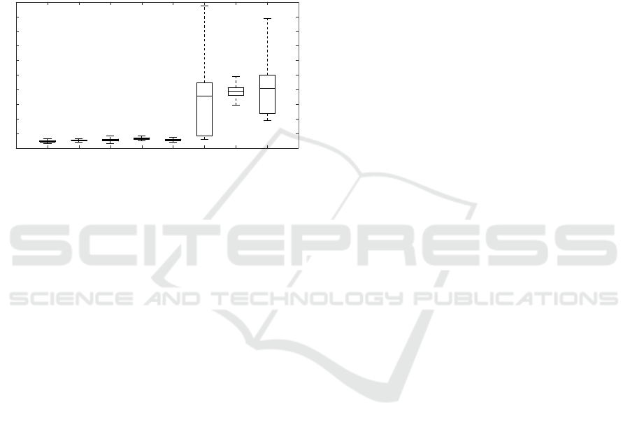
5.2 Evaluation by Means of the
Hand-eye Error Metric
In this validation a fixed number of transformations
(pairs of robot positions) were sampled for each hand-
eye calibration system size.
M K M K M K M K
0
5
10
15
20
25
30
35
40
45
50
HEE
luminance
3D-points
planes (3)
planes (4)
Figure 3: A boxplot visualizing the distribution of the hand-
eye error for the evaluated methods, for the Mesa SR4000
(M) and for the Kinect V2 (K). Methods with a very broad
distribution are unstable and thus unreliable.
During the experiment it turned out that the mag-
nitude of the hand-eye error strongly depends on
the selected transformation. However, this ‘instabil-
ity problem’ was not observed for the plane-based
method, for none of the used cameras (Fig. 3). The
evaluation by the hand-eye error metric implies that
the point-based methods are inherently too incon-
sistent to compute the hand-eye calibration between
robot and camera, while the plane-based method ap-
pears to be able to estimate a hand-eye transforma-
tion in a consistent way, independent of the consid-
ered robot configurations. The inferior result of the
3-D point method for the Kinect camera can be ex-
plained by its larger field of view compared to that
of the Mesa camera. Consequently, the working dis-
tance of the Kinect is larger, and therefore the image
size of the checkerboard is smaller than observed by
the Mesa. This results in a bigger round of error in
the point matching. This inherent drawback for the
3-D point method is circumvented by the 3-D plane
method.
6 CONCLUSIONS
We investigated the quality of several methods for
computating of the rigid motion of a TOF camera. We
evaluated the classical 2-D stereovision approach, us-
ing only the luminance images of the TOF camera,
and two 3-D methods that take benefit from the range
data. The 3-D points method needs corner detection
and point correspondences, while for the 3-D planes
method we only have to randomly select pixels in a
segmented region. In our experiments we considered
the motion of a computer driven robot arm as ground
truth. In order to have access to this ground truth and
to get around the unknown hand-eye transformation,
we designed two error metrics, being algebraic con-
jugacy invariants. We believe that our evaluation for
extrinsic calibration methods is more appropriate than
other perfomance measures such as triangulation er-
ror or reprojection error, because we do not depend on
feature detection nor correspondence determination.
Furthermore, the ground truth provided by a robot
manipulator is more absolute and reliable compared
to a reference obtained from a state-of-the-art algo-
rithm. All our experiments, for both types of cameras
and for both proposed error measures, agreed on the
same conclusions:
• The 3-D methods for estimating the motion of a
range camera definitely outperform 2-D methods.
• The 3-D planes method appears to be more robust
and accurate than the 3-D points method.
• it appears that only a small number of planes (3
or 4) are needed to guarantee the reported for the
plane-based method.
ACKNOWLEDGEMENTS
The first author holds a PhD grant from the research
Fund-Flanders (FWO Vlaanderen).
REFERENCES
Arun, K. S., Huang, T. S., and Blostein, S. D. (1987). Least-
squares fitting of two 3-d point sets. 9(5):698–700.
Bellekens, B., Spruyt, V., Berkvens, R., Penne, R., and
Weyn, M. (2015). A benchmark survey of rigid 3d
point cloud registration algorithms. Int. J. Adv. Int.
Systems, 8(1 & 2):118–127.
Besl, P. J. and McKay, N. D. (1992). A method for registra-
tion of 3-d shapes. IEEE Trans. Pattern Anal. Mach.
Intell., 14(2):239–256.
Eggert, D., Lorusso, A., and Fisher, R. (1997). Estimating
3-d rigid body transformations: a comparison of four
major algorithms. Machine Vision and Applications,
9(5):272–290.
Fern
´
andez-Moral, E., Gonz
´
alez-Jim
´
enez, J., Rives, P., and
Ar
´
evalo, V. (2014). Extrinsic calibration of a set of
VISAPP 2018 - International Conference on Computer Vision Theory and Applications
514

range cameras in 5 seconds without pattern. In In-
ternational Conference on Intelligent Robots and Sys-
tems. IEEE/RSJ.
Fischler, M. and Bolles, R. (1981). Random sampling con-
sensus: A paradigm for model fitting with applications
to image analysis and automated cartography. Com-
munications of the ACM, 24:381–385.
Fuchs, S. and May, S. (2008). Calibration and registra-
tion for precise surface reconstruction with time of
flight cameras. Int. J. Intell. Syst. Technol. Appl.,
5(3/4):274–284.
Guan, J., Deboeverie, F., Slembrouck, M., van Haeren-
borgh, D., van Cauwelaert, D., Veelaert, P., and
Philips, W. (2015). Extrinsic calibration of cam-
era networks using a sphere. Sensors, 15(8):18985–
19005.
Guan, J., Deboeverie, F., Slembrouck, M., Van Haeren-
borgh, D., Van Cauwelaert, D., Veelaert, P., and
Philips, W. (2016). Extrinsic calibration of camera
networks based on pedestrians. Sensors, 16(5).
Hansard, M., Lee, S., Choi, O., and Horaud, R. (2012). Time
of Flight Cameras: Principles, Methods, and Applica-
tions. SpringerBriefs in Computer Science. Springer.
Hoffman, K. and Kunze, R. (1971). Linear algebra.
Prentice-Hall mathematics series. Prentice-Hall.
Mao, J., Huang, X., and Jiang, L. (2010). A flexible solu-
tion to ax=xb for robot hand-eye calibration. In Pro-
ceedings of the 10th WSEAS International Conference
on Robotics, Control and Manufacturing Technology,
ROCOM’10, pages 118–122, Stevens Point, Wiscon-
sin, USA. World Scientific and Engineering Academy
and Society (WSEAS).
Pathak, K., Birk, A., Va
ˇ
skevi
ˇ
cius, N., and Poppinga, J.
(2010). Fast registration based on noisy planes with
unknown correspondences for 3-d mapping. Trans.
Rob., 26(3):424–441.
Pattinson, T. (2011). Quantification and Description of Dis-
tance Measurement Errors of a Time-of-Flight Cam-
era. PhD thesis, University of Stuttgard.
Penne, R., Mertens, L., and Ribbens, B. (2013). Planar
segmentation by time-of-flight cameras. In Advanced
Concepts for Intelligent Vision Systems, volume 8192
of Lecture Notes in Computer Science, pages 286–
297.
Penne, R., Raposo, C., Mertens, L., Ribbens, B., and
Araujo, H. (2015a). Investigating new calibration
methods without feature detection for tof cameras. Im-
age and Vision Computing, 43:5062.
Penne, R., Ribbens, B., and Mertens, L. (2015b). An incre-
mental procedure for the lateral calibration of a time-
of-flight camera by one image of a flat surface. Inter-
national Journal of Computer Vision, 113(2):81–91.
Petersen, K. B. and Pedersen, M. S. (2012). The Matrix
Cookbook. Technical University of Denmark. Version
20121115.
Pottmann, H. and Wallner, J. (2001). Computational Line
Geometry. Springer-Verlag New York, Inc., Secaucus,
NJ, USA.
Raposo, C., Barreto, J., and Nunes, U. (2013). Fast and ac-
curate calibration of a kinect sensor. In International
Conference on 3D Vision. IEEE.
Sabata, B. and Aggarwal, J. (1991). Estimation of motion
from a pair of range images: A review. CVGIP: Image
Understanding, 54(3):309 – 324.
Shah, M., Eastman, R. D., and Hong, T. (2012). An
overview of robot-sensor calibration methods for eval-
uation of perception systems. In Proceedings of the
Workshop on Performance Metrics for Intelligent Sys-
tems, PerMIS ’12, pages 15–20, New York, NY, USA.
ACM.
Teichman, A., Miller, S., and Thrun, S. (2013). Unsuper-
vised intrinsic calibration of depth sensors via SLAM.
In Robotics: Science and Systems.
Torr, P. and Zisserman, A. (2000). Mlesac: A new robust
estimator with application to estimating image geom-
etry. Comput. Vis. Image Underst., 78(1):138–156.
Tsai, R. Y. (1992). Radiometry. chapter A Versatile Cam-
era Calibration Technique for High-accuracy 3D Ma-
chine Vision Metrology Using Off-the-shelf TV Cam-
eras and Lenses, pages 221–244. Jones and Bartlett
Publishers, Inc., USA.
Vasconcelos, F., Barreto, J., and Nunes, U. (2012). A min-
imal solution for the extrinsic calibration of a cam-
era and a laser-rangefinder. IEEE Trans Pattern Anal
Mach Intell., 34(11):2097–2107.
Zhang, Z. (1989). Motion and structure from two perspec-
tive views: algorithms, error analysis, and error esti-
mation. 11(5):451–476.
Zhang, Z. (2000). A flexible new technique for camera cal-
ibration. 22(11):1330–1334.
New Error Measures for Evaluating Algorithms that Estimate the Motion of a Range Camera
515
