
A Comprehensive Study of Sea Wave Tidal Power Plant (PLTPS)
E. Warman
1
, W. Armi
1
, and F. Fahmi
2
1
Department of Electrical Engineering, Faculty of Engineering, Universitas Sumatera Utara
2
Centre of Excellence Sustainable Energy and Biomaterial, Universitas Sumatera Utara,
Jl. Almamater, Kampus USU Medan 20155 INDONESIA
Keywords: Tidal, Sea wave, Power plant.
Abstract: The use of fossil fuel sources to power plants is a major problem in many countries in the world today. Among
power plants that use water as an energy source, tidal energy is one alternative of renewable energy sources.
This paper discusses all matters relating to tidal power plants (PLTPs) of the type, generation process,
advantages and disadvantages as well as the subject of this study discussed three case studies of generators of
two types of conversion, i.e., tidal range and tidal stream to see the characteristics of each plant. From the
result of the case study, it can be seen that the prospect of the implementation of marine energy development
especially the tidal energy is good enough to be seen from the potential of Indonesia sea that has the range
and speed of current that fulfill the provisions, especially in some straits in eastern Indonesia
.
1 INTRODUCTION
Energy use indirectly contributes to the high
concentrations of CO2 in the atmosphere that have
increased significantly over the last century. From
some sectors of energy users, the electricity and heat
generation sectors are the most widely used energy
sources so as to be directly proportional to CO2
emissions into the atmosphere as shown in Figure 1
(IEA, 2015).
Figure 1: CO
2
emissions from various sectors in 2013
The use of fossil fuel for power plant has been an
inevitable problem. Because of the negative effects
caused by the release of CO2 into the atmosphere and
the depleting supply of non-renewable sources of
energy while the use of electric energy is increasing,
then the use of renewable energy sources began to
promote.
Tidal energy is one alternative source of
renewable energy. The working principle is the same
as hydroelectricity, where water is used to rotate
turbines and generate electrical energy. Energy is
derived from the utilization of sea level variations
contained in the tidal mass transfer of water.
2 MATERIAL AND METHODS
2.1 Tidal Energy Conversion System
Tidal Barrage is a tidal utilization technology using
barrage or dam. Energy is produced from the
difference in sea tidal height. Electricity is generated
through a turbine placed at the dam.
The dam extracts tidal energy from the height
difference between water in the Dam and at sea.
When the tide, water will enter into the Dam until
certain conditions the water will be retained and
released back through the water turbine when the
water receded. From the process of tidal movement of
water that moves the turbine in the Dam then, the
electrical energy can be obtained.
280
Marwan, E., Armi, W. and Fahmi, F.
A Comprehensive Study of Sea Wave Tidal Power Plant (PLTPS).
DOI: 10.5220/0010085302800286
In Proceedings of the International Conference of Science, Technology, Engineering, Environmental and Ramification Researches (ICOSTEERR 2018) - Research in Industry 4.0, pages
280-286
ISBN: 978-989-758-449-7
Copyright
c
2020 by SCITEPRESS – Science and Technology Publications, Lda. All rights reserved
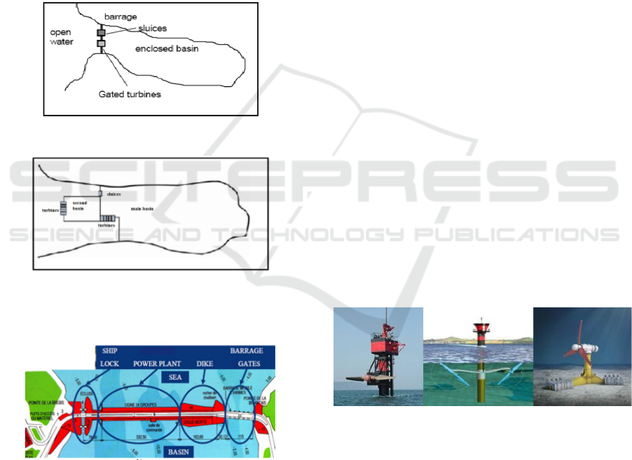
There are two main types of tidal reservoirs:
single-basin and double-basin systems. Single Basin
consists of one basin and requires a dike that cuts
down the estuary or bay. There are three operating
patterns in this system such as tidal generation, tidal
generation and two-way generation as in Figure 2.
Double Basin system requires the construction of two
barrages, core and additional. The main basin is
basically the same as the receding mode in a single
basin system. The difference is that in this case some
of the energy produced is used to pump water into the
second basin. For this reason, the second dam acts as
a storage element, extending the time period in which
the dam can generate electricity as illustrated in
Figure 3.
Figure 2: System Single Basin
Figure 3: System Double Basin
Figure 4 describes the barrage type PLTPs
component.
Figure 4: The layout of PLTPs type barrage component
Some components and its function as follows:
1. Gate: The gate controls the flow of water between
the sea and the basin.
2. Substation: Ground generator to raise the voltage
and interconnect to the network.
3. Basin: Water reservoir area at high tide and return
water to the sea at low tide (low tide).
4. Inactive dike: Separation barrier.
5. Powerhouse: Generally, power plants use bulb
turbines as their initial drivers.
6. Lock: The structure built between the sea and the
basin that allows the ship or boat to pass.
2.2 Tidal Stream
Tidal Stream or tides that is the movement of
seawater due to the tidal cycle, creating kinetic
movement. The potential of this current is usually
located near the coast; especially there is inhibiting
the topography, such as inter-island straits. Turbines
used in this technology are often called Free Flow
Tidal Turbine (FFTT), have the same form and
working principle with a wind turbine. The large
density of seawater makes the current drive strong so
that the FFTT can generate large electrical energy.
Currently, there are two types of turbines,
horizontal axis turbine, and a vertical axis turbine. In
the horizontal axis turbine (HAT), the blades are
designed in the opposite direction with the direction
of ocean currents due to the current velocity and
direction of the current causing the turbine blades to
rotate as in Figure 5. Turbine blades are below the
rotating water surface on the horizontal axis parallel
to the direction of the water flow. The optimum
operating point of this turbine is at a current velocity
between 4 and 5.5 mph (Khaligh, 20018). At the
current velocity, a 15-meter turbine is capable of
producing energy comparable to a 60-meter wind
turbine. The strategic location of power plant
placement with this type of turbine is near the coast at
a depth of 20-30 meters.
(a) (b) (c)
Figure 5: (a), (b) 2 blades; (b) 3 horizontal blades
Vertical axis turbine (VAT) is designed perpendicular
to the direction of ocean currents as shown in Figure
6. VAT has greater efficiency but is unstable, and the
resulting vibration is higher. Another advantage is
that the size of the blade on a VAT type turbine can
be increased without any restrictions as in the HAT
turbine type. Figure 7 describes the PLTPs
component of the stream type.
A Comprehensive Study of Sea Wave Tidal Power Plant (PLTPS)
281

Figure 6: (a) vertical axis turbine; (b) gorlov turbine
Figure 7: Component of PLTPs
2.3 Power on Turbine
To calculate the estimated power output of this
turbine PLTPs used the following formula:
2.3.1 PLTPs System Dams (Barrage)
The capacity of a barrage type tidal turbine can be
calculated by Equation 1 (Araquistain,-):
(1)
With: E = potential energy (J), A = the horizontal area
of the dam (m
2
), ρ = density of water (1025 kg/m
3
) /
(1021-1030 for seawater), g = the force of gravity of
the earth (9.81 m/s
2
) , h = the water level at the dam
(m).
From Equation 1, we can calculate the power which
can be generated using Equation 2:
(2)
With: P = Energy raised (W), η = turbine efficiency,
t = time of operation (s)
2.4 PLTPs Flow Tide System (Stream)
Tidal current turbine capacity can be calculated by
Equation 3 (Royal Academy of Engineering,-)
(3)
With: P = Energy raised (W), η= turbine effiency, ρ =
density of water = 1025 kg/m
3,
A = turbine
coverage area (m
2
), V= speed of water flow (m/s)
The literature review study was conducted by a
systematic search on electronic databases: Web of
Science, British Hydropower Associates (BHA),
Indonesian Energy Outlook and several other
publications. The search is then continued by
scanning a list of references from relevant
publications so that explanations of case studies can
be more widely elaborated. The aspects reviewed
include the following: location of construction,
structure, and components, tidal potential, type of
turbine, working cycle, generation capacity, and
annual energy.
The case study discussed in this paper are 3 tidal
power generation units. The three power generating
units represent two types of tidal power and tidal
current tidal ranges. The 3 units are La Rance, Sihwa,
and Strangford Narrow as shown in Table 1.
Table 1: Case studies of PLTPS
Sea
Tidal
Power
Plants
Gener
ator
Type
Generator
Name
Location
Year of
Developme
n
t
Tidal
Range
La Rance F
r
ance 1966
Sihwa
South
Korea
2010
Tidal
Curre
n
t
Strangford
Northern
Ireland
2008
3 RESULTS
3.1 La Rance Tidal Power Plant, France
La Rance Tidal Power Plant is a tidal power plant
built in the estuary of the river Rance in Brittany,
France as illustrated in Figure 8. With a capacity of
240 MW and built in 1966 making it the oldest and
second largest PLTPs in the world and generating an
annual capacity of 540 GWh (BHA, 2009). With a
tidal height of 8.2 m which is the largest tidal range
in France the plant supplies electrical energy to a 225
kV national transmission network and illuminates ±
1300,000 homes annually.
The background of the construction of PLTPs at
the mouth of this river includes the height of the
largest tidal range including in France with an
average of 8.2 m to a maximum of 13.5 m. The
reservoir volume is 184,000,000m3, with more than
20km to the headwaters (22km2 basin area) and only
750 m wide by the mouth of the estuary.
ICOSTEERR 2018 - International Conference of Science, Technology, Engineering, Environmental and Ramification Researches
282
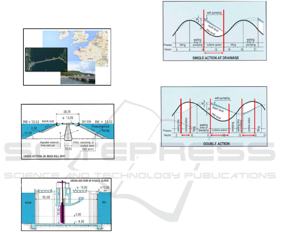
a. Structure and Components
1. Powerhouse
Bulb turbines are placed on a 332.5m powerhouse
dam.
2. Dam
Dyke or embankment on La Rance power plant has a
length of 163.6m. with a barrage length of 145.1 m, 6
gates or a water gate with a height of 10 m, a width of
15 m and a maximum water flow of 9600 m
3
/s with a
basin area of 22 km
2
as illustrated in Figures 9 and 10.
Figure 8: Location La Rance tidal power plant
Figure 9: Construction dyke at La Rance tidal power plant
Figure 10: Construction Barrage at La Rance
b. Electric Supplies
In the La Rance tidal power plant, there are 24 x 10
MVA alternators operating in 2bar (28.44psi)
pressurized air absolute pressing; AI 3.5kV. There are
6 units of operation with each 4 bulb turbine complete
with supporting components for turbine and
alternator adjustment. 3 transformer units (3.5 / 3.5 /
225kV) with 80MVA power, with OFAF cooling
system and 225kV network connection using oil-
filled cables under pressure.
c. Working Cycle
The work cycle on the La Rance tidal power plant is
shown in Figures 11 and 12.
1-way generation (Tidal generation)
2-way generation (Tidal generation and
generation on the rising tides)
Figure 11: A 1-way work cycle at La Rance tidal power
plant
Figure 12: A 2-way work cycle at La Rance tidal
d. Turbine
The characteristics of turbine bulb used in La Rance
PLTPs are 5.35 m diameter, weight: 470 t, Rated head
5.65 m, discharge at rated head 275 m
3
/s, output 10
MW, rotation speed 93.75 rpm, max. over speed: 260
rpm, 4 blades (inclination: -5° to +35°), 24 guide
vanes, minimum head: 3 m and maximum head: 11
m.
3.2 Sihwa Tidal Power Station, South
Korea
Sihwa Lake Tidal power station is located 4 km from
Siheung town in Gyeonggi Province South Korea As
illustrated in Figure 14. With a capacity of 254 MW
makes the Power plant is the largest PLTPs today.
Power is generated by utilizing the rising tidal flow
into a 30 km
2
basin using 10 turbine bulb units of 25.4
MW capacity. 8 water gates placed to release water
from the barrage to the sea. This project cost $ 355.1m
and was built between 2003 and 2010 generating an
annual capacity of 552.7 GWh (Schneeberger, 2008).
A Comprehensive Study of Sea Wave Tidal Power Plant (PLTPS)
283
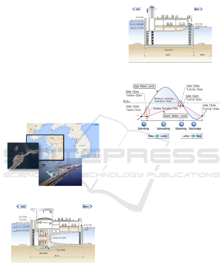
a. Structure and Components
The construction of the Sihwa Lake tidal power plant
is similar to the first case study, La Rance tidal power
plant. For size, specifications can be seen in Figures
15 and 16.
b. Turbine
Technical Data for turbines used in Sihwa lake tidal
power station is 10 bulb turbine diameter runner 7.5
m with output of 25.4 MW and output generator 26.8
MVA, Rated speed 64.3 rpm, Rated head 5.82 m,
Rated discharge 482.1 m³/s, voltage rating 10.2 kV,
current rating 1515 A, annual energy production is
around 550 GWh.
c. Working Cycle
This power plant cycle uses a 1-way generation cycle
that is a tidal generation, meaning that the flow of
water used to turn turbines is a tidal stream. With data
of basin area 56 Km2. This unit operates 2x in a day
as illustrated in Figure 17.
Figure 14: Location Sihwa tidal power plant
Figure 15: Construction of the powerhouse Sihwa tidal
Figure 16: Construction dyke Sihwa tidal power plant
Figure 17: Sihwa tidal power plant work cycle
3.3 Strangford Narrows MCT, Northen
Ireland
Seagen is the first large-scale commercial tidal power
plant in the world. The first seagen was installed at
Strangford Narrows between Strangford and
Portaferry in Northern Ireland, England in April 2008
and connected to the grid in July 2008. The turbine
generates 1.2 MW between 18 and 20 hours a day
when tides rise and exit from Strangford Lough
through a pronged cleft (Narrow) As shown in Figure
18. SeaGen S 1.2MW system is capable of generating
up to 20MWh of energy per day in Strangford, whilst
totaling 6,000MWh per year. This equals the average
energy generated from the 2.4 MW wind turbine
(MCT, 2013). The seagen turbine weighs 300t; each
turbine drives the generator through a gearbox such
as a water turbine or wind in general. This turbine has
a feature where both blades can rotate up to 180
degrees allowing them to operate in both directions -
on tidal and flood tides. The rotor can be lifted up
through the water surface to anticipate when the
current is too strong beyond the limit of the rotor's
ability. Its feature design allows the S-turbine tidal
stream turbine system to achieve 48% efficiency at
various current velocities as illustrated in Figure 19.
ICOSTEERR 2018 - International Conference of Science, Technology, Engineering, Environmental and Ramification Researches
284

Figure 18: Location of Seagen S tidal Stream Turbine
Figure 19: (a) Seagen S tidal Stream Turbine component;
(b) visualization of the turbine sweep area
4 DISCUSSION
Comparing the two types of La Rance, France and
Sihwa Korea generators, there are differences and
similarities, that is, La Rance was built approximately
45 years earlier than Sihwa, obviously the
development of technology makes it easier to build a
similar power plant with a larger capacity where La
rance capacity 240 MW with 24 turbines of 10 MW
while Sihwa power plant uses 10 turbine units with a
capacity of 25.4 MW. The diameter of the turbine
sihwa is greater that is 7.5m while La Rance 5.35m.
with half the cost of La Rance developer sihwa tidal
power can build a plant with a better capacity of €
580m or equivalent to the US $ 656.44m, while the
cost of building a tidal power plant of US $ 355.1m.
it is because the existing embankment construction at
Sihwa lake has been previously made for agricultural
purposes. Another difference is seen from the work
cycle in which the La Rance power plant works in two
directions, the generation whereas the tidal power
plant works in one direction where we know that in
some places the tidal generation is less effective as
the tidal generation because the water discharge is
likely to be out of control. For tidal stream turbine
type generation in accordance with the theory that the
greater the area of turbine sweep with the same
current velocity yields greater energy as attached in
Table 2.
Table 2: Comparison between PLTPS
No
.
Aspect of
Review
PLTPS Unit
La Rance Sihwa Strangford
1 Location France
South
Korea
Northern
Ireland
2. Year 1966 2011 2008
3
Tidal
heigh
t
8,2 m 6.3 m -
4
Tidal
current
velocity
- - 2,4 m/s
5
Conversion
system
Barrage barrage stream
6
Type of
turbine
Bulb Bulb
Horizontal
axis
7
D-runner
turbine
5.35 m 7 m 16 m
8
Number of
turbines
24 unit
@10
MW
10 unit @
25.4 MW
2 unit @
600 kW
9
Working
cycle
2 ways 1 way 2 ways
10 Capacity 240 MW 254 MW 1.2 MW
11
Annual
energy
540 GWh 552.7 GWh 6 GWh
12
Developme
nt costs
US$ 656.
44m
US$
355.1 m
€ 3.6 m
5 CONCLUSION
From the results of the discussion we obtained the
following conclusions:
1. PLTPs are subdivided according to their energy
extraction method, i.e., potential energy that is
vertical water movement associated with the ups and
downs of tidal and kinetic energy which is the result
of the horizontal motion of water which is also called
as tidal current.
2. The prospect of the implementation of the
development of marine energy utilization, especially
tidal energy is good enough to be seen from the
potential of Indonesia sea that has the range and speed
of current that meet the requirements, especially in
several straits in eastern Indonesia.
3. Location determination, selection of turbine
type, and type of duty cycle are determined by the
characteristics of the location itself either from its
topology, tidal range, and its tidal current velocity.
A Comprehensive Study of Sea Wave Tidal Power Plant (PLTPS)
285

REFERENCES
Araquistain, T.M., Tidal Power: Economic and
Technological Assessment. Department.
British Hydropower Association (BHA), 2009. La Rance
Tidal Power Plant, Liverpool.
International Energy Agency (IEA) Statistics, 2015. Key
Trends in CO
2
Emissions Excerpt from CO
2
Emissions
From Fuel Combustion.
Khaligh A;” Energy Harvesting.” Illinois Institute of
Technology 2008.
Marine Current Turbine (MCT), 2013. Seagen-S 2MW,
Proven, and Commercially Viable Tidal Energy
Generation.
Schneeberger M., 2008. Sihwa Tidal – Turbines And
Generators For The World‘s Largest Tidal Power
Plant, Andritz Va Tech Hydro, Bristol.
The royal academy of engineering, Wind Turbine Power
Calculations RWE power renewable, Mechanical, and
Electrical Engineering Power Industry.
ICOSTEERR 2018 - International Conference of Science, Technology, Engineering, Environmental and Ramification Researches
286
