
Underground Radio Signal Attenuation at 109.8 MHz
Suherman
1
, Ali Hanafiah
1
, Naemah Mubarakah
1
, and Agustiar Widodo
1
Universitas Sumatera Utara, Medan, Indonesia
Keywords: Signal Attenuation, Underground Radio Propagation, Radio through the Earth.
Abstract: Underground radio propagation measurement is an interesting work as its application very much helping on
enabling radio through the earth (TTE) application. TTE enablesunderground work to communicate with
people on surface. The ground consists of various materials rapidly degrading signal level. This paper
performs an experiment to enable frequency of 109.8 MHz to be used as radio to the earth application. The
mathematical model is used to predict the attenuation pattern. However, as model proposed by different
measurement places, an experiment by measuring directly to ground attenuation is conducted to confirm the
model precision. The measurement shows significant error up to 16.18%, which results some parameters
adjustment on the model. By adjusting the earth parameter, error is reduced to 11.17%.
1 INTRODUCTION
Radio signal passes underground experiencing
various scattering, absorption and signal dispersion
which results significant signal attenuation.Signal
attenuation is even worse when frequency is higher.
Some underground applications employsvery high
frequency (VHF) band as its attenuation is
acceptable and capacity is permissible (Vuran,
2010). In order to predict attenuation level,
mathematical model is employed. However, as
model used in different location, experiment
validation should be performed (Akyildiz, 2009).
Despite the simplicity of experiment reported by this
paper, TTE application for available 109.8 Band is
not yet reported. This work is to make sure this
frequency is suitable enough for the forthcoming
TTE design.
The famous earth attenuation model was
proposed by Friis (Fauzi and Maulana, 2017) as
described by Equation 1. The higher frequency, the
higher the loss. To obtain acceptable threshold level
in the receiver, transmitting power should be high
enough. In order to do so, loss signal should be
correctly predicted. The correction factors which
include earth dispersion, absorption and scattering
are added (Equation 2) (Akyildiz, 2007).
L(dB) = 32:4 + 20 log(d) + 20 log(f)
(1)
L(dB) = 6.4 + 20 log(d)(m) +
20log(β)+8.69 αd
(2)
The attenuation parameter is represented by α,
the shifting of signal phase is adjusted by using β.
Both parameters are varied to the type of ground as
the earth dielectric changes frequently depending the
materials. The values are approximated by Peplinski
using permittivity and permeability measured
directly fromthe ground materials (Li, 2007).
(3)
(4)
The permeability of the measured ground sample
is relatively closed to µ
0
.So the value of µ
0
is set to
one (Mietzner, 2012).
2 EXPERIMENT DESIGN
The following is the experiment design to validate
the Friss model that is used for predicting signal
attenuation on TTE working on 109.8 MHz. Signal
188
Suherman, ., Hanafiah, A., Mubarakah, N. and Widodo, A.
Underground Radio Signal Attenuation at 109.8 MHz.
DOI: 10.5220/0010074601880191
In Proceedings of the International Conference of Science, Technology, Engineering, Environmental and Ramification Researches (ICOSTEERR 2018) - Research in Industry 4.0, pages
188-191
ISBN: 978-989-758-449-7
Copyright
c
2020 by SCITEPRESS – Science and Technology Publications, Lda. All rights reserved
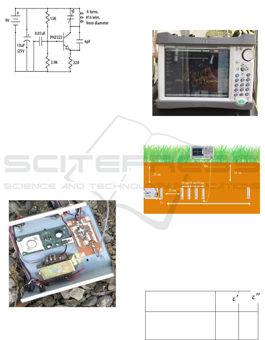
generator is devised by using a transistor performing
an oscillating circuit as illustrated in Figure 1
(Mietzner, 2012).
Figure 1. 109.8 MHzoscillator
The LC circuit tank consisting of C1 and L1 are
combined to genera tesignal on 109.8MHz.By
switching on the transistor Q1, the multifrequency
signals is generated. The tuned circuit LC adjusts
which frequency is feedbacked to the basis of the
transistor.
This signal is repeatedly amplified until stability
is obtained. The desired frequency has enough
amplitude level to be radiated by a wire antenna that
is connected inbetween inductor and capacitor.
To activate the signal generator, a two-diodes
adaptor circuit is assembled as shown in Figure 2.
To enable increasing transmitting power level,
output voltagesare set to be adjustable from 6 volt to
9 Volt.
Figure 2. Transmitter and power supply modules
In order to analysis the received power, a vector
network analyser that work as frequency spectrum
analyser is used (Figure 3). A monopole wire
antenna with length of 1/8 λ isconnected each to
transmitter and to network analyser.
The total antennalength of 27.317 cm made by
wire is devised as the system antennas. The
measurement point is set as shown in Figure 4.
Figure 3. Network analyser
Figure 4. Measurement plan
The ground material samplesare rocky with small
stones mixed with the dirty ground. The location of
monitoring is in Electrical Engineering Building
within Universitas Sumatera Utara.
For the analysis purpose, the dielectric
parameters are approximated by employing those in
Table 1 (Sadeghioon et al., 2017).
Table 1. Dielectric parameters
Type
Ground with mud and
stone
6.53
1.88
Underground Radio Signal Attenuation at 109.8 MHz
189
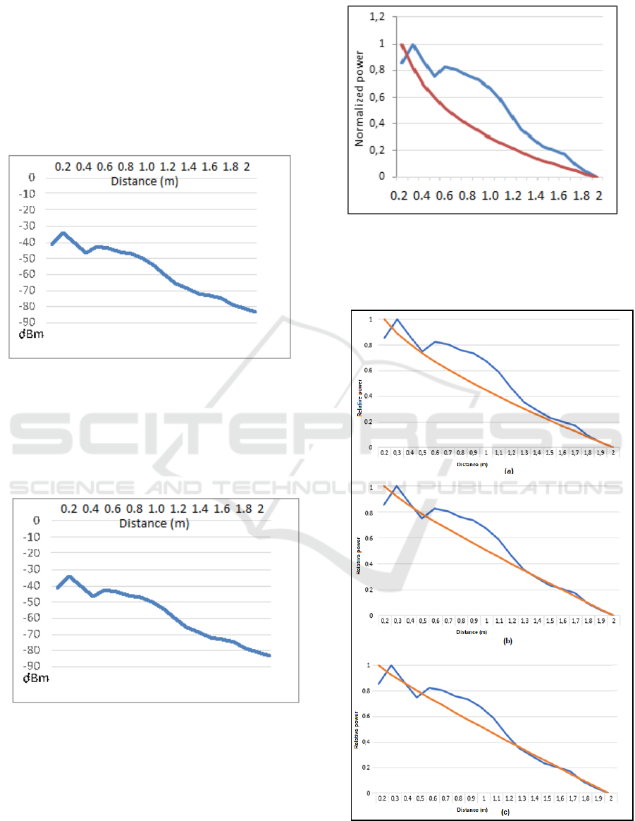
3 RESULTS
The results of attenuation measurement in dBm are
depicted in Figure 5. The signal received by the
VNA degrades as distance increases. Signal
decreases from about -35 dBm at 20 cm to -80 dBm
at 2 m This means that signal attenuation is about
20dBm/m.
Figure 5. Measurement data
By applying Friss mode using the
aforementioned equations and the ground parameters
of α = 0,000503548 and β = 0,002038259, the
attenuation is plotted as in Figure 6.
Figure 6. Mathematical analysis
Both results show the same pattern, decreasing
signals to increasing distance. The values are then
compared as shown in Figure 7. The average error
obtained from the experiment and the model is quite
high, 16.18%. This pattern error is primarily caused
by the error on the earth parameters.
Figure 7. Pattern comparisons
By adjusting the parameters of ground dielectric
from 20 (Figure 8a), 30 (Figure 8b) and 50 (Figure
8c), error can be minimized up to 11.17%.
Figure 8. Adjustment results
ICOSTEERR 2018 - International Conference of Science, Technology, Engineering, Environmental and Ramification Researches
190

4 CONCLUSIONS
This articleexamined signal attenuation by the earth
by means of measurement and mathematical model.
Signal attenuates as distance increases. In average,
signal degradation is about 20dB/m. After evaluating
the model by using direct measurement, the error of
both model and measurement is 16.18% in average.
Error can be decreased up to 11.17% by adjusting
the ground dielectric parameter, which is the most
important thing to get the precise model.
ACKNOWLEDGEMENT
This research has been supported by DRPM DIKTI
under the Penelitian Dasar Unggulan Perguruan
Tinggi research grant 2018.
REFERENCES
Akyildiz, I. F., Sun, Z., & Vuran, M. C. (2009) ‘Signal
propagation techniques for wireless underground
communication networks’, Physical Communication,
2(3), p. 167–183.
Fauzi, R., & Maulana, R. (2017) ‘Designing and
Characterizing Periodic Image Monitoring Device for
Remote Surveillance Purpose’, Journal of Physics:
Conference Series. IOP Publishing, 801(1), p. 012082.
Li, L., Vuran, M. C., & Akyildiz, I. F. (2007)
‘Characteristics of underground channel for wireless
underground sensor networks’, in In Proc. Med-Hoc-
Net, p. Vol. 7, pp. 13–15.
Mietzner, J., Nickel, P., Meusling, A., Loos, P., & Bauch,
G. (2012) ‘Responsive communications jamming
against radio-controlled improvised explosive
devices’, IEEE Communications magazine,XXX,
50(10), p. 38–46.
Sadeghioon, A. M., Chapman, D. N., Metje, N., &
Anthony, C. J. (2017) ‘A New Approach to Estimating
the Path Loss in Underground Wireless Sensor
Networks’, Journal of Sensor and Actuator Networks,
6(3), p. 18.
Takahashi, K., Igel, J., Preetz, H., & Kuroda, S. (2012)
‘Basics and application of ground-penetrating radar as
a tool for monitoring irrigation process’, Problems,
perspectives and challenges of agricultural water
management.
Vuran, M. C., & Akyildiz, I. F. (2010) ‘Channel model
and analysis for wireless underground sensor networks
in soil medium’, Physical Communication, 3(4), p.
245–254.
Underground Radio Signal Attenuation at 109.8 MHz
191
